coms manual.qxp
coms manual.qxp
coms manual.qxp
- No tags were found...

You also want an ePaper? Increase the reach of your titles
YUMPU automatically turns print PDFs into web optimized ePapers that Google loves.
OPTIMASSCommunications Handbook for the MFC 300Communication options for:• MFC 300 PROFIBUS DP (RS485 device with PA profile)• MFC 300 PROFIBUS PA (MBP device with PA profile)
CONTENTSOPTIMASS1. Introduction1.1 General . . . . . . . . . . . . . . . . . . . . . . . . . . . . . . . . . . . . . . . . . . . . . . . . . . . . . . . . . . . . . . . . . .61.2 Items included with supply . . . . . . . . . . . . . . . . . . . . . . . . . . . . . . . . . . . . . . . . . . . . . . . . .61.3 Special Notes . . . . . . . . . . . . . . . . . . . . . . . . . . . . . . . . . . . . . . . . . . . . . . . . . . . . . . . . . . . . .62. PROFIBUS DP Device With RS-485 Interface2.1 Software History . . . . . . . . . . . . . . . . . . . . . . . . . . . . . . . . . . . . . . . . . . . . . . . . . . . . . . . . . .72.2 PRIOFIBUS DP System Architecure . . . . . . . . . . . . . . . . . . . . . . . . . . . . . . . . . . . . . . . . . . .72.3 Bus Conection PROFIBUS DP Device . . . . . . . . . . . . . . . . . . . . . . . . . . . . . . . . . . . . . . . . . .72.4 GSD Files . . . . . . . . . . . . . . . . . . . . . . . . . . . . . . . . . . . . . . . . . . . . . . . . . . . . . . . . . . . . . . . . .92.4.1 Manufacturer specific GSD file: KR014510.GSD . . . . . . . . . . . . . . . . . . . . . . . . . .92.4.2 Profile specific GSD file: PA039742. GSD . . . . . . . . . . . . . . . . . . . . . . . . . . . . . . .112.4.3 Cyclic data exchange . . . . . . . . . . . . . . . . . . . . . . . . . . . . . . . . . . . . . . . . . . . . . . . .112.5 Profile . . . . . . . . . . . . . . . . . . . . . . . . . . . . . . . . . . . . . . . . . . . . . . . . . . . . . . . . . . . . . . . . . . .122.6 Data Structure of Function Block Output Values . . . . . . . . . . . . . . . . . . . . . . . . . . . . . . . .122.7. Diagnosis . . . . . . . . . . . . . . . . . . . . . . . . . . . . . . . . . . . . . . . . . . . . . . . . . . . . . . . . . . . . . . . .132.8 Display Parameters (PROFIBUS) . . . . . . . . . . . . . . . . . . . . . . . . . . . . . . . . . . . . . . . . . . . . .142.9 Technical Data . . . . . . . . . . . . . . . . . . . . . . . . . . . . . . . . . . . . . . . . . . . . . . . . . . . . . . . . . . . .213. PROFIBUS PA DEVICE (MBP INTERFACE & PA PROFILE 3.01)3.1 Software History . . . . . . . . . . . . . . . . . . . . . . . . . . . . . . . . . . . . . . . . . . . . . . . . . . . . . . . . . .223.2 PROFIBUS PA System Architecture . . . . . . . . . . . . . . . . . . . . . . . . . . . . . . . . . . . . . . . . . . .223.3 Bus Connection - PROFIBUS PA Device . . . . . . . . . . . . . . . . . . . . . . . . . . . . . . . . . . . . . . .233.4 GSD Files . . . . . . . . . . . . . . . . . . . . . . . . . . . . . . . . . . . . . . . . . . . . . . . . . . . . . . . . . . . . . . . . .243.4.1 Manufacturer specific GSD file: KRO14511.GSD & YPO124511.GSD . . . . . . . . .243.4.2 Profile specific GSD file: PA2139742. GSD . . . . . . . . . . . . . . . . . . . . . . . . . . . . . .263.4.3 Cyclic data exchange . . . . . . . . . . . . . . . . . . . . . . . . . . . . . . . . . . . . . . . . . . . . . . . .263.5 Profile . . . . . . . . . . . . . . . . . . . . . . . . . . . . . . . . . . . . . . . . . . . . . . . . . . . . . . . . . . . . . . . . . . .273.6 Data Structure of Function Block Output Values . . . . . . . . . . . . . . . . . . . . . . . . . . . . . . . .273.7 Diagnosis . . . . . . . . . . . . . . . . . . . . . . . . . . . . . . . . . . . . . . . . . . . . . . . . . . . . . . . . . . . . . . . . .283.8. Display Parameters (PROFIBUS) . . . . . . . . . . . . . . . . . . . . . . . . . . . . . . . . . . . . . . . . . . . .293.9 Technical Data . . . . . . . . . . . . . . . . . . . . . . . . . . . . . . . . . . . . . . . . . . . . . . . . . . . . . . . . . . . .373
Explanation of Symbols UsedThe follwing is a guide to the meaning of the symbols used in this handbook.The symbols fallinto two types. The rectangular symbols with blue background draws the reader’s attention togeneral points of information. The triangular symbols with yellow background draw the reader’sattention to hazards or hazardous situations.General InformationInformation is important to theinstallation/operation of the meter.General WarningRisk of damage to the meter or installation.EX - Hazardous Area WarningInstruction MUST be observed in order tocomply with Hazardous Areas Certification.High VoltageRisk of electric shock.General HazardNon specific hazard that could result in injury.Hot Surface or High TemperatureRisk of burning.Heavy ItemRisk of injury.• Do not install, operate or maintain this device without reading, understanding and followingthe factory-supplied handbook. Failure to do so, may result in injury or damage.• Read these instructions carefully before starting installation and save them for future reference.• Observe all warnings and instructions marked on the device.• You MUST only use a power supply that has a protective earth.• Do not use the device with covers removed!• You MUST follow the installation instructions in the handbook, paying particular attentionto• Handling• Lifting• Supporting and fixing the meter• Cabling and connections.• If the product does not operate normally, refer to the handbook or consult a qualifiedKROHNE service engineer. There are no operator-serviceable parts inside the product.4
These terms may appear in this <strong>manual</strong> or on the instrument:Warning statement: Identify conditions or practice that could result in injury or loss of life.orCaution statement: Identify conditions or practice that could result in damage to the instrumentor other property.Disclaimer:• This document contains important information on the device. KROHNE attempts to be asaccurate and up-to-date as possible but assumes no responsibility for errors or omissions.Nor does KROHNE make any commitment to update the information contained herein. This<strong>manual</strong> and all other documents are subject to change without prior notice.• KROHNE will not be liable for any damage of any kind by using this device, including, butnot limited to: direct; indirect; incidental; punitive and consequential damages.• Any device purchased from KROHNE is warranted in accordance with the relevant productdocumentation and our Terms and Conditions of Sale.• KROHNE reserves the right to alter the content of its documents, including this disclaimerin any way, at any time, for any reason, without prior notification and will not be liable in anyway for possible consequences of such changes.Product liability and Warranty• Responsibility for suitability and intended use of this device rests solely with the user.Improper installation and operation of the device may lead to loss of warranty.• In addition, the Terms and Conditions of Sale are applicable and are the basis for the purchasecontract.• If a device needs to be returned to KROHNE, please note the information given at the backof the Handbook. KROHNE regrets that they cannot repair or service a device unlessaccompanied by the completed formThis instrument has been developed and manufactured by:KROHNE LtdRutherford DrivePark Farm Industrial EstateWellingboroughNorthantsNN8 6AEUnited KingdomFor information, maintenance or service, please contact your nearest local KROHNE representative.See www.krohne.comWARNINGNo changes may be made to the devices. Unauthorized changes might affect the explosionsafety of the devices. Be sure to follow these instructions!IMPORTANT• The prescriptions, regulations and electrical data described in the EC type examination certificateMUST be obeyed.• In addition to the general regulations for low-voltage installations (e.g.HD384) the regulationslaid down in the standard for electrical installations in gas hazardous areas (e.g. EN60079-14) or dust hazardous areas (e.g. EN 50 281-1-2) MUST be complied with.• Installation, commissioning, utilization and maintenance must be carried out only by personneltrained in explosion safety.• This <strong>manual</strong> must be read in conjunction with the OPTIMASS / OPTIGAS Handbooks.5
1 INTRODUCTIONOPTIMASS1.1 GeneralThese Instructions are supplementary to the “MFC300 (OPTIMASS) Handbook”. You must followthat handbook in particular the Safety Information These Supplementary Instructions provideadditional information for device operation and connection to a PROFIBUS fieldbus.1.2 Items included with supplyIn addition to the standard scope of supply, these Supplementary Instructions for the MFC300PROFIBUS RS-485 Interface will be included.1.3 Special Notes• Don’t switch off (power off) the MFC300 immediately after <strong>manual</strong> change of parameter values:• Please wait approx. 10 seconds before you switch off the MFC300 after you have doneboth a parameter download via PROFIBUS or a <strong>manual</strong> change of a parameter valuevia the local display.• Please wait approx. 15 sec before you switch off the MFC300 after you have carriedout a “Factory Reset” (PROFIBUS “Coldstart”) via PROFIBUS or local display.• “Deactivation of the Service Parameter Lock” of the MFC300 via PROFIBUS:• After writing down the service password (via PROFIBUS) the “Deactivation of theService Parameter Lock” will last at least 10 min. if the internal password timer ofthe MFC300 won't be retriggered by writing this password again. The “Deactivation ofthe Service Parameter Lock” will be terminated at once by a PROFIBUS Cold-/Warm-Start or if the internal password timer of the MFC300 elapsed.6
2 PROFIBUS DP DEVICE WITH RS-485 INTERFACE & PA PROFILE 3.012.1 Software historyOPTIMASSIssued Signal Converter Application Program System IntegrationMonth/Year11/06Hardware Firmware Hardware Software Driver VersionMFC300 SignalConverter withRS485 Interfaceand PA Profile3.01 ("ProfibusDP device")V2.2.1/ 061117• Simatic PCS7• Others• HW Config• othersGSD(Manufacturer specific,for standardDP/PA segment coupler)GSD(Profile specific, forstandard DP/PA segmentcoupler)KR014510.GSDPA039742.GSDLaptop/ PC PDM > 6.0 DD 4510 0300 01Model Name asused in the GSD:"MFC300 (RS-485)Rev. 1""Flow,dens,temp3AI, 1TOT (PhyL 0)"Laptop/ PCPactwareDTM(generic Flow DTM)0300_1030001_FDT12.exe2.2 System ArchitecturePLCPLCPROFIBUS-DPwith max. 12 Mbit/sOther devices withPROFIBUS RS485interfaceOther devices withPROFIBUS RS485interfaceThe illustration above shows a typical instrumentation with PROFIBUS devices with RS-485interface in non-hazardous locations. The PROFIBUS devices with RS-485 interface do notneed any segment coupler. They can be connected directly to the PROFIBUS DP Network.2.3 Bus Connection Profibus DP DeviceFor a detailed description of the electrical connections of the MFC300 please refer to the OPTI-MASS Handbok.1+5VR1R2R1IIIIB B- C C- DD-I = 110nHR1 = 390R2 = 2207
2.4 GSD FilesSupported baud rates are listed in the GSD file (see below). After power-on or PROFIBUS timeouta baud rate search is active to detect the current transfer speed on the bus. It is not necessaryto set the baud rate <strong>manual</strong>ly.If the transfer speed is changed during operation the baud rate search will not be started bythe device. A new power-up or a <strong>manual</strong> interruption of the PROFIBUS communication isrequired to activate the baud rate search in this case.A “PROFIBUS GSD ZIP” file (e.g. GSD-31777815.zip) including both all KROHNE GSD files andadditional data files can be downloaded from the KROHNE homepage http://www.krohne.comor contact “KROHNE Marketing”. The GSD file contains information that will be needed forproject planning of the PROFIBUS DP communication network. The relevant data files (e.g.MFC300_n.bmp; MFC300_n.dib) must be loaded into the bus configuration system/master systembefore start-up of the bus system.The MFC300 PROFIBUS RS-485 Interface is according to the PROFIBUS PA Profile V 3.01. Thedevice supports two Ident-No:• Ident-No. “4510hex” belongs to the GSD file KR014510.GSD and includes the complete functionalityconcerning the cyclic data exchange of the coriolis mass flow meter MFC300.• The application of the manufacturer independent Ident-No. “9742hex” (GSD file“PA039742.GSD”) provides interchangeability of devices, i.e. an exchange of coriolis massflow meters of different vendors.Please follow the instructions in the <strong>manual</strong> of the host supplier when installing the GSD Fileyou need and the additional files (MFC300_n.bmp and MFC300_n.dib) into the PLC. If separatedby the bus configuration system the device entry of the MFC300 PROFIBUS RS-485 Interfacewith PA Profile 3.01 will be located within the slave family PROFIBUS PA.2.4.1 Manufacturer specific GSD file: KR014510.GSDKROHNE delivers the GSD files with the entire device functionality, as follows:BlockNumberStandard-Configurationfunction block output: value + status)KR014510.GSDIdent-No. 4510Default unit:1 Mass Flow AI-FB kg/s2 Density AI-FB kg/m33 Medium Temperature AI-FB K4 Mass Totaliser Totaliser-FB kg5 Volume Totaliser Totaliser-FB m36 Mass Totaliser Totaliser-FB kg7 Volume Flow AI-FB m3/h8 Concentration 1 AI-FB %9 Concentration 2 AI-FB %10 Concentration Mass Flow 1 AI-FB kg/s11 Concentration Mass Flow 2 AI-FB kg/s9
AI = Analog Input Function BlockFB = Function BlockThere are separate settings to select the units for local display and PROFIBUS. Modifications ofthe units of the display will have no effect on the data transferred via PROFIBUS. A masterclass 2 tool is required to modify the units for PROFIBUS transfer.During network configuration the user has to define which function block outputs of theMFC300-DP should be transferred cyclically to the master. This is done by a bus configurationtool (e.g. for PC-S7 from Siemens this will be done with the tool “HW- Config”). This tool offersthe functions described as follows:1. It is possible to configure an “Empty” block (the code of an “Empty” block is defined as0x00) on each block number. This means, that for this block no data is transmitted in thecyclic data telegram.2. There is NO “Totaliser (TOT)” function block allowed on block position 1, 2, 3, 7, 8, 9, 10 and11! An “Analog Input (AI)” function block or an “Empty” block is allowed here only!Note: All codes supported of “Analog Input (AI)” - and “Totaliser (TOT)” – function blocks willbe found in the corresponding GSD files.3. There is NO “Analog Input (AI)” function block allowed on block position 4, 5 and 6! A“Totaliser (TOT)” function block or an “Empty” block is allowed here only!4. There is a choice of 7 different totaliser functions, which can be allocated to the blocks 4, 5and / or 6. The 7 functions are defined as follows:“Total”“SetTot + Total”“ModeTot + Total”“SetTot+ModeTot+Total”“SetTot”“ModeTot”“SetTot + ModeTot”cyclic transfer of the totaliser value with status to the mastercyclic transfer of the totaliser value with status to the master + cycliccontrol data from master to the device via the parameter SetTotcyclic transfer of the totaliser value with status to the master + cycliccontrol data from master to the device via the parameter ModeTotcyclic transfer of the totaliser value with status to the master + cycliccontrol data from master to the device via the parameters SetTot andModeTot (in the given order)cyclic control data from master to the device via the parameter SetTotcyclic control data from master to the device via the parameter ModeTotcyclic control data from master to the device via the parameters SetTotand ModeTot (in the given order)The Byte SetTot and ModeTot are being sent cyclically from the Master to the device if thesebytes are inserted as output data via the PLC configurator. The meaning of these control bytesare as follows:10
SetTot:SetTot =0:SetTot =1:SetTot =2:SetTot ? 2:Totaliser is totalising.Totaliser will be reset to 0 and stays at 0 until SetTot is switched back againto 0. If the value of SetTot changes from “1” to “0” the totaliser starts countingfrom 0.Totaliser is set to the value defined by PresetTot. PresetTot can be written viaa acyclic master (totaliser in block 4 = Slot 4 Index 32; totaliser in block 5 =Slot 5 Index 32; totaliser in block 6 = Slot 6 Index 32). If the value of SetTotchanges from “2” to “0” the totaliser starts counting from the current valuedefined by PresetTot.not allowed. Value is ignored; totaliser remains in its last valid setting.ModeTot:ModeTot = 0ModeTot = 1ModeTot = 2ModeTot = 3All other values of ModeTot are not allowed. Value is ignored; totaliser remains in its last validsetting.The standard block configuration may be changed by the customer but using the default settingsis highly recommended. If the standard block configuration should be changed by thecustomer an acyclic master tool must be used to change the “channel parameter” value of theblock which should be connected to another transducer output value.2.4.2 Profile specific GSD file: PA039742. GSDThe functionality of the profile specific GSD file is limited. This GSD file includes only fourblocks:Block Numbertotaliser totalises positive and negative values.totalises only positive values.totalises only negative values.totaliser is stopped, no totalization will be done.ModeTot = 248 totalises all values as positive (negative values will be multiplied with “-1.0”)ModeTot = 249 totalises all values as negative (positive values will be multiplied with “-1.0”)Standard-Configuration(function block output value)PA039742. GSDIdent-No. 9742Defaultunit:1 Mass Flow AI-FB kg/s2 Density AI-FB kg/m33 Medium Temperature AI-FB K4 Mass Totaliser Totaliser-FB kgThe device has to be switched from “Manufacturer Specific” (full functionality) to “ProfileSpecific” (interchangeable basic configuration) by using a master class 2 tool (IDENT_NUM-BER_SELECTOR: Slot 0, Index 40 change byte value to 0). After this the device has to be projectedby using the PA039742.GSD file.2.4.3 Cyclic data exchangeDuring network configuration the user has to define which function block outputs of theMFC300 PROFIBUS RS-485 should be transferred cyclically to the master. Network configurationwill be done using one of the GSD files described above. The order of transmission of afunction block always remains the same even if a function block is defined as an “Empty” block(in this case, no function block output data will be sent to the master and all function block outputsfollowing the “Empty” block will move up one position).11
2.5 ProfilesThe MFC300 PROFIBUS RS-485 Interface supports the PROFIBUS PA Profile Version 3.01.The MFC300 PROFIBUS RS-485 Interface with PA Profile 3.01 supports the following blocks:• One physical block.This block contains the parameters defined in PA Profile 3.01.• One transducer block for coriolis mass flow devices.This block provides the parameters and functions defined in PA Profile 3.01.• Eight “Analog Input (AI)” function blocks: as default “Mass Flow”, “Density”, “MediumTemperature”, “Volume Flow”, “Concentration 1”, “Concentration 2”, “Concentration MassFlow 1” and “Concentration Mass Flow 2”.• Three “Totaliser (TOT)” function blocks: as default the first and the third totaliser willtotalise “Mass” and second one will totalise “Volume”2.6 Data Structure of Function Block Output ValuesThe data structure of function block outputs consists of 5 bytes: a 4 byte float value (FloatFormat according IEEE Standard 754 Short Real Number) followed by a 1 byte status value. Ifall 11 function block outputs have been projected (see above), 55 byte will be transmitted.Float ValueThe following table gives an example of the float formatByte n Byte n+1 Byte n+2 Byte n+3Bit7 Bit6 Bit7 Bit6 Bit7 Bit7VZ 2 7 2 6 2 5 2 4 2 3 2 2 2 1 2 0 2 -1 2 -2 2 -3 2 -4 2 -5 2 -6 2 -7 2 -8 2 -9 2 -10 2 -11 2 -12 2 -13 2 -14 2 -15 2 -16 2 -17 2 -18 2 -19 2 -20 2 -21 2 -22 2 -23Exponent Mantissa Mantissa MantissaExample:40 F0 00 00 (hex) = 0100 0000 1111 0000 0000 0000 0000 0000 (binary)Formula: Value = (-1)VZ * 2 (Exponent - 127) * (1 + Mantissa)Value = (-1)0 * 2 (129 - 127) * (1 + 2 -1 + 2 -2 + 2 -3 )Value = 1 * 4 * (1 + 0,5 + 0,25 + 0,125)Value = 7,5Status ValueThe meanings of the status byte (unsigned integer) are given in the following tablesQuality Quality-Substatus LimitsGr Gr QS QS QS QS Qu Qu2 7 2 6 2 5 2 4 2 3 2 2 2 1 2 00 0 = bad0 1 = uncertain1 0 = good (Non Cascade)1 1 = good (Cascade) - not supported12Status = bad0 0 0 0 0 0 = non-specific0 0 0 0 0 1 = configuration error0 0 0 0 1 0 = not connected0 0 0 0 1 1 = device failure0 0 0 1 0 0 = sensor failure0 0 0 1 0 1 = no communication (last usable value)0 0 0 1 1 0 = no communication (no usable value)0 0 0 1 1 1 = out of service
Status = uncertain0 1 0 0 0 0 = non-specific0 1 0 0 0 1 = last usable value0 1 0 0 1 0 = substitute-set0 1 0 0 1 1 = initial value0 1 0 1 0 0 = sensor conversion not accurate0 1 0 1 0 1 = engineering unit violation (unit not in the valid set)0 1 0 1 1 0 = sub-normal0 1 0 1 1 1 = configuration error0 1 1 0 0 0 = simulated value0 1 1 0 0 1 = sensor calibrationStatus = good (Non-Cascade)1 0 0 0 0 0 = ok1 0 0 0 0 1 = update event1 0 0 0 1 0 = active advisory alarm (priority < 8)1 0 0 0 1 1 = active critical alarm (priority > 8)1 0 0 1 0 0 = unacknowledged update event1 0 0 1 0 1 = unacknowledged advisory alarm1 0 0 1 1 0 = unacknowledged critical alarm1 0 1 0 0 0 = initiate fail safe1 0 1 0 0 1 = maintenance requiredStatus = Limits0 0 = ok0 1 = low limited1 0 = high limited1 1 = constantCheck the first two quality bits in order to get the quality information of the measurementvalue:Good(non Cascade)Good(Cascade)Uncertainfunction block output value is ok and can be used without restrictionswill not be supported, because it is not applicable for the devicefunction block output value can be used but the accuracy can not be guaranteed(e.g. function block outputs value has been frozen or A/D converteris saturated or out of range)Badfunction block output value is bad - don’t use it for process control!The „Quality-Substatus“- and „Limit“-Bits will be used for further diagnostics or limit checking.Attention: The status should be monitored because a number will be transmitted even ifthe status of the measurement value is bad or uncertain. This is the only way to check thequality of the transmitted measurement values.2.7 DiagnosisIf the device internal diagnostic functions detect an error additional information will be sent tothe Master (for further information have a look at the UNIT_DIAG_BIT(i) definitions of the correspondingGSD-file).13
2.8 Display Paramters (PROFIBUS)(MFC300 PROFIBUS RS-485 Interface with PA Profile 3.01)For a detailed description please see ”MFC 300 (OPTIMASS) Handbook”. Some special settings concerningthe PROFIBUS features easily operated via the local menu are described in the following tables.A Quick SetupRef Display Description & SettingsA3A4ResetStation AddressThis menu function can be used to reset allerrors that are not removed automatically(power fail, counter overflow)A3.1 Reset Errorsstep 1: reset?No: Exit the functionYes Resets the errors and exits the function.The following reset menus for the counters (totaliser) are only available, ifthe quick access has been activated in the menu setup > device > quicksetup. Each counter (totaliser) can be activated for quick access independently.A3.2 > FB4 Totaliser 1A3.3 > FB5 Totaliser 2A3.4 > FB6 Totaliser 3(where fitted)(for PROFIBUS Devices) the counter can bereset to zero in this menustep 1: reset counter?no: exits the function without resetyes: resets the counter and exits the functionfor PROFIBUS Devices the counter can bereset to zero in this menustep 1: reset counter?No exits the function without resetYes resets the counter and exits the function(for PROFIBUS Devices) the counter can bereset to zero in this menustep 1: reset counter?No exits the function without resetYes resets the counter and exits the function(only for PROFIBUS devices)A4 -> Station Address selects the address of the device at the PROFIBUSDP interface.Note:The PROFIBUS address can also be changed using the PROFIBUS service“set_slave_add”. The input range is 0...125 according to the PROFIBUS specification.Address 126 is the default address and cannot be set via thePROFIBUS service “set_slave_add” - use menu instead to reset to defaultaddress.B Test levelB3 InformationB3.5 PROFIBUSavailable if there is a PROFIBUS interface in existence; displays thebelow mentioned information about the PROFIBUS interface:KROHNE Ident No.Software Revision of the PROFIBUS softwareDate of Production14
C SetupC4 I/O TotaliserC 4.y Totaliser 1, 2 or 3Allows you to control the three PROFIBUS counters The three menusare identical so they are grouped together and their functions aredescribed in one go.C 4.y.1 Function of Totaliser Incremental Total Totalises only positive valuesDecremental TotalAbsolute TotalStop TotaliserAll As PositiveAll As NegativeTotalises only negative valuesTotalises positive and negative valuesTotaliser is stopped.neg. input values will be multiplied with"-1.0"pos. input values will be multiplied with"-1.0"C 4.y.2C 4.y.3C 4.y.4C 4.y.5MeasurementPreset ValueReset TotaliserError behaviour• Volume flow • Mass flow• Voncentration total1 • Concentration total2• Conc volume flow 1 • Conc volume flow 2(predefines a “threshold” using the High Limit value and the Low Limitvalue of the totaliser affected; the “THRESHOLD” bit will be set in thelong status information bytes of the PROFIBUS interface if the actualvalue of the totaliser is outside these limits. This can be also used as astatus output choosing the function "preset counter X”(The current value of the totaliser can be set to zero)Step 1: reset totaliser?no: exits the function without resetyes: resets the totaliser to zero and exits the function; totaliserwill restart counting at once(defines the behaviour of this function block in case of errors)totalization is continued based on thelast incoming value with good statushold meas. valuebefore the first occurrence of bad statusignore error:totalization is continued using the inputvalues despite the bad status. The statusis ignoredstop totalisertotalization is stopped during occurrenceof bad status of incoming valuesC 4.y.6information(The KROHNE Ident. No. of the circuit board, the software versionnumber and the production date of the circuit board will be displayed)Note:If you choose “y” = 1 all settings will effect FB 4 (Totaliser 1)if you choose “y” = 2 all settings will effect FB 5 (Totaliser 2)if you choose “y” = 3 all settings will effect FB 6 (Totaliser 3)15
Ref Display Description & SettingsC5 I/O PROFIBUS (This feature is available for PROFIBUS devices only.)Using the menu functions mentioned below you will be able to control basically the eight analogue inputblocks of this PROFIBUS device. These eight menus are identical so they are grouped together and theirfunctions are described in one go.C5.y.1MeasurementSelects the measurement (channel) for the analogue input block forthe PROFIBUS interfaceMass flow:TemperatureDensity: Concentration 1:Concentration 2: Concentration mass flow 2Concentration mass flow 1: Concentration volume flow 1Concentration volume flow 2 Sensor deviation:Sensor average:Drive energyTube frequency:Tube strainInner cylinder strain: Electronics temperature *Flow velocityVolume flowSupply*** This is the electronic temperature** This is internal supply voltage for the PROFIBUSC5.y.2 Time Constant Time constant for this function blockDefines the behaviour of this function block in case of errorsC5.y.3Error BehaviourHold Value:Ignore Error:last valid OUT value stored will be used asOUT valueOUT has the wrong calculated value and statusBad as calculatedReplace Value:“replacement value” will be used as OUT valueNote:If you choose “y” = 1 all settings will effect FB 1 (Analog Inp.1)if you choose “y” = 2 all settings will effect FB 2 (Analog Inp.2)if you choose “y” = 3 all settings will effect FB 3 (Analog Inp.3)if you choose “y” = 4 all settings will effect FB 7 (Analog Inp.4)if you choose “y” = 5 all settings will effect FB 8 (Analog Inp.5)if you choose “y” = 6 all settings will effect FB 9 (Analog Inp.6)if you choose “y” = 7 all settings will effect FB 10 (Analog Inp.7)if you choose “y” = 8 all settings will effect FB 11 (Analog Inp.8)C6 -> DeviceIn this menu all functions are grouped that have no effect on the measurement or any output directly.One lineDisplay shows one line of measurement onthis pageC6.3.1FunctionTwo linesDisplay shows two lines of measurement onthis pageThree linesDisplay shows three lines of measurement onthis page16
Ref Display Description & SettingsC6 Device ctd...C6.3.2C6.3.8C6.3.10C6.4 -> 2. Meas. pageMeasurement 1.lineMeasurement 2.line(Only available if thisline is activated)Measurement 3.line(Only available if thisline is activated)Mass flow:TemperatureDensity: Concentration 1Concentration flow 1 Diagnosis 1Diagnosis 2: Diagnosis 3Flow Velocity:VolumeFlowBargraph*Flow VelocityVolume Flow:Mass FlowTemperature:DensityConcentration 1: Concentration Flow 1Diagnosis 1: Diagnosis 2Diagnosis 3: FB4 Totaliser 1FB5 totaliser 2: FB6 Totaliser 3Operating Hours* Analogue display of the value selected for the first lineFlow VelocityVolume Flow:Mass FlowTemperature:Density Concentration 1:Concentration Flow 1 Diagnosis 1:Diagnosis 2 Diagnosis 3:FB4 Totaliser 1 FB5 totaliser 2:FB6 Totaliser 3Operating HoursIn case of a PROFIBUS device the second measurement page is meant to check the output values of thedifferent function blocks. Only PROFIBUS values can be selected here. The analogue inputs are shown withexactly the value, as seen on the PROFIBUS.C6.4.1C6.4.2C6.4.3C6.4.4C6.4.5Measurement 1.lineFormat 1.lineMeasurement 2.lineFormat 2.lineMeasurement 3.lineFB1 Analog inp. 1 FB2 Analog inp. 2FB3 Analog inp. 3 FB4 Totaliser 1FB5 Totaliser 2 FB6 Totaliser 3FB7 Analog inp. 4: FB8 Analog inp. 5FB9 Analog inp. 6: FB10 Analog inp. 7FB11 Analog inp. 8Fixed number of digits after the decimal point or automatic, wherethe number of digits is automatically adjusted to the available space.FB1 Analog inp. 1 FB2 Analog inp. 2FB3 Analog inp. 3 FB4 Totaliser 1FB5 Totaliser 2 FB6 Totaliser 3FB7 Analog inp. 4: FB8 Analog inp. 5FB9 Analog inp. 6: FB10 Analog inp. 7FB11 Analog inp. 8Fixed number of digits after the decimal point or automatic, wherethe number of digits is automatically adjusted to the available space.FB1 Analog inp. 1 FB2 Analog inp. 2FB3 Analog inp. 3 FB4 Totaliser 1FB5 TOTALISER 2 FB6 Totaliser 3FB7 Analog inp. 4: FB8 Analog inp. 5FB9 Analog inp. 6: FB10 Analog inp. 7FB11 Analog inp. 8C6.4.6Format 3.lineFixed number of digits after the decimal point or automatic, wherethe number of digits is automatically adjusted to the available space.17
Ref Display Description & SettingsC6 Device ctd...C6.6 Special FunctionsC6.6.1Reset ErrorsThis menu function can be used to reset all errors, that are notremoved automatically (e.g. power fail)step 1:Reset?no: exit the functionyes: resets the errors and exits the function.In this menu all settings can be saved in different storage places)Save Settings?breakExit the menu without savingStep 1backup 1Saves the settings in the backup 1 storageplaceC6.6.2Save Settingsbackup 2Saves the settings in the backup 2 storageplaceGo on with copy? (Note: There is no possibility toundo this command!)Step 2NoYesExit function without savingCopy the actual settings to the selected storageplace and exits the function.Note: PROFIBUS interface settings will not be saved(in this menu all settings can be loaded from different storage places,where settings have been saved before)Load Settings?breakExits the menu without loadingC6.6.3Load Settingsstep 1factory settingsbackup 1backup 2Loads the settings from the deliveryLoads the settings from the backup1 storage place)Loads the settings from the backup2 storage place)step 2go on with copy? (Note: There is no possibility toundo this command!)Noexit function without savingYes copy the actual settings to the selected storageplace and exits the functionNote: PROFIBUS interface settings will not be loadedC6.8 Physical Block This menu is only available, if a PROFIBUS interface is presentSelects the PROFIBUS station address of the deviceC6.8.1Station AddressNote:The PROFIBUS address can also be changed using the PROFIBUSservice “set_slave_add”. The input range is 0...125 according to thePROFIBUS specification. Address 126 is the default address and cannotbe set via the PROFIBUS service “set_slave_add” - use menuinstead to reset to default address.18
Ref Display Description & SettingsC6 Device ctd...C6.8.2InformationGives information about the hardware version, software version andthe calibration/test date of this interfaceC6.8.3Diag. extensionC6.8.4 Diag. extension 2C6.8.5Diag. extension i.(intern)C6.9 quick setupGives a representation of the status information, that is also availableon the PROFIBUS interface. The status is displayed in hexadecimalformat.In this menu some settings in the Quick Setup can be activated. In the default configuration the settings inthe Quick Setup are activated.C6.9.1 reset totaliser 1C6.9.2 reset totaliser 2C6.9.3 reset totaliser 3DServiceThe reset can be activated in the Quick Setup to get a quick accessof the functionYes quick access activatedNo quick access not activatedThe reset can be activated in the Quick Setup to get a quick accessof the functionYes quick access activatedNo quick access not activatedThe reset can be activated in the Quick Setup to get a quick accessof the functionYes quick access activatedNo quick access not activatedThis menu is protected. You will need to use the service password to gain access.D2SystemD2.2 Service ParametersIn this menu all functions related to different data sets can befound.D2.2.1D2.2.2Cold startSave Factory DataResetting of the MFC300 can be done here but all changes up tothis point are automatically stored and cannot be discarded.step 1 reset?Noyesterminates the functionperforms the reset and leaves the programmingmodeCopies the actual data into the factory setting, this overwrites thefactory settings done during calibration)Step 1Step 2Save Settings?breakfactory settingsexits the menu without savingsaves the settings as factorysettingsgo on with copy? (there is no possibility to undothis command)No exit menu without savingYes copy the actual settings to the selectedstorage place.19
2.9 Technical DataHardwareSoftwarePhysicalPROFIBUS RS-485 Interfaceaccording to IEC 61158GSDGSD file can be downloaded from theKROHNE Homepagehttp://www.krohne.comConnection dependent of polarity Device profile PA Profile compact class B, V3.01Address rangeLocal controlSAPsFunction Blocks0...126; default 1260 to 125 via “set_slave_add”0 to 126 via “Local Display”126 via “FACTORY_RESET = 2712”local display and operator interface atdevice.2 MS1 SAPs - acyclic interface to PLC3 MS2 SAPs - the number of MS2 ServiceAccess Points is typically equal to themaximum number of master class 2 tools1 PB1 TB8 AI3 TOT21
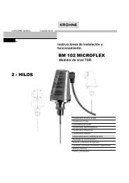
KROHN E1 2 3 4 5 61000KROHN E1 2 3 4 5 6kg/hkg900 7 8 6 3 20800700SN 586 677 /01-03MC H250/RR/ M9/K2 /ESK- Z600C K2 5.2 1.4571F CIV 25 1.4571500MD 1997400C2H50HD 0.93 kg/l300V 2.5 mPa.sT 23.5 C200P 0.4 MPaFI A 10253 PROFIBUS PA DEVICE (MBP INTERFACE & PA PROFILE 3.013.1 Software historyOPTIMASSIssued Signal Converter Application Program System IntegrationMonth/Year11/06Hardware'MFC300 SignalConverter with MBPInterface and PAProfile 3.01("Profibus PADevice")FirmwareV2.2.1/061117Hardware Software Driver Version• Simatic PCS7• Others• HW Config• OthersGSD(Manufacturer specific, forstandard DP/PA segmentcoupler )GSD(Manufacturer specific, forsegment coupler SK2/SK3 ofP&F)GSD(Profile specific, for standardDP/PA segment coupler)KR014511.GSDYP014511.GSDPA139742.GSDLaptop/ PC PDM A 6.0 DD 4511 0300 01Model Name asused in the GSD:"MFC300 (MBP)Rev. 1""YP0 MFC300(MBP) Rev.1""Flow,dens,temp3AI, 1TOT (PhyL1)"Laptop/ PCPactwareDTM(generic Flow DTM)0300_1030001_FDT12.exe3.2 PROFIBUS PA System ArchitectureControl system(PLC) Class 1masterPLCPLCPCEngineering or operationcontrol tool. Class 2 masterAnalogue I/OmodulePROFIBUS DP (up to 12 Mbit/s)Segmentcoupler/linkPowerSupplyPROFIBUS-PA100RPKR OHNE H250PROFIBUS-PA4-20 mAHART DeviceThe diagram above shows a typical instrumentation with PROFIBUS PA devices with MBP interfacein hazardous and non-hazardous locations, including connections of conventional devices(e.g. with 4-20mA signals) ina a PROFIBUS network.The PROFIBUS PA is normally connected to a segment coupler which, among other things,carries out the conversion to the PROFIBUS DP.Further information on the planning and operation of PROFIBUS PA networks can be found inthe KROHNE brochure “Fundamentals PROFIBUS” which can be downloaded from theKROHNE homepage http://www.krohne.com or contact “KROHNE Marketing”.22
3.3 Bus Connection - PROFIBUS PA DeviceFor a detailed description of the electrical connections of the MFC300 please refer to the OPTI-MASS Handbook.1D- D C- CDevice Internal Terminal NamesPA- PA+ PA- PA+External Bus ConnectionsSpur2D- D C- CDevice Internal Terminal NamesPA- PA+ PA- PA+External Bus ConnectionsTrunk inTrunk out3D- D C- CDevice Internal Terminal NamesPA+ PA- PA+ PA-External Bus Connections1 Single Spur2 Trunk In/Out3 Alternative wiring because the current linkage between the device and the PROFIBUS PAcable is not polarised.Note: Although the PROFIBUS MBP technology supports power supply via the PROFIBUS linethe “MFC300 PROFIBUS MBP interface” will operate only if the additional power supply for thedevice is connected / available.23
3.4 GSD FilesA “PROFIBUS GSD ZIP” file (e.g. GSD-31777815.zip) including both all KROHNE GSD files andadditional data files can be downloaded from the KROHNE homepage http://www.krohne.comor contact “KROHNE Marketing”. The GSD file contains information that will be needed forproject planning of the PROFIBUS communication network. The relevant data files (e.g.MFC300_n.bmp; MFC300_n.dib) must be loaded into the bus configuration system/master systembefore start-up of the bus system.The MFC300 PROFIBUS MBP Interface is according to the PROFIBUS PA Profile V 3.01. Thedevice supports two Ident-No.:• Ident-No. “4511hex” belongs to the KR014511.GSD / YP014511.GSD and includes the completefunctionality concerning the cyclic data exchange of the coriolis mass flow meterMFC300.• The application of the manufacturer independent Ident-No. “9742hex” (GSD file“PA139742.GSD”) provides interchange ability of devices, i.e. an exchange of coriolis massflow meters of different vendors.Please follow the instructions in the <strong>manual</strong> of the host supplier when installing the GSD Fileyou need and the additional files (MFC300_n.bmp and MFC300_n.dib) into the PLC. If separatedby the bus configuration system the device entry of the MFC300 PROFIBUS MBP Interface withPA Profile 3.01 will be located within the slave family PROFIBUS PA.3.4.1 Manufacturer specific GSD files: KR014511.GSD & YP014511 GSDThe KR014511.GSD file is for use with the standard DP/PA coupler and the YP014511.GSD fileis for use with the transparent DP/PA coupler SK2/SK3 of Pepperl & Fuchs (up to 12 MBaud onthe DP segment)Note: For devices with MBP interface there are always two types of GSD files in our GSD compilation:• One standard GSD file for a standard DP/PA segment coupler: file name: “KR….GSD”• One special GSD file specific for the segment coupler SK2/SK3 of Pepperl & Fuchs filename: “YP….GSD”It should be noted that both GSD files suport device functionality as described below:BlockNumberStandard-Configurationfunction block output: value + status)KR014511.GSDYP014511.GSDIdent-No. 4511Default unit:1 Mass Flow AI-FB kg/s2 Density AI-FB kg/m33 Medium Temperature AI-FB K4 Mass Totalizer Totalizer-FB kg5 Volume Totalizer Totalizer-FB m36 Mass Totalizer Totalizer-FB kg7 Volume Flow AI-FB m3/h8 Concentration 1 AI-FB %9 Concentration 2 AI-FB %10 Concentration Mass Flow 1 AI-FB kg/s11 Concentration Mass Flow 2 AI-FB kg/s24
AI = Analog Input Function BlockFB = Function BlockThere are separate settings to select the units for local display and PROFIBUS. Modifications ofthe units of the display will have no effect on the data transferred via PROFIBUS. A masterclass 2 tool is required to modify the units for PROFIBUS transfer.Important Notes:During network configuration the user has to define which function block outputs of the“MFC300 PROFIBUS MBP interface” should be transferred cyclically to the master. This isdone by a bus configuration tool (e.g. for PC-S7 from Siemens this will be done with the tool“HW- Config”). This tool offers the functions described as follows:1. It is possible to configure an “Empty” block (the code of an “Empty” block is defined as0x00) on each block number. This means, that for this block no data is transmitted in thecyclic data telegram.2. There is NO “Totalizer (TOT)” function block allowed on block position 1, 2, 3, 7, 8, 9, 10 and11! An “Analog Input (AI)” function block or an “Empty” block is allowed here only!Note: All codes supported of “Analog Input (AI)” - and “Totalizer (TOT)” – function blocks willbe found in the corresponding GSD files.3. There is NO “Analog Input (AI)” function block allowed on block position 4, 5 and 6! A“Totalizer (TOT)” function block or an “Empty” block is allowed here only!4. There is a choice of 7 different totalizer functions, which can be allocated to the blocks 4, 5and / or 6. The 7 functions are defined as follows:“Total”“SetTot + Total”“ModeTot + Total”“SetTot+ModeTot+Total”“SetTot”“ModeTot”“SetTot + ModeTot”cyclic transfer of the totaliser value with status to the mastercyclic transfer of the totaliser value with status to the master + cycliccontrol data from master to the device via the parameter SetTotcyclic transfer of the totaliser value with status to the master + cycliccontrol data from master to the device via the parameter ModeTotcyclic transfer of the totaliser value with status to the master + cycliccontrol data from master to the device via the parameters SetTot andModeTot (in the given order)cyclic control data from master to the device via the parameter SetTotcyclic control data from master to the device via the parameter ModeTotcyclic control data from master to the device via the parameters SetTotand ModeTot (in the given order)Both, the Byte SetTot and ModeTot are being sent cyclically from the Master to the device ifthese bytes are inserted as output data via the PLC configurator. The meaning of these controlbytes are as follows:25
SetTot:SetTot =0:SetTot =1:SetTot =2:SetTot ? 2:Totaliser is totalising.Totaliser will be reset to 0 and stays at 0 until SetTot is switched back againto 0. If the value of SetTot changes from “1” to “0” the totaliser starts countingfrom 0.Totaliser is set to the value defined by PresetTot. PresetTot can be written viaa acyclic master (totaliser in block 4 = Slot 4 Index 32; totaliser in block 5 =Slot 5 Index 32; totaliser in block 6 = Slot 6 Index 32). If the value of SetTotchanges from “2” to “0” the totaliser starts counting from the current valuedefined by PresetTot.not allowed. Value is ignored; totaliser remains in its last valid setting.ModeTot:ModeTot = 0ModeTot = 1ModeTot = 2ModeTot = 3totaliser totalises positive and negative values.totalises only positive values.totalises only negative values.totaliser is stopped, no totalization will be done.ModeTot = 248 totalises all values as positive (negative values will be multiplied with “-1.0”)ModeTot = 249 totalises all values as negative (positive values will be multiplied with “-1.0”)All other values of ModeTot are not allowed. Value is ignored; totalizer remains in its last validsetting.5. The standard block configuration may be changed by the customer but using the defaultsettings is highly recommended. If the standard block configuration should be changed bythe customer an acyclic master tool must be used to change the “channel parameter” valueof the block which should be connected to another transducer output value.3.4.2 Profile specific GSD file: PA139742. GSDThe functionality of the profile specific GSD file is limited. This GSD file includes only fourblocks:Block NumberStandard-Configuration(function block output value)PA139742. GSDIdent-No. 9742Defaultunit:1 Mass Flow AI-FB kg/s2 Density AI-FB kg/m33 Medium Temperature AI-FB K4 Mass Totaliser Totaliser-FB kgThe device has to be switched from “Manufacturer Specific” (full functionality) to “ProfileSpecific” (interchangeable basic configuration) by using a master class 2 tool (IDENT_NUM-BER_SELECTOR: Slot 0, Index 40 change byte value to 0). After this the device has to be projectedby using the PA139742.GSD file.3.4.3 Cyclic data exchangeDuring network configuration the user has to define which function block outputs of theMFC300 PROFIBUS MBP Interface should be transferred cyclically to the master. Network configurationwill be done using one of the GSD files described above. The order of transmission ofthe function blocks always remains the same even if a function block is defined as an “Empty”block (if so no function block output data will be sent to the master and all function block outputsfollowing the “Empty” block will move up one position).26
3.5 ProfileThe MFC300 PROFIBUS MBP Interface is based on PROFIBUS PA Profile Version 3.01 and supportsthe following blocks:• One Physical Block.This block contains the parameters defined in PA Profile 3.01.• One Transducer Block for coriolis mass flow devices.This block provides the parameters and functions defined in PA Profile 3.01.• Eight “Analog Input (AI)” function blocks: as default “Mass Flow”, “Density”, “MediumTemperature”, “Volume Flow”, “Concentration 1”, “Concentration 2”, “Concentration MassFlow 1” and “Concentration Mass Flow 2”.• Three “Totalizer (TOT)” function blocks: as default the first and the third totalizers willtotalize “Mass” and second one will totalize “Volume”.3.6 Data Structure of Function Block Output ValuesThe data structure of function block outputs consists of 5 bytes: a 4 byte float value (FloatFormat according IEEE Standard 754 Short Real Number) followed by a 1 byte status value. Ifall 11 function block outputs have been projected (see above), 55 byte will be transmitted.Float ValueFirst an example of the float formatByte n Byte n+1 Byte n+2 Byte n+3Bit7 Bit6 Bit7 Bit6 Bit7 Bit7VZ 2 7 2 6 2 5 2 4 2 3 2 2 2 1 2 0 2 -1 2 -2 2 -3 2 -4 2 -5 2 -6 2 -7 2 -8 2 -9 2 -10 2 -11 2 -12 2 -13 2 -14 2 -15 2 -16 2 -17 2 -18 2 -19 2 -20 2 -21 2 -22 2 -23Exponent Mantissa Mantissa MantissaExample:40 F0 00 00 (hex) = 0100 0000 1111 0000 0000 0000 0000 0000 (binary)Formula: Value = (-1)VZ * 2 (Exponent - 127) * (1 + Mantissa)Status ValueValue = (-1)0 * 2 (129 - 127) * (1 + 2 -1 + 2 -2 + 2 -3 )Value = 1 * 4 * (1 + 0,5 + 0,25 + 0,125)Value = 7,5The meanings of the status byte (unsigned integer) are described in the following tablesQuality Quality-Substatus LimitsGr Gr QS QS QS QS Qu Qu2 7 2 6 2 5 2 4 2 3 2 2 2 1 2 00 0 = bad0 1 = uncertain1 0 = good (Non Cascade)1 1 = good (Cascade) - not supportedStatus = bad0 0 0 0 0 0 = non-specific0 0 0 0 0 1 = configuration error0 0 0 0 1 0 = not connected0 0 0 0 1 1 = device failure0 0 0 1 0 0 = sensor failure0 0 0 1 0 1 = no communication (last usable value)0 0 0 1 1 0 = no communication (no usable value)0 0 0 1 1 1 = out of service27
Status = uncertain0 1 0 0 0 0 = non-specific0 1 0 0 0 1 = last usable value0 1 0 0 1 0 = substitute-set0 1 0 0 1 1 = initial value0 1 0 1 0 0 = sensor conversion not accurate0 1 0 1 0 1 = engineering unit violation (unit not in the valid set)0 1 0 1 1 0 = sub-normal0 1 0 1 1 1 = configuration error0 1 1 0 0 0 = simulated value0 1 1 0 0 1 = sensor calibrationStatus = good (Non-Cascade)1 0 0 0 0 0 = ok1 0 0 0 0 1 = update event1 0 0 0 1 0 = active advisory alarm (priority < 8)1 0 0 0 1 1 = active critical alarm (priority > 8)1 0 0 1 0 0 = unacknowledged update event1 0 0 1 0 1 = unacknowledged advisory alarm1 0 0 1 1 0 = unacknowledged critical alarm1 0 1 0 0 0 = initiate fail safe1 0 1 0 0 1 = maintenance requiredStatus = Limits0 0 = ok0 1 = low limited1 0 = high limited1 1 = constantCheck the first two quality bits in order to get the quality information of the measurementvalue:Good(non Cascade)Good(Cascade)Uncertainfunction block output value is ok and can be used without restrictionswill not be supported, because it is not applicable for the devicefunction block output value can be used but the accuracy can not be guaranteed(e.g. function block outputs value has been frozen or A/D converteris saturated or out of range)Badfunction block output value is bad - don’t use it for process control!The „Quality-Substatus“- and „Limit“-Bits will be used for further diagnostics or limit checking.Attention: The status should be monitored because a number will be transmitted even ifthe status of the measurement value is bad or uncertain. This is the only way to check thequality of the transmitted measurement values.3.7 DiagnosisIf the device internal diagnostic functions detect an error additional information will be sent tothe Master (for further information have a look at the UNIT_DIAG_BIT(i) definitions of the correspondingGSD-file).28
3.8 Display Paramters (PROFIBUS)(MFC300 PROFIBUS MBP Interface with PA Profile 3.01)For a detailed description please see ”MFC 300 (OPTIMASS) Handbook”. Some special settings concerningthe PROFIBUS features are easily operated via the local menu. Please see the following tables.A Quick SetupRef Display Description & SettingsA3A4ResetStation AddressThis menu function can be used to reset allerrors that are not removed automatically(power fail, counter overflow)A3.1 Reset Errorsstep 1: reset?No: Exit the functionYes Resets the errors and exits the function.The following reset menus for the counters (totaliser) are only available, ifthe quick access has been activated in the menu setup > device > quicksetup. Each counter (totaliser) can be activated for quick access independently.(for PROFIBUS Devices) the counter can bereset to zero in this menuA3.2 > FB4 Totaliser 1 step 1: reset counter?no: exits the function without resetyes: resets the counter and exits the function(for PROFIBUS Devices) the counter can bereset to zero in this menustep 1: reset counter?A3.3 > FB5 Totaliser 2No exits the function without resetYes resets the counter and exits the function(for PROFIBUS Devices) the counter can bereset to zero in this menustep 1: reset counter?A3.4 > FB6 Totaliser 3No exits the function without resetYes resets the counter and exits the function(only for PROFIBUS devices)A4 -> Station Address selects the address of the device at the PROFIBUSDP interface.Note:The PROFIBUS address can also be changed using the PROFIBUS service“set_slave_add”. The input range is 0...125 according to the PROFIBUS specification.Address 126 is the default address and cannot be set via thePROFIBUS service “set_slave_add” - use menu instead to reset to defaultaddress.B Test levelB3 InformationB3.5 PROFIBUSavailable if there is a PROFIBUS interface in existence; displays thebelow mentioned information about the PROFIBUS interface:KROHNE Ident No.Software Revision of the PROFIBUS softwareDate of Production29
C SetupC4 I/O TotaliserC 4.y Totaliser 1, 2 or 3Allows you to control the three PROFIBUS counters The three menusare identical so they are grouped together and their functions aredescribed in one go.C 4.y.1 Function of Totaliser Incremental Total Totalises only positive valuesDecremental TotalAbsolute TotalStop TotaliserAll As PositiveAll As NegativeTotalises only negative valuesTotalises positive and negative valuesTotaliser is stopped.neg. input values will be multiplied with"-1.0"pos. input values will be multiplied with"-1.0"C 4.y.2C 4.y.3C 4.y.4C 4.y.5MeasurementPreset ValueReset TotaliserError behaviour• Volume flow • Mass flow• Voncentration total1 • Concentration total2• Conc volume flow 1 • Conc volume flow 2(predefines a “threshold” using the High Limit value and the Low Limitvalue of the totaliser affected; the “THRESHOLD” bit will be set in thelong status information bytes of the PROFIBUS interface if the actualvalue of the totaliser is outside these limits. This can be also used as astatus output choosing the function "preset counter X”(The current value of the totaliser can be set to zero)Step 1: reset totaliser?no: exits the function without resetyes: resets the totaliser to zero and exits the function; totaliserwill restart counting at once(defines the behaviour of this function block in case of errors)totalization is continued based on thelast incoming value with good statushold meas. valuebefore the first occurrence of bad statusignore error:totalization is continued using the inputvalues despite the bad status. The statusis ignoredstop totalisertotalization is stopped during occurrenceof bad status of incoming valuesC 4.y.6information(The KROHNE Ident. No. of the circuit board, the software versionnumber and the production date of the circuit board will be displayed)Note:If you choose “y” = 1 all settings will effect FB 4 (Totaliser 1)if you choose “y” = 2 all settings will effect FB 5 (Totaliser 2)if you choose “y” = 3 all settings will effect FB 6 (Totaliser 3)30
Ref Display Description & SettingsC5 I/O PROFIBUS (This feature is available for PROFIBUS devices only.)Using the menu functions mentioned below you will be able to control basically the eight analogue inputblocks of this PROFIBUS device. These eight menus are identical so they are grouped together and theirfunctions are described in one go.C5.y.1MeasurementSelects the measurement (channel) for the analogue input block forthe PROFIBUS interfaceMass flow:TemperatureDensity: Concentration 1:Concentration 2: Concentration mass flow 2Concentration mass flow 1: Concentration volume flow 1Concentration volume flow 2 Sensor deviation:Sensor average:Drive energyTube frequency:Tube strainInner cylinder strain: Electronics temperature *Flow velocityVolume flowSupply*** This is the electronic temperature** This is internal supply voltage for the PROFIBUSC5.y.2 Time Constant Time constant for this function blockDefines the behaviour of this function block in case of errorsC5.y.3Error BehaviourHold Value:Ignore Error:last valid OUT value stored will be used asOUT valueOUT has the wrong calculated value and statusBad as calculatedReplace Value:“replacement value” will be used as OUT valueNote:If you choose “y” = 1 all settings will effect FB 1 (Analog Inp.1)if you choose “y” = 2 all settings will effect FB 2 (Analog Inp.2)if you choose “y” = 3 all settings will effect FB 3 (Analog Inp.3)if you choose “y” = 4 all settings will effect FB 7 (Analog Inp.4)if you choose “y” = 5 all settings will effect FB 8 (Analog Inp.5)if you choose “y” = 6 all settings will effect FB 9 (Analog Inp.6)if you choose “y” = 7 all settings will effect FB 10 (Analog Inp.7)if you choose “y” = 8 all settings will effect FB 11 (Analog Inp.8)C6 -> DeviceIn this menu all functions are grouped that have no effect on the measurement or any output directly.One lineDisplay shows one line of measurement onthis pageC6.3.1FunctionTwo linesDisplay shows two lines of measurement onthis pageThree linesDisplay shows three lines of measurement onthis page31
Ref Display Description & SettingsC6 Device ctd...C6.3.2C6.3.8C6.3.10C6.4 -> 2. Meas. pageMeasurement 1.lineMeasurement 2.line(Only available if thisline is activated)Measurement 3.line(Only available if thisline is activated)Mass flow:TemperatureDensity: Concentration 1Concentration flow 1 Diagnosis 1Diagnosis 2: Diagnosis 3Flow Velocity:VolumeFlowBargraph*Flow VelocityVolume Flow:Mass FlowTemperature:DensityConcentration 1: Concentration Flow 1Diagnosis 1: Diagnosis 2Diagnosis 3: FB4 Totaliser 1FB5 totaliser 2: FB6 Totaliser 3Operating Hours* Analogue display of the value selected for the first lineFlow VelocityVolume Flow:Mass FlowTemperature:Density Concentration 1:Concentration Flow 1 Diagnosis 1:Diagnosis 2 Diagnosis 3:FB4 Totaliser 1 FB5 totaliser 2:FB6 Totaliser 3Operating HoursIn case of a PROFIBUS device the second measurement page is meant to check the output values of thedifferent function blocks. Only PROFIBUS values can be selected here. The analogue inputs are shownwith exactly the value, as seen on the PROFIBUS.C6.4.1C6.4.2C6.4.3C6.4.4C6.4.5Measurement 1.lineFormat 1.lineMeasurement 2.lineFormat 2.lineMeasurement 3.lineFB1 Analog inp. 1 FB2 Analog inp. 2FB3 Analog inp. 3 FB4 Totaliser 1FB5 Totaliser 2 FB6 Totaliser 3FB7 Analog inp. 4: FB8 Analog inp. 5FB9 Analog inp. 6: FB10 Analog inp. 7FB11 Analog inp. 8Fixed number of digits after the decimal point or automatic, wherethe number of digits is automatically adjusted to the available space.FB1 Analog inp. 1 FB2 Analog inp. 2FB3 Analog inp. 3 FB4 Totaliser 1FB5 Totaliser 2 FB6 Totaliser 3FB7 Analog inp. 4: FB8 Analog inp. 5FB9 Analog inp. 6: FB10 Analog inp. 7FB11 Analog inp. 8Fixed number of digits after the decimal point or automatic, wherethe number of digits is automatically adjusted to the available space.FB1 Analog inp. 1 FB2 Analog inp. 2FB3 Analog inp. 3 FB4 Totaliser 1FB5 TOTALISER 2 FB6 Totaliser 3FB7 Analog inp. 4: FB8 Analog inp. 5FB9 Analog inp. 6: FB10 Analog inp. 7FB11 Analog inp. 8C6.4.6Format 3.lineFixed number of digits after the decimal point or automatic, wherethe number of digits is automatically adjusted to the available space.32
Ref Display Description & SettingsC6 Device ctd...C6.6 Special FunctionsC6.6.1Reset ErrorsThis menu function can be used to reset all errors, that are notremoved automatically (e.g. power fail)step 1:Reset?no: exit the functionyes: resets the errors and exits the function.In this menu all settings can be saved in different storage places)Save Settings?breakExit the menu without savingStep 1backup 1Saves the settings in the backup 1 storageplaceC6.6.2Save Settingsbackup 2Saves the settings in the backup 2 storageplaceGo on with copy? (Note: There is no possibility toundo this command!)Step 2NoYesExit function without savingCopy the actual settings to the selected storageplace and exits the function.Note: PROFIBUS interface settings will not be saved(in this menu all settings can be loaded from different storage places,where settings have been saved before)Load Settings?breakExits the menu without loadingC6.6.3Load Settingsstep 1factory settingsbackup 1backup 2Loads the settings from the deliveryLoads the settings from the backup1 storage place)Loads the settings from the backup2 storage place)step 2go on with copy? (Note: There is no possibility toundo this command!)Noexit function without savingYes copy the actual settings to the selected storageplace and exits the functionNote: PROFIBUS interface settings will not be loadedC6.8 Physical Block This menu is only available, if a PROFIBUS interface is presentSelects the PROFIBUS station address of the deviceC6.8.1Station AddressNote:The PROFIBUS address can also be changed using the PROFIBUSservice “set_slave_add”. The input range is 0...125 according to thePROFIBUS specification. Address 126 is the default address and cannotbe set via the PROFIBUS service “set_slave_add” - use menuinstead to reset to default address.33
Ref Display Description & SettingsC6 Device ctd...C6.8.2InformationGives information about the hardware version, software version andthe calibration/test date of this interfaceC6.8.3Diag. extensionC6.8.4 Diag. extension 2C6.8.5Diag. extension i.(intern)C6.9 quick setupGives a representation of the status information, that is also availableon the PROFIBUS interface. The status is displayed in hexadecimalformat.In this menu some settings in the Quick Setup can be activated. In the default configuration the settings inthe Quick Setup are activated.C6.9.1 reset totaliser 1C6.9.2 reset totaliser 2C6.9.3 reset totaliser 3DServiceThe reset can be activated in the Quick Setup to get a quick accessof the functionYes quick access activatedNo quick access not activatedThe reset can be activated in the Quick Setup to get a quick accessof the functionYes quick access activatedNo quick access not activatedThe reset can be activated in the Quick Setup to get a quick accessof the functionYes quick access activatedNo quick access not activatedThis menu is protected. You will need to use the service password to gain access.D2SystemD2.2 Service ParametersIn this menu all functions related to different data sets can befound.D2.2.1D2.2.2Cold startSave Factory DataResetting of the MFC300 can be done here but all changes up tothis point are automatically stored and cannot be discarded.step 1 reset?Noyesterminates the functionperforms the reset and leaves the programmingmodeCopies the actual data into the factory setting, this overwrites thefactory settings done during calibration)Step 1Step 2Save Settings?breakfactory settingsexits the menu without savingsaves the settings as factorysettingsgo on with copy? (there is no possibility to undothis command)No exit menu without savingYes copy the actual settings to the selectedstorage place.34
Ref Display Description & SettingsD2 System ctd...D2.2.4Identification NoSets a different device modus for the cyclic communication of thePROFIBUS interfaceMFC300complete functionality concerning the cyclic dataexchange of the coriolis mass flow meter MFC300is supported (including manufacturer specificextensions)Profileonly the profile defined functions concerning thecyclic data exchange are supported - no extrasD2.2.5PB Cold StartNo terminates the functionYes PROFIBUS cold start will be carried out atReset?once. The programming mode is terminatedNote:During a PROFIBUS cold start nearly all parameter values of thewhole device will be set to their default values (e.g. the PROFIBUSaddress will not be changed) without disconnecting an alreadyestablished connection to a PROFIBUS Master systemCurrent Device RevisionUse the display of the “MFC300 with PROFIBUS MBP Interface” to open the path:“test\information\Profibus” ( == menu B3.5)This menu will provide the following information:KROHNE Ident No.Software Revision of the PROFIBUS softwareDate of Production35
3.9 Technical DataHardwareSoftwarePhysicalPROFIBUS MBP Interfaceaccording to IEC 61158GSDGSD file can be downloaded from theKROHNE Homepagehttp://www.krohne.comConnection Independent of polarity Device profile PA Profile compact class B, V3.01Base current 10,5 mAAddress range0...126; default 1260 to 125 via “set_slave_add”0 to 126 via “Local Display”126 via “FACTORY_RESET = 2712”FDEyes: separate fault disconnectionelectronics providedLocal controllocal display and operator interface atdevice.Faultcurrent6 mA; (fault current = max.continuous current – basecurrent).SAPs2 MS1 SAPs - acyclic interface to PLC3 MS2 SAPs - the number of MS2 ServiceAccess Points is typically equal to themaximum number of master class 2 toolsStartingcurrent“Ex“approval< 12mA Function BlocksEEx ia IIC or EEx ib IIC/IIB,FISCO device(for details see“MFC 300 (OPTIMASS)Handbook”)1 PB1 TB8 AI3 TOT36
© KROHNE 12/2006 7.02265.22.00 Krohne reserves the right to make changes without prior noticeAustraliaKROHNE Australia Pty LtdQuantum Business Park10/287 Victoria RdRydalmere NSW 2116TEL.: +61 2 8846 1700FAX: +61 2 8846 1755e-mail: krohne@krohne.com.auAustriaKROHNE Austria Ges.m.b.H.Modecenterstraße 14A-1030 WienTEL.: +43(0)1/203 45 32FAX: +43(0)1/203 47 78e-mail: info@krohne.atBelgiumKROHNE Belgium N.V.Brusselstraat 320B-1702 Groot BijgaardenTEL.: +32(0)2-4 66 00 10FAX: +32(0)2-4 66 08 00e-mail: krohne@krohne.beBrazilKROHNE ConautControles Automaticos Ltda.Estrada Louis Pasteur, 230 C.P. 5606835 - 080 EMBU - SPTEL.: +55(0)11-4785-2700FAX: +55(0)11-4785-2768e-mail: conaut@conaut.com.brChinaKROHNE Measurement Instruments(Shanghai) Co. Ltd.9th Floor, Xujiahui International Building1033 Zhaojiabang RoadShanghai 200030P. R. ChinaTEL.: +86 21 6487 9611FAX: +86 21 6438 7110e-mail: info@krohne-asia.comCISKanex KROHNE Engineering AGBusiness-Centre Planeta, Office 403Marxistskaja-Street 3109147 Moscow/RussiaTEL.: +7(0)095-9117 165FAX: +7(0)095-9117 231e-mail: krohne@dol.ruCzech RepublicKROHNE CZ, spol. s r.o.Sobìšická 15663800 BrnoTEL.: +420 545 532 111FAX: +420 545 220 093e-mail: brno@krohne.czFranceKROHNE S.A.S.Les OrsBP 98F-26103 ROMANS CedexTEL.: +33(0)4-75 05 44 00FAX: +33(0)4-75 05 00 48e-mail: info@krohne.frGermanyKROHNE MesstechnikGmbH & Co. KGLudwig-Krohne-Str.D-47058 DuisburgTEL.: +49(0)203-301-0FAX: +49(0)203-301-10 389e-mail: info@krohne.deIndiaKROHNE Marshall Ltd.A-34/35, M.I.D.C.Industrial Area, H-Block,Pimpri Poona 411018TEL.: +91(0)202-7442020FAX: +91(0)202-7442020e-mail: pcu@vsnl.netIranKROHNE Liaison OfficeNorth Sohrevardi Ave.26, Sarmad St., Apt. #9Tehran 15539TEL.: ++98-21-874-5973FAX: ++98-21-850-1268e-mail: krohne@krohneiran.comItalyKROHNE Italia Srl.Via V. Monti 75I-20145 MilanoTEL.: +39(0)2-4 30 06 61FAX: +39(0)2-43 00 66 66e-mail: info@krohne.itKoreaKROHNE KoreaRoom 508 Miwon Bldg43 Yoido-DongYoungdeungpo-KuSeoul, KoreaTEL.: 00-82-2-780-1743FAX: 00-82-2-780-1749e-mail: krohnekorea@krohnekorea.comNetherlandsKROHNE AltometerKerkeplaat 12NL-3313 LC DordrechtTEL.: +31(0)78-6306300FAX: +31(0)78-6306390e-mail: postmaster@krohne-altometer.nlNetherlandsKROHNE Nederland B.V.Kerkeplaat 14NL-3313 LC DordrechtTEL.: +31(0)78-6306200FAX: +31(0)78-6306405Service Direkt: +31(0)78-6306222e-mail: info@krohne.nlNorwayKROHNE Norway A.S.Ekholtveien 114NO-1526 MossP.O. Box 2178, NO-1521 MossTEL.: +47(0)69-264860FAX: +47(0)69-267333e-mail: postmaster@krohne.noInternet: www.krohne.noSingaporeTokyo Keiso - KROHNE Singapore Pte. Ltd.14, International Business Park,Jurong EastChiyoda Building #01-01/02Singapore 609922SingaporeTEL.: ++65-65-67-4548FAX: ++65-65-67-9874South AfricaKROHNE Pty. Ltd.163 New RoadHalfway House Ext. 13MidrandTEL.: +27(0)11-315-2685FAX: +27(0)11-805-0531e-mail: midrand@krohne.co.zaSpainI.I. KROHNE Iberia, S.r.L.Poligono Industrial NiloCalle Brasil, n°. 5E-28806 Alcalá de Henares-MadridTEL.: +34(0)91-8 83 21 52FAX: +34(0)91-8 83 48 54e-mail: krohne@krohne.esSwitzerlandKROHNE AGUferstr. 90CH-4019 BaselTEL.: +41(0)61-638 30 30FAX: +41(0)61-638 30 40e-mail: info@krohne.chUnited KingdomKROHNE Ltd.Rutherford DrivePark Farm Industrial EstateWellingborough,Northants NN8 6AE, UKTEL.: +44(0)19 33-408 500FAX: +44(0)19 33-408 501e-mail: info@krohne.co.ukUSAKROHNE Inc.7 Dearborn RoadPeabody, MA 01960TEL.: +1-978 535-6060FAX: +1-978 535-1720e-mail: info@krohne.comOther RepresentativesAlgeriaArgentinaBelarusCameroonCanadaChileColombiaCroatiaDenmarkEcuadorEgyptFinlandGabonGhanaGreeceHong KongHungaryIndonesiaIvory CoastIranIrelandIsraelJapanJordanKuwaitLibyaLithuaniaMalaysiaMoroccoMauritiusMexicoNew ZealandPeruPolandPortugalRomaniaSaudi ArabiaSenegalSlovakiaSloveniaSwedenTaiwanThailandTurkeyTunisiaVenezuelaYugoslaviaOther CountriesKROHNE MesstechnikGmbH & Co. KGLudwig-Krohne-Str.D-47058 DuisburgTEL.: +49(0)203-301-0FAX: +49(0)203-301-389e-mail: export@krohne.deSubject to change without notice40