Certification Service Sira Certificatlon Service
Certification Service Sira Certificatlon Service
Certification Service Sira Certificatlon Service
- No tags were found...

You also want an ePaper? Increase the reach of your titles
YUMPU automatically turns print PDFs into web optimized ePapers that Google loves.
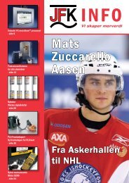
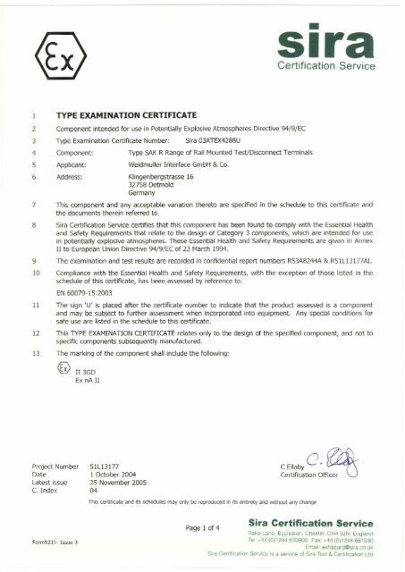
•sira<strong>Certification</strong><strong>Service</strong>TYPE EXAMINATION CERTIFlCATEComponent intended for use in Potentially Explosive Atmospheres Directive 94/9jECType Examlnation Certificate Number: <strong>Sira</strong> 03ATEX4288UComponent: Type SAK R Range of Ra!1 Mounted Test/Disconnect TenninalsApplicant: Weidmuller Interface GmbH & Co.Address: Klingenbergstrasse 1632758 DetrnoldGermanyThis component and any acceptable variation thereto are speclfled in the schedule to this certiflcate andthe documents therein referred to.<strong>Sira</strong> CertiflCaOOn <strong>Service</strong> certifles that this component has been found to comply with the Essential Healthand Safety Requirements that relate to the design of Category 3 components, which are intended for usein potentially explosive atmospheres. These Essential Health and Safety Requirements are given in AnnexII to European Union Directive 94/9/EC of 23 March 1994.The examination and test results are recorded in confidential report numbers R53A8244A & R51L13177AI.10 Compfiance with the Essential Health and Safety Requirements, with the exception of those Iisted in theschedule of this certlflcate, has been assessed by reference to:EN 60079-15:200311 The sign 'u' is placed after the certificate number to indicate that the product. assessed is a componentand may be subject to further assessment when incorporated into equipment. Any special oonditions forsafe use are Iisted in the schedu1e to this certiftCate.12 This TYPE EXAMINATION CERTIFICATE relates only to the design of the specified component, and not tospecific components subsequently manufactured.13 The marklng cf the component shall indude the foflowing:~ 113GDEx nA 11Project NumberDatelatest issueC. Index51L131771 October 200425 November 200504CEllabYO, ~<strong>Certification</strong>This certificate and its sc:tIeOJIes may ooIy be reproduced In its entIrety and without any mangeOff~Form9219 Issue3<strong>Sira</strong> <strong>Certificatlon</strong> <strong>Service</strong>Page 1 of4Rake Lane. Eccleston, Chester, CH4 9JN, EnglandTel' .•.44 (0)1244 670900 Fax: .•.44 (0)1244 681330Email' 6xhazardOsirs_co_uk<strong>Sira</strong> Cerlificalion <strong>Service</strong> is a serw::8 of <strong>Sira</strong> Test & Certrhcabon ltd
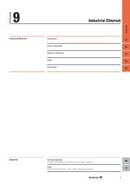
•Sifa<strong>Certification</strong> <strong>Service</strong>SCHEDULETYPE EXAMINATION CERTIFICATE NUMBER:<strong>Sira</strong> 03ATEX42BBURe-issued 25 November 2005 to inducle the changes described in report "umber R51L131nAI and tochange the certlficate template.13 DESCRIPTION OF COMPONENTThe Type SAK R Range of RaU Mounted TestjDisconnect Terminals comprise a single pole feed-throughterminal assembly, with disconnection link that is mounted Into a moulded polyamide PA66 or melamineinsulation housing. Each terminal assembly consists of a tin-plated, copper/zinc, split, current bar, whichfarms a knite blade contact. Thls is fitted wlth a zinc-plated steel, sliding yoke and screw at each end.When the screw Is tlghtened, the yake is compressed against the current bar and serrations incorporatedin Öle surface prevent slippage of the conductor.The disconnection link conslsts of a polyamide PA66 insulated, hinged tever, which ls fitted with a tinplated,copperltln, leaf spring contact. The disconnection link is operated by an upward movement of thehlnged contact lever; this breaks the connection between the two, !mife contacts.A polyamide PA66 Insulated cover is fitted in the moulding to hold and shield the main knife terminals.Self·deformation is ineorporated in the design when the serews are tightened down, this is used toprovide an automatie and progressive anti·rotation/anti·vibration locking effect.On both the 32 mm (SAK R) & 15 mm (SAK R 15) rail versions, a f1at section, stainless steel spring isIocated in a recess at the foot of the terminal housing, which allows it to be dipped onto a TS32 or TS15assembty rail respectivefy. A natural spring effect is deslgned into the plastic moulding of Öle 35 mm(SAK R 35) rail version to alJow it to be dipped onto a TS35 assembly rail.The following terminals are covered:Terminal Type Voltage Current Minimum Maximum Terminal reslstancerating rating cable slze cable size (mn @ 20·C)(V) rÄl (mm') (mm') (see note below)SAK R (oolvamlde PA66 400 10 0.5 4 2.66SAK R (melamlne 400 10 0.5 4 2.3BNote: When any cf the above tenninals are fitted inside jundion boxes, the terminal resistance figure to beu.sed for the purpose of assessing the maximum power dissipation is as listed in table above.The voltage rating Is an absolute condition of use as stated In Table 7 of EN 50021: 1999. The eurrentrating Is not an absolute flQure but is the recommended value when used in a general purpose junctionbox or marshalling box with cables having the following ratings:Cable Size mm 0.5 1 1.5 2.5 4Maximum Current A 5 10 10 10 10Higher currents may be permitted subject to individual examlnation of each specific application.Date 1 October 2004latest 25 November 2005issueThis certificate and Its sdledules may only be reproduced in its entirety and wlthout any changePage 2 of 4 <strong>Sira</strong> Certiflcatlon <strong>Service</strong>Form92191ssue 3Rake lane.ECCIestOll, Chester, CH4 9JN, EnglandTel:.44 (0)1244 670900 Fax: +44 (0)12 .•.•• 681330Email' exhazardOsira ccwkSefVice IS a service 01 $ira Test & Certihcaüon Ud<strong>Sira</strong> Cenifiealioo
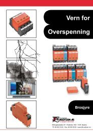
sira•<strong>Certification</strong> <strong>Service</strong>SCHEDULETYPE EXAMINATION CERTIFICATE NUMBER:5ira 03ATEX4288UThe marking is either moulded loto the body cf the terminal cr "tampo" printed onto it.All the terminals may be used in associatlon with Type QB 2, QB 3 cr QB4 (two way, three way or fourway respectively) cross-connectors and/or partitions, in which case, the voltage and current ratings areunchanged. In addition, all the terminals may be used in assoclatlon with AP end plates. The terminalassembly is to be damped in pface, at both ends, uslng either a Weidmuller, Type EK earth terminal, orossocioted Type EW (15, 15/2 o. 35), EWK(1 o. 2), WEW (35/1 Of 35/2) end bracket respeclively.14 DESCRIPTIVE DOCUMENTS14.1Drawing Rev. Sheet Date Title4 36258 0 1 of 1 11 Jun 03 SAK R (TS32) Terminal- Polyamide PA66436418 0 1 cf 1 31 Mar 04 SAK R 35 Terminal- Polyamide PA664 36406 0 1cf 1 31 Mar 04 SAK R 15 Terminal- Polyamide PA664 36233 0 1 cf 1 14 May 03 Q8 2-4 eross-connection Comb2 04546 12 1cf 1 02 Nov 05 SAK R Marking Details4 36260 0 10fl 12 Jun 03 AP End Plate14.2 Report numbers R53A8244A & R51L13177AI15 SPECIAL CONDmDNS FOR SAFE USE15.1 The end terminal shall be covered with the associated Type AP end plate and the terminal assemblyc1amped in place at both ends, using either a Weidmutler, Type EK earth terminal or associated endbrackets types EW (15,15/2 o. 35), EWK(1 o. 2) 000 WEW (35/1 Of 35/2) respeclively.15.2 Where wire sizes that are smaller than 0.5 mm 2 are used, a climped lug or femJle with a minimum size of0.5 mm 2 shall be fitted to the wire.15.3 Except where shown in a certJficate as belng internal wiring of apparatus, not more than one sIngle ormultiple strand lead shalt be connected into either side of any terminal, unless multiple conductors havebeen joined in a suitable manner, e.g. two conductors into a single insulated crimped boot lace ferrule.15.4 Any wlres that are connected to the terminals shatl be insulated for the appropriate voltage and thisinsulation shall extend to within 1mm of the metal of the telTTllnal throat.15.5 All telTTlinal screws, used or unused, shall be tightened down.15.6 The telTTlinais shal1 be installed on the relevant mounting rail:TypeRaUStandardSÄKR EN 60715:2001SÄ" R 15 EN 60715:2001SAKR 35 EN 60715:2001Weldmuller rail referenceTS32TS15TS3515.7 The minimum aeepage and dearance distances between the installed terminals and adjacent exposedfaces of equipment, endosure walls and covers shall be 5 mm and 4 mm respectlvely.Date 1 October 2004latest issue 25 November 2005This certificate and its sd1edu1es may only be reproduced in it5 entirety Md without any changeForm9219Issue3Page 3 cf 4<strong>Sira</strong> <strong>Certificatlon</strong> <strong>Service</strong>Rak.e Lane. Eccleslon, Chester. CH4 9JN. EnglandTel: +44 (0)1244 670900 Fax; +44 (0)1244 681330Email; exhazardOsira.co.uk.<strong>Sira</strong> CertfficafiQn <strong>Service</strong> is a service 01 Sire Tesl &. CertificatiOn Lid
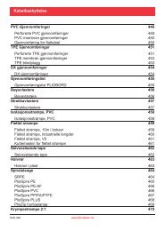
•Sifa<strong>Certification</strong> <strong>Service</strong>SCHEDULETYPE EXAMINATION CERTIFICATE NUMBER:<strong>Sira</strong> 03ATEX4288U15.8 The terminals sllall never be exposed to temperatures that are outside cf the following range:MaterialTemperatureRangePol amide PA66 -soDe to +90OCMelamine KrG sooe to +90°CIn addition, they shalJ only be installed and wlred with cable in a temperature range of -lOoe to +80°C.When these terminals are used in an atmosphere that contains combustible dust, they shall be installee!15.9inside an enclosure that has been suitably certlfted for use In this environment by a notifled l::xx:Iy.The tightening torque applied to the terminal screws shall be between 0.5 Nm and 1 Nm.15.1015.11 The sUPPIy to the Type SAK R Range of Rail Mounted Test/Disconnect Terminals shall be switched offwhen the disconnectjconnect fadlity is used i.e. during upward downward movement of theordisconnection lever assembly.Where the terminals are 5ubjected 15.12 to excessive vibration and vertically mounted, they shall be mountedwith the disconnection lever hlnged at the bottam.All of the Type QB cross-connectors shall be Iimited 15.13 to the same current rating as the related terminal andshall not be used with currents In excess of this value.Where the prong of a Type QB cross-connector is used 15.14 in a terminal way, a further single conductor of1 mm 2 minimum cross-sectional area may be connected to the same terminal way on top of the prang.TIle Type QB cross-connector shall be fitted with the angled insulation on the aoss-connecting 15.15 armInclined upwards towards the top of the terminal block.All Type QB cross-connectors shall be isolated from 15.16 adjacent terminals and other Type QB crossconnectorsuslng AP end plates.16 ESSENTIAL HEALTH AND SAFETY REQUIREMENTS (EHSRs)The relevant EHSRs that are not acklressed by the standards listed in this certificate have been identifiedand Individually assessed in report numbers R,53AB244A & R51L131nAl.17 CONDmONS OF CERTIFICAßON17.1 The use of this certificate is subject to the Regulations Applicable to Holders of <strong>Sira</strong> Certlficates.17.2 Holders of type-examination certificates are required to comply with the production control requirementsdeflned in Article 8 of directive 94/9/EC.Date 1 October 2004tatest issue 25 November 2005This certiflcate and its schedules may only be reproduced In Its enbrety and without any changeFmn9219 Issue 3Page 4 er 4 <strong>Sira</strong> <strong>Certificatlon</strong> <strong>Service</strong>Rake Lane. Eccleston. Chester. CH4 9JN. EnglandF"alC: +44 (0)1244 681330Tel' +44 (0)1244 670900Email' eJ:hazardOsira oo,uk<strong>Sira</strong> Cer1ificalion ServiCe IS a service 01 <strong>Sira</strong> Test & Certmcation Ud