1998 DESIGN AND VALIDATION RNN - Nearfield Systems Inc.
1998 DESIGN AND VALIDATION RNN - Nearfield Systems Inc.
1998 DESIGN AND VALIDATION RNN - Nearfield Systems Inc.
- No tags were found...

Create successful ePaper yourself
Turn your PDF publications into a flip-book with our unique Google optimized e-Paper software.
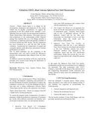
<strong>DESIGN</strong> <strong>AND</strong> <strong>VALIDATION</strong> OF A GENERALPURPOSE NEAR-FIELD ANTENNA MEASUREMENTFACILITY FOR THE ROYAL NETHERL<strong>AND</strong>S NAVYMart Hagenbeek & Daniël Janse van RensburgRoyal Netherlands Navy, SEWACO-EstablishmentPO Box 10 000Den Helder, The NetherlandsTel: +31 (0)223 656 221, Fax: +31 (0)223 656 273<strong>Nearfield</strong> <strong>Systems</strong> <strong>Inc</strong>.1330 E. 223 rd Street Bldg. 524Carson, CA 90745 USA(310)518-4277e-mail: drensburg@nearfield.comABSTRACTThis paper describes a new multi-purpose planar &cylindrical near-field antenna test facility installed at theRoyal Netherlands Navy (<strong>RNN</strong>). In this paper anoverview is given of the initial list of requirements thatwas generated and the process of selecting the best typeof measurement facility to address these. A descriptionof the facility is given and an outline of the accuracy ofthe planar/cylindrical near-field scanner is presented. Thepaper contains details of the extensive validationprogram and measured data demonstrating theperformance of the system.Keywords: Near-field, General purpose antennafacility, Cylindrical near-field.1. INTRODUCTIONIn this paper a new multi-purpose planar & cylindricalnear-field antenna test facility installed at the RoyalNetherlands Navy, is described. This antenna test facilitywas designed and built for the evaluation of alloperational microwave antennas currently used in theRoyal Netherlands Navy. In this paper an overview isgiven of the initial list of requirements that wasgenerated and the process of selecting the best type ofmeasurement facility to address these (i.e. outdoor farfield,compact range or near-field). Complicating factorslike the wide frequency range (.5 to 40 GHz) and thewide range of antenna dimensions (from 10 cm circularapertures to 8m rectangular array apertures) areaddressed. Dealing with high radiated power levels fromphased array radar antennas was also considered and thisis described from both a shielding and absorber point ofview. A description of the facility is given and an outlineof the accuracy of the planar/cylindrical near-fieldscanner (built by NSI) is presented. The paper containsdetails of the extensive validation program and measureddata demonstrating the performance of the system will bepresented. For the latter purpose a reference antennasupplied by the European Space Agency was used, aswell as other operational antennas. Lessons learnt duringthe validation exercise, especially in the field of accuracyenhancements with a laser-system and in the comparisonbetween planar and cylindrical data will be presented.Section 2 contains an overview of the originalrequirement that drove the procurement of the facility. InSection 3 a description of the system tradeoffs ispresented. The near-field system achieved specificationsare described in Section 4 and validation tests aredescribed and results presented in Section 5.2. ROYAL NETHERL<strong>AND</strong>S NAVYREQUIREMENTThe Netherlands Navy has a wide range of microwaveantennas in use on their fleet. The applications vary andinclude low-frequency long-range search radar antennas,high-frequency tracking radar antennas, EW -antennas1
and antennas for satellite communications. Theoperational antennas are refurbished regularly and thisprocess requires the removal of the unit from theplatform every 5 to 6 years of service. This service isprovided by the SEWACO-Establishment, where allparts are inspected, repaired and finally tested before it isreinstalled. The final testing of antennas was for yearslimited to checking the mechanical dimensions andalignment and only when a serious problem was detectedwere the antenna patterns measured. In these cases theantennas were sent to an outdoor range which is locatedmore than 160km away from the maintenance facility.These restrictive conditions and a continuous increase inthe complexity and performance of systems lead to theformulation of a need for an indoor test facility as part ofthe Navy maintenance facility. In order to address thewide range of antennas and also the range of parametersof interest for the Navy the following technicalrequirements were compiled:Frequency Range:Typical antenna gain:Antenna aperture size:Antenna weight:Max Radiated Power:Side lobe-level:1GHz to 35GHz7dBi to > 40dBi10cm to 8m1kg to almost 10000kgSeveral kilowatts-50dBThe objective was also set to test and evaluate theantennas during their operational lifecycle to ensurecontinued performance. The facility would therefore playa very active role in scheduled maintenance tasks and notonly serve as a one time evaluation tool. It was alsodecided that the test facility should be located in a newbuilding co-located with all the workshops for radar, firecontroland EW -systems. (The advantage here was thatthe design of a new building was not finalized at thattime so that it could be customized for some of therequirements for an antenna test site.)3. SYSTEM TRADEOFFSThe initial objective of the Navy was to design anoutdoor far-field test range. This would have been in linewith the historical approach and appeared to be a lowrisk option. The disadvantage of this approach was thelimited available real estate and the growing number ofbuildings that would have impeded measurementaccuracy. A growing concern for external radarinterference and security aspects also detracted from anoutdoor facility and eventually lead to the decision to optfor an indoor system.This decision ruled out a far-field approach and thereforea compact range or near-field test facility had to beconsidered. In order to gain as much information aboutthese as possible a number of facilities were visited andvaluable information was obtained in this way. It wasconcluded that the main advantage of a compact range isthe that it provides a real-time antenna response. Thedisadvantages are the size of the reflector(s) and therequirement for high power absorber on all the walls ofthe chamber (for high power testing). Initial calculationspointed out that for the Navy applications a reflector witha diameter of at least 15m would have been required,which in turn would have dictated a chamber with totalabsorber area of about 3000m². These facts indicated thatthe compact range would have exceeded the availablebudget by far.Considering planar near-field measurements theadvantage of having the AUT stationary was obvious. Nopositioner was required and the required space was smallenough so that it could be incorporated in an existingbuilding with less absorber and only limited areascovered with high power absorber. The disadvantages,however, are that no real-time data can be measured andfar-field data can only be calculated after completion of acomplete near-field scan. The angular limitation of aplanar near-field facility should also be noted. Acombination planar/cylindrical near-field rangeovercomes this problem though.This information indicated that a near-field system bestmet the requirements of the Royal Netherlands Navy andcould be built on the most cost-effective base. Thedecision was made to continue the procurement for anear-field test facility for antenna measurements and anorder was placed for a shielded anechoic chamber and aseparate order was placed for a complete near-field testsystem,including scanner, azimuth-positioner, RFequipmentand a control- and processing system. Thecontract for the building was extended with specificrequirements for foundation, cooling system, power anda hoisting system.4. SYSTEM DESCRIPTION4.1. SHIELDED ANECHOIC CHAMBERDESCRIPTION & SPECIFICATIONThe shielded anechoic chamber built by EEMC for <strong>RNN</strong>consists of a free-standing steel structure to which wallpanels were mounted. These panels are a foam-filledmetal sandwich construction (refrigeration panels wereused) to ensure a complete metallic enclosure around the2
near-field test system. Main dimensions of the chamberare 14m(l) x 11m(w) x 9.5m(h) and it has two 7m highautomatic access doors as shown in Figure 1. A separateshielded Control Room is located along one of the sidewalls.Points of special interest are the large doors for theAUT's, the moving ceiling (visible in Figure 2) foraccess of the hoisting system and the in- and outlets forthe cooling system. The chamber was constructed in sucha way that a shielding of at least 40dB could be obtainedfor frequencies between 1 GHz and 40 GHz. The coolingsystem was designed to assure a stable temperaturewithout large stratification over the scanner height evenunder high transmit power conditions. The inside of theshielded room is covered with absorber to preventreflections from the walls. Special attention was given tonew designed high power absorber in an area on the backwall. These absorbers are air-cooled and capable towithstand power levels more than 1.5 W/cm² (about10W/sq.in). Delivery of the absorber and measurementof the shielding and reflectivity performance was doneby Emerson & Cumming, a subcontractor from EEMC.4.2. NEAR-FIELD FACILITYDESCRIPTION & SPECIFICATIONThe near-field measurement facility built by NSI for<strong>RNN</strong> is a planar and cylindrical combination range. Theplanar scanner and azimuth positioner are located on asolid T-shaped foundation, 1.5m thick, laid on a separatesand-layer isolated from the rest of the building tosuppress vibrations. The planar scanner (depicted inFigure 3) has a total probe travel of 9m(x) x 6.4m(y) andhas a planarity of better than 25µm rms. The scanner alsoallows an additional 2m movement of the tower into acorner “pocket” of the chamber to hide the structure incases where the chamber is to be used for EMC typemeasurements. The scanner has a structure monitoringlaser feedback system that allows regular checking of themechanical integrity and active position feedback for theprobe carriage. The scanner is also fitted with highpower absorber to measure active antennas operating atfull radiated power. The azimuth positioner is mountedon a heavy duty linear slide which allows adjustment ofthe AUT to probe separation distance and also is used astransportation facility of antennas into the chamber (thecrane does not reach the full depth of the chamber).The RF system is based on a dual source HP8530 systemwith remote mixers and allows operation up to 40 GHz.It has a pulse capability allowing pulsed RFmeasurement and is reconfigurable for AUT receive orAUT transmit. A pin-diode switch matrix allowsmeasurement of four ports on the antennasimultaneously. The scanner, RF equipment and laserequipment is controlled by NSI software.The facility has proven performance specifications thatallow gain to be measured with an uncertainty of 0.25dB,-45dB side lobes with an uncertainty of 3dB, -30dBcross-polarization levels with an uncertainty of 3dB andboresight accuracy to within 0.02 degrees uncertainty.These performance figures were verified using a numberof different antenna types operating in differentfrequency bands.5. <strong>VALIDATION</strong> TEST RESULTSValidation of the <strong>RNN</strong> planar/cylindrical near-fieldfacility consisted of three separate tests. The first(Antenna #1) was the testing of a Navy dual band (X &Ka-band) tracking antenna for which far-field radiationpattern data was available. The second (Antenna #2) wasthe testing of an ESA/ESTEC X-band (VAST12) offsetreflector antenna (shown mounted in the chamber inFigure 4) for which comparative spherical near-field testdata was available. The third (Antenna #3) was an L-band Navy linear array (shown mounted in the chamberin Figure 5) which was chosen to evaluate the lowfrequency performance of the facility. The philosophy ofthe validation exercise was to measure a host of antennasin different configurations in both planar and cylindricalmodes and different frequency bands and to performmore than one inter-range comparison to improveconfidence in the facility performance.For Antenna #1 (the dual band tracking antenna) thethree ports on the unit were measured simultaneouslyduring a single planar near-field scan. From this datasum and difference patterns were extracted andcompared to far-field pattern data. Measurements wereperformed for the antenna in different configurations inboth frequency bands and a NIST 18 term error budget[1] was compiled based on these tests.For Antenna #2 radiation patterns were measured for theantenna mounted upright, 90 degrees rotated and 10degrees offset in azimuth in planar near-field mode. Theradiation patterns were also measured in cylindrical nearfieldmode. This data was compared to radiation patterndata obtained from spherical near-field results obtainedat another test facility. Measurements were performedfor multiple AUT to probe separation distances in orderto ensure acceptable levels of reflection from the probestructure. RF leakage tests and scan aperture truncationtests were performed. In order to check chamberreflection levels multiple AUT down range locations3
were again used for testing, while keeping the probe toAUT separation distance fixed. For this frequency band18-term error budgets were compiled for antenna gain, -45 dB side lobe level, -30 dB cross-polarization levels,beamwidth and boresight error. In Figure 6 comparativeradiation pattern data is shown for Antenna #2 asobtained in the <strong>RNN</strong> facility. The patterns shown are forthe AUT mounted in the normal fashion and rotated inazimuth by 20 degrees.6. CONCLUSIONWe have described in this paper what the requirementswere for an antenna test facility for the RoyalNetherlands Navy. The typical systems tradeoffs thatwere performed have been described and the fact that aplanar/cylindrical near-field test facility was chosen toovercome the fundamental angular limitation of a planarnear-field facility was pointed out. The facilitycharacteristics were presented and the validation processdescribed. Overall it can be stated that the facility is ageneral purpose test site allowing a wide range ofantennas to be tested and the extensive validationprogram has allowed detailed characterization of errors.Inter-range comparison data wil be presented todemonstrate the successful operation of the facility.REFERENCES[1] A C Newell, ”Error Analysis Techniques for PlanarNear-Field Measurements”, IEEE Trans. Antennas &Propagation, Vol. 36, No. 6, pp 754-767, June 1988.4
8. FIGURESFigure 1 A view of the Dutch Navy facility with the 7m automatic access doors open.Figure 2 The chamber slotted ceiling allowing crane access is shown.5
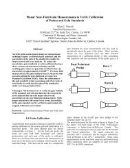
Figure 3 A drawing of the 9m x 6.4m planar scanner.Figure 4 The ESA/ESTEC Vast12 antenna (used for chamber validation) is shownmounted in the chamber. Note the high power probe absorber.6
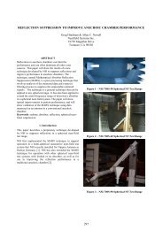
Figure 5 The linear array (Antenna #3) shown mounted in the <strong>RNN</strong> chamber.Figure 6 Far-field azimuth reference pattern and pattern for the AUT #2 offset by -20degrees in azimuth are shown superimposed as part of the system validation testing. (Theoffset pattern is shown shifted back to 0 here for comparison purposes.)7