CADD 1 Legacy Operation Manual
CADD 1 Legacy Operation Manual
CADD 1 Legacy Operation Manual
- No tags were found...

You also want an ePaper? Increase the reach of your titles
YUMPU automatically turns print PDFs into web optimized ePapers that Google loves.
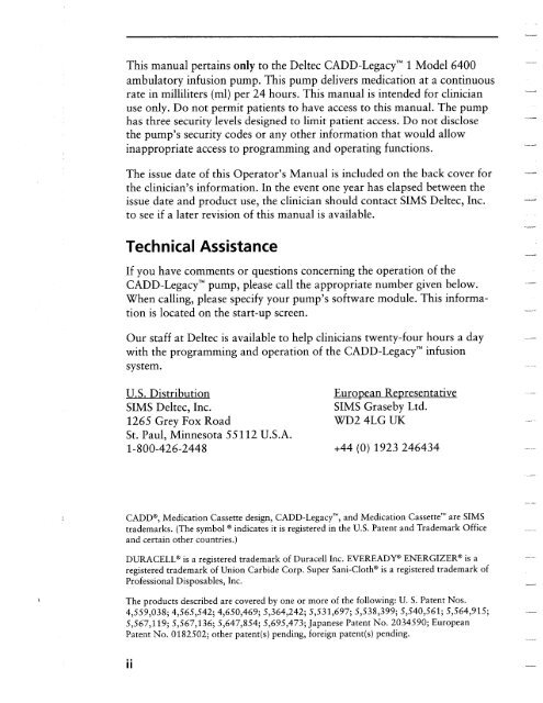
-This manual pertains only to the Deltec <strong>CADD</strong>-<strong>Legacy</strong>’” 1 Model 6400ambulatory infusion pump. This pump delivers medication at a continuousrate in milliliters (ml) per 24 hours. This manual is intended for clinicianuse only. Do not permit patients to have access to this manual. The pumphas three security levels designed to limit patient access. Do not disclosethe pump’s security codes or any other information that would allowinappropriate access to programming and operating functions.The issue date of this Operator’s <strong>Manual</strong> is included on the back cover forthe clinician’s information. In the event one year has elapsed between theissue date and product use, the clinician should contact SIMS Deltec, Inc.to see if a later revision of this manual is available.Technical AssistanceIf you have comments or questions concerning the operation of the<strong>CADD</strong>-<strong>Legacy</strong>’” pump, please call the appropriate number given below.When calling, please specify your pump’s software module. This informationis located on the start-up screen.-----.--_----_Our staff at Deltec is available to help clinicians twenty-fourwith the programming and operation of the <strong>CADD</strong>-<strong>Legacy</strong>’”system.hours a dayinfusion-U.S. DistributionSIMS Deltec, Inc.126.5 Grey Fox RoadSt. Paul, Minnesota 55112 U.S.A.l-800-426-2448Eurooean RenresentativeSIMS Graseby Ltd.WD2 4LG UK+44 (0) 1923 246434---_--_--~~--_ .---<strong>CADD</strong>@, Medication Cassette design, <strong>CADD</strong>-<strong>Legacy</strong>’“, and Medication Cassette” are SIMStrademarks. (The symbol @ indicates it is registered in the U.S. Patent and Trademark Officeand certain other countries.)DURACELL@’ is a registered trademark of Duracell Inc. EVEREADY@ ENERGIZER@ is aregistered trademark of Union Carbide Corp. Super Sani-Cloth@ is a registered trademark ofProfessional Disposables, Inc.The products described are covered by one or more of the following: U. S. Patent Nos.4,559,038; 4,565,542; 4,650,469; 5,364,242; 5,531,697; 5,538,399; $540,561; 5,564,915;5,567,119; 5,567,136; 5,647,854; 5,695,473; Japanese Patent No. 2034590; EuropeanPatent No. 0182502; other patent(s) pending, foreign patent(s) pending.ii
Read this entire Operator’s <strong>Manual</strong> before operating the<strong>CADD</strong>-<strong>Legacy</strong>’” ambulatory infusion pump.Failure to properly follow warnings, cautions, and instructions couldresult in death or serious injury to the patient.Warnings00This Operator’s <strong>Manual</strong> should be used by clinicians only. Donot permit patients to have access to this manual, as the informationcontained would allow the patient complete access to allprogramming and operating functions. Improper programmingcould result in death or serious injury to the patient.For those patients who are likely to be adversely affected byunintended operations and failures, including interrupted medicationor fluid delivery from the device, close supervision andprovision for immediate corrective action should be provided.If the pump is used to deliver life-sustaining medication, anadditional pump must be available.The pump is not to be used for delivery of blood or cellularblood products.If the pump is dropped or hit, inspect the pump for damage. Do notuse a pump that is damaged or is not functioning properly. ContactCustomer Service to return the pump for service.Do not administer drugs to the epidural or subarachnoid spaceunless indicated for such use. To prevent the infusion of drugsthat are not indicated for epidural or subarachnoid space infusion,do not use administration sets that incorporate injectionsites.0If a reservoir, cassette, or administration set is used for drugdelivery into the epidural or subarachnoid space, clearly differentiatesuch reservoirs, cassettes, or administration sets from thoseused for other routes of infusion, for example, by color coding,or other means of identification.. . .III
. .Prior to starting infusion, inspect the fluid path for kinks, aclosed clamp, or other upstream obstructions, and remove anyair to prevent air embolism.-Do not use rechargeable NiCad or nickel metal hydridebatteries. Do not use carbon zinc (“heavy duty”) batteries.(NiMH)Always have extra newEnsure that the batterybatteries available for replacement.door is securely latched.Ensure that the cassette is properly attached.Close the fluid path tubing with the clamp before removing thereservoir or administration set from the pump.Use only <strong>CADD</strong>@ Extension Set with Anti-Siphon Valve or a<strong>CADD</strong>@ Administration Set with either an integral or an Add OnAnti-Siphon Valve to protect against unregulated gravity infusionthat can result from an improperly attached reservoir or mayresult in delivery inaccuracies.Use of a syringe with the <strong>CADD</strong>@ Administration Set may resultin UNDER-DELIVERY of medication. Syringe function can beadversely affected by variations in plunger dimension and lubricity,which can result in greater force required to move the syringeplunger. A syringe plunger will lose lubrication as it ages and, asa result, the amount of under-delivery will increase which couldon occasion, be significant. Therefore, the type of medicationand delivery accuracy required must be considered when using asyringe with the <strong>CADD</strong>@ pump.-_--._.._~_.Clinicians must regularly compare the volume remaining in thesyringe to the pump’s displayed values such as RES VOL andGIVEN in order to determine whether under-delivery of medicationis occurring and if necessary, take appropriate action.System delivery inaccuracies may occur as a result of back pressureor fluid resistance, which depends upon drug viscosity, cathetersize, and extension set tubing (for example, microbore tubing).iv
• Do not prime the fluid path with the tubing connected to apatient.• For detailed instructions and warnings pertaining to administrationsets, please refer to the instructions supplied with thoseproducts.• Frozen medication must be thawed at room temperature only.Do not heat the Medication Cassette” reservoir in a microwaveoven.
-Cautions• Do not operate the pump at temperatures belowabove 40°C (104°F).+2”C (36°F) orI_,__-__L• Do not store the pump at temperatures below -20°C (-4°F) or . ..--above 60°C (140°F). Do not store the pump with the cassette oradministration set attached. Use the protective cassette provided.._._• Do not expose the pump to humidity levels below 20% or above90 % relative humidity..___• Do not store the pump for prolonged periods with the batteriesinstalled.• Do not immerse the pump in cleaning fluid or water or allowsolution to soak into the pump, accumulate on the keypad, orenter the battery compartment.• Do not clean the pump with acetone, other plastic solvents, orabrasive cleaners.• Do not expose the pump to therapeutic levels of ionizing radiation.• Do not expose the pump directly to ultrasound.• Do not use the pump in the vicinity of magnetic resonanceimaging (MRI) equipment._~• Do not use the pump near ECG equipment.• Do not sterilize the pump.• Do not use the pump in the presence of flammable anesthetics orexplosive gases.• Use only Deltec accessories as using other brands may adverselyaffect the operation of the pump.• Check appropriate medication stability for time and temperatureto assure stability with actual pump delivery conditions.vi
WarningsCautionsTable of Contents. . .IllviSection 1: General Description 1Introduction ................................................................................ 1Indications .................................................................................. 1EpiduraVSubarachnoid Administration ....................................... 1Symbols ...................................................................................... 3Pump Diagram ............................................................................ 4Description of the Keys, Display, and Features .......................... 5The Main Screen ......................................................................... 8Lock Levels ................................................................................. 9Security Codes ............................................................................ 9Lock Level Table ........................................................................ 10Section 2: Pump Setup and Programming 11Installing or Replacing the Batteries ............................................ 11Watching Power Up .................................................................... 16Changing to Lock Level 0 (LLO) ................................................ 17Programming the Pump: General Instructions ............................. 18Delivery Mode ............................................................................ 19Programming Screens .................................................................. 19Programming for Continuous Delivery Mode ............................. 21Removing a Used Reservoir or Administration Set ...................... 23Attaching a New Reservoir or Administration Set ...................... 24Priming the Tubing and Connecting to the Patient ...................... 26Inserting the Tubing into the Air Detector .................................. 28Setting the Lock Level for the Patient .......................................... 30Programming with Upper Limits, Adjusting Rate inLock Level 1 ............................................................................ 31vii
Section 3: Operating the Pump 32Starting the Pump ....................................................................... 32Stopping the Pump ...................................................................... 32Turning the Pump On/Off .......................................................... 33Resetting the Reservoir Volume .................................................. 33Section 4: Biomed Functions 34Overview: Accessing the Biomed Functions . . . . . . . . . . . . . . . . . . . . . . . . . . . . . . . . 34Air Detector On/Off . . . . . . . . . . . . . . . . . . . . . . . . . . . . . . . . . . . . . . . . . . . . . . . . . . ..*....*......... 3.5Upstream Sensor On/Off . . . . . . . . . . . . . . . . . . . . . . . . . . . . . . . . . . . . . . . . . . . . . . . . . . . . . . . . . . . . . 36-“_.Y-d..-- rb.s_ _.,-_Section 5: Reference 37 ---Messages and Alarms, Alphabetical List .................................... 37Cleaning the Pump and Accessories ............................................ 41 ----Exposure to Radiation, Ultrasound, Magnetic ResonanceImaging (MRI), or Use near ECG Equipment .......................... 43Technical Description ................................................................. 44 ....Specifications (Nominal) ....................................................... 4.5Accuracy Test Results ........................................................... 49Safety Features and Fault Detection ...................................... SOSoftware Safety Features ....................................................... 52 -~.Data Handling Software Safety Features ............................... 53Inspection Procedures ........................................................... 54Testing Procedures ................................................................ 56.Occlusion Pressure Range Tests ............................................ 61.VIII. .Accuracy Tests ...................................................................... 64Index .......................................................................................... 69Limited Warranty ....................................................................... 71 ..
Section 1: GeneralDescrbtion1 .O General DescriptionIntroductionThe <strong>CADD</strong>-<strong>Legacy</strong>” 1 ambulatory infusion pump provides measureddrug therapy to patients in hospital or outpatient settings.Therapy should always be overseen by a physician or a certified,licensed healthcare professional. As appropriate to the situation, thepatient should be instructed in using and troubleshooting the pump.IndicationsThe <strong>CADD</strong>-<strong>Legacy</strong>” 1 pump is indicated for intravenous, intraarterial,subcutaneous, intraperitoneal, epidural space, or subarachnoidspace infusion. The pump is intended for therapies that requirea continuous rate of infusion.EpiduraVSubarachnoid AdministrationThe selected drug must be used in accordance with the indicationsincluded in the package insert accompanying the drug. Administrationof any drug by this pump is limited by any warnings, precautions,or contraindications in the drug labeling.AnalgesicsAdministration of analgesics to the epidural space is limited to usewith indwelling catheters specifically indicated for either short-orlong-term drug delivery.Administration of analgesics to the subarachnoid space is limited touse with indwelling catheters specifically indicated for short-termdrug delivery.AnestheticsAdministration of anesthetics to the epidural space is limited to usewith indwelling catheters specifically indicated for short-term drugdelivery.
Section 1: General DescriptionWARNING:Administration of drugs to the epidural space or subarachnoidspace other than those indicated for administration to thosespaces could result in death or serious injury to the patient.0To prevent the infusion of drugs that are not indicated forepidural space or subarachnoid space infusion, do not use administrationsets that incorporate injection sites. The inadvertentuse of injection sites for infusion of such drugs could result indeath or serious injury to the patient.If a reservoir, cassette, or administration set is used for drugdelivery into the epidural or subarachnoid space, clearly differentiatesuch reservoirs, cassettes, or administration sets from thoseused for other routes of infusion, for example, by color coding,or other means of identification. Drugs not intended for epiduralor subarachnoid space infusion could result in death or seriousinjury to the patient.-2
Section 1: General DescriptionSymbolsNAlternating Current (Power Jack)Accessory Jackn!0 cl@III’X4cdlREFSNAttention, consult accompanying documents(read Instructions JOY Use)Class II EquipmentType CF EquipmentSplashproof - water splashed against pump housing willhave no harmful effects (see Cleaning the Pump andAccessories, Section 5, for additional important information)Date of ManufactureCatalog (reorder) numberSerial Number3
Section 1: GeneralDescrbtionPump DiagramDisplayPower JackAccessory JackAC Indicator>\.FrontView--.___Air DetectorKeypadCassetteThreadedMountingHole/ Power JacksymbolAccessoryJack symbolBatteryCompartmentRearViewCassette Lock4
Section 1: General DescriptionDescription of the Keys, Display, and FeaturesAC Indicator Light-*. . .. . .‘1 he green mdicator lightto power the pump..4is on when you are. .- .usmg the AC adapterDisplayThe Liquid Crystal Display (LCD) shows programming informationand messages. In this manual, the term “display” is synonymouswith display panel or LCD.KeypadThe keys on the keypad are described below. A key beeps whenpressed if it is operable in the current lock level.0i%0Eistarts and stops pump delivery; silences alarms.is used to enter (save) a new value in the pump’s memorywhen programming pump settings or to clear values fromrecord-keeping screens. It is also used to return from theBiomed Functions to the main screen (Section 4).0 PRIME0LOCK0NEXTis used to fill the extension tubing and to remove air bubblesfrom the fluid path.is used to view or change the pump’s current lock level. Locklevels are used to limit patient access to certain programmingand operating functions. (See Lock Levels, this section.)is used to move from one programming screen to the nextwithout changing the setting or value displayed; silences alarms.allows you to “scroll up” or increase a value or scroll throughitems on a menu.allows you to “scroll down” or decrease a value, or scrollthrough items on a menu.is used to put the pump into a low power state when not inuse or back into full power.5
Section 1: General Description --Power JackYou may plug an AC Adapter into the Power jack as an alternatesource of power. The indicator light on the front of the pump willilluminate when the AC Adapter is in use.Accessory JackThis jack is used for accessory cables. See the Instructions for Usesupplied with those accessories.Air DetectorThe Air Detector is on the pump in the area shown in the diagram.If air is detected in the part of the tubing that passes through the AirDetector, an alarm sounds and delivery stops. (See Section 6 for AirDetector specifications.) If an Air Detector is not desired, it may beturned off. (See Section 4, Biomed Functions.)WARNING: When the Air Detector is turned off, the pump will notdetect air in the fluid path. Periodically inspect the fluid path andremove any air to prevent air embolism. Air embolism could resultin death or serious injury to the patient.. i..-.^_._^_--_---CassetteThe cassette is the portion of the reservoir or administration setthat attaches to the bottom of the pump. The fluid path of thefollowing single-use products is sterile and compatible with the<strong>CADD</strong>-<strong>Legacy</strong>’” pump:Medication Cassette’” reservoir (50 or 100 ml), used withthe <strong>CADD</strong>@ Extension Set with Anti-Siphon Valve<strong>CADD</strong>@ Administration Set with integral Anti-Siphon Valve<strong>CADD</strong>@ Administration Set with Add On Anti-Siphon Valve_WARNING: You must use a <strong>CADD</strong>@ Extension Set withAnti-Siphon Valve or a <strong>CADD</strong>@ Administration Set with6
Section 1: General Descrbtioneither an integral or an Add On Anti-Siphon Valve toprotect against unregulated gravity infusion that can resultfrom an improperly attached reservoir. Unregulated gravityinfusion could result in death or serious injury to the patient.Threaded Mounting HoleThe optional Polemount Bracketmounting hole in the back of thepump on an IV pole.Adapter attaches to the threadedpump, allowing you to hang theBattery CompartmentTwo AA batteries fit into the battery compartment. The AA batteriesserve as the primary source of power, or as a backup when anAC Adapter is in use.Cassette LockThis attaches the cassette (the part of the reservoir or administrationset that attaches to the pump) to the pump. This allows you tosecure the cassette to the pump. If the cassette becomes unlockedwhile the pump is running, delivery will stop andoccur. If the cassette becomes unlocked while thean alarm will occur.an alarm willpump is stopped,Other Features Not ShownUpstream Occlusion Sensor: The pump contains an upstreamocclusion sensor. This feature may be turned on or off (see Section4, Biomed Functions). When the sensor is turned on, and an upstreamocclusion (between pump and reservoir) is detected, analarm will sound, delivery will stop, and the display will show“Upstream Occlusion.”WARNING: When the Upstream Occlusion Sensor is turned off,the pump will not detect occlusions upstream (between pump andreservoir). Periodically inspect the reservoir for decreasing reservoirvolume, inspect the fluid path for kinks, a closed clamp, or other7
Section 1: General Descriptionunder-upstream obstructions. Upstream occlusions could result inor non-delivery of medications. If undetected, these occlusionscould result in death or serious injury to the patient.Downstream Occlusion Sensor: The pump contains a downstreamocclusion sensor. When a downstream occlusion (between the pumpand patient access site) is detected, an alarm will sound, deliverywill stop, and the display will show “High Pressure.”Reservoir Volume Alarm: The Reservoir Volume alarm indicateswhen the fluid in the reservoir is low or depleted. Each time youchange the reservoir, you may reset the Reservoir Volume to theoriginally programmed volume. Then, as medication is delivered,the Reservoir Volume automatically decreases. When the pumpcalculates that 5 ml remain in the reservoir, beeps sound and“ResVol Low” appears on the main screen. This alarm recurs atevery subsequent decrease of 1 ml until the Reservoir Volumereaches 0 ml, at which point the pump stops and the ReservoirVolume empty alarm sounds.The Main ScreenThe main screen is the starting point for programmingthe pump’s settings.If no keys are pressed for a period of time (2 minutes), the displayreverts to the main screen. When the two AA batteries are low,“LowBat” appears on the main screen.Whenrunnina:Mode of Reservoir pumpVolumeor viewingBattery Status/Status of ReservoirVolumeWhen stopped:Mode of pump8
Section 1: General Description-Lock Level TableThis table lists the operations that are accessible in each lock levelwhile the pump is stopped and running. LLO permits completeaccess to all programming and operating functions. LLl permitslimited control of pump programming and operations. LL2 permitsonly minimal control of pump operations.Pump <strong>Operation</strong>sand Programming\Stop/Start the pumpReset Reservoir VolumePrimeChange the lock levelChange Continuous RateClear Given amountBiomed FunctionsAccess to FunctionsAir Detector On/OffUpstream OcclusionSensor On/OffLLOYes Yes Yes YesYes Yes Yes NOYes Yes No NoYes, w/codeStoppedYes,LLIw/code Yes,LL2NOYes, w/code No No NoYes, w/code View only View Only View OnlyYes, w/code View only View Only View OnlyNdYes Up to LLO value No NoYes Yes Now/codeRunningAt+Lock Level__10
2.0 Pump Setup and ProgrammingSection 2: Pump Setup and ProgrammingInstalling or Replacing the BatteriesUse new, AA alkaline batteries such as DURACELL* orEVEREADY@ ENERGIZER@ batteries. The pump retains all programmedvalues while the batteries are removed.WARNING:• Do not use rechargeable NiCad or nickel metal hydride (NiMH)batteries. Do not use carbon zinc (“heavy duty”) batteries. Theydo not provide sufficient power for the pump to operate properly,which could result in death or serious injury to the patient.• Always have new batteries available for replacement. If power islost, nondelivery of drug, and, depending on the type of drugbeing administered, death or serious injury to the patient couldresult.• If the pump is dropped or hit, the battery door or tabs maybreak. Do not use the pump if the battery door or tabs aredamaged because the batteries will not be properly secured;may result in loss of power, nondelivery of drug, and, dependingon the type of drug being administered, death or serious injury tothe patient.this11
Section 2: Pump Setup and Programming-In order to install or replace the batteries, be sure the pump isStopped. Then, follow these steps:1. Push down and hold the arrow button while sliding thedoor off.-.“_I2. Remove the used batteries. Pulling on the end of the batterystrap will make battery removal easier.3. Install the new batteries in the compartment, making surethe battery strap is positioned correctly under the batteries.____NOTE:• Be s,ure to match the polarity markings of the new batteries(+ and -) with those labeled in the battery compartment. Ifyou put the batteries in backwards, the display panel will beblank, and you will not bear a beep.12
Section 2: Pump Setup and Programming9 Use two new, AA alkaline batteries to power the pump. Youmay use any alkaline batteries, including DURACELL@Alkaline and EVEREADY@ ENERGIZER@ Alkaline, forexample.4. Place the battery door over the battery compartment andslide the door closed.5. Ensure that the door is latched by trying to remove the doorwithout pressing the arrow button.NOTE: The power-up sequence will start, the pump will gothrough an electronic self-test, and the pump will beep six timesat the end of the power-up sequence. All of the display indicators,the software revision level, and each parameter will appearbriefly.13
Section 2: Pump Setup and ProgrammingWARNING: If a gap is present anywhere between the batterydoor and the pump housing, the door is not properly latched. Ifthe battery door becomes detached or loose, the batteries willnot be properly secured; this could result in loss of power,nondelivery of drug, and, depending on the type of drug beingadministered, death or serious injury to the patient.----. .-ril-,14
Section 2: Pump Setup and Programming6. Resume operation of the current program by pressing andholding @ to start the pump or proceed to program thepump.NOTE:• The life of the batteries is dependent on the amount ofmedication delivered, delivery rate, battery age, and thetemperature.• At the rate of one SO ml Medication Cassette’” reservoir perday, alkaline batteries will usually last about seven days.• The power of the batteries will be quickly depleted at temperaturesbelow +lO”C (50°F).CAUTION: Do not store the pump for prolonged periods oftime with the batteries installed. Battery leakage could damagethe pump.15
Section 2: Pump Setup and ProgrammingWatching Power UpWhen you install the batteries, the pump will start its power upsequence during which it performs self-tests and displays programmedvalues. Watch for the following:Pump model number and last error code (“LEC”) if any,will appear.The software version will appear.The display will turn on, showingfor any blank areas, which woulda series of blocks. Lookindicate a faulty display.The display will turn off briefly.The pump’s program screens will appear, followed byscreens showing the Air Detector status, Upstream Occlusionsensor status, and lock level setting. The pump willbeep after each screen. If messages appear, see the Messagesand Alarms Table in Section 5 of this manual for furtherexplanation and instruction..When power up is complete, six beeps will sound, and thepump will be stopped on the main screen.NOTE: To move quickly through the power-up screens,PTess@ repeatedly. To skip the automatic review entirely,press \z/. If you attempt to skip screens before the pump ispowered up, it will not respond.16
2.0NFJT to exit.)Press& orSection 2: Pump Setup and ProgrammingChanging to Lock Level 0 (LLO)Before programming the pump, make sure the pump is set to LLO.LLO allows the clinician to access all programming and operatingfunctions.1. Make sure the pump is stopped. Press @. The currentlock level will appear. (If the lock level is already LLO, press\z/ until “LLO” appears.3.Press@ again or@. “Code0” will appear.4.Pressa or\/ vuntil the Lock Level Code “64” appears.WARNING: Do not disclose to the patient the pump’ssecurity codes or any other information that would allowthe patient complete access to all programming and operatingfunctions. Improper programming could result in deathor serious injury to the patient.5. Press@ or @ to set the new lock level.17
Section 2: Pump Setup and ProgrammingProgramming the Pump: General InstructionsThe procedure for changing a programmed setting is similar formost programming screens..0Make sure the pump is stopped and in Lock Level 0.To begin programming, start at the main screen and press0NEXT .To change a setting, press fl\ or \3/ until the desiredsetting appears. (Press and hold these keys to change valueswith increasing speed.)Press (@ within 2.5 seconds to confirm a change or thescreen will revert to the previous setting.If any key other than @ is pressed, “Value not saved”will appear. Press @ to return to the screen being programmed,scroll to the desired value, and press ($@.0Press@ to advance to the next screen..To leave a setting unchanged, pressscreen.@ to go to the next18
Section 2: Pump Setup and ProgrammingDelivery ModeThe <strong>CADD</strong>-<strong>Legacy</strong>’” 1 pump provides delivery in milliliters per 24hours:• Continuous Rate (up to 3000 ml per 24 hours)Delivery Rate I(ml /24 hrs) -Programming ScreensThese are the programming screens for the <strong>CADD</strong>-<strong>Legacy</strong>’”pump. Descriptions of the screens follow.1Reservoir VolumeContinuous Rate(ml/24 hr)GivenAir Detector (Off,On-High, or On-Low)Upstream Sensor(Off or On)19
Section 2: Pump Setup and ProgrammingReservoir VolumeEnter the volume of fluid contained in a filled reservoir. The ReservoirVolume value decreases as the pump delivers fluid or as youprime the tubing. When you change the reservoir, reset the reservoirvolume on this screen. If you do not wish to use the ReservoirVolume feature, scroll down to “Not In Use” (located before 1 andafter 9999 in the range of values).The reservoir volume could be set higher than the capacity of themedication reservoir. Be sure to program the reservoir volume toreflect the actual volume of the medication being used-.--_c_I~--_Continuous RateEnter the continuous rate of medication delivery in mihours. The maximum rate is 3000 ml/24 hrs..Ililiters per 24NOTE: If you intend to run the pump in Lock Level 1 so theContinuous Rate can be varied, you should enter the maximumallowable rate while programming in Lock Level 0. After programming,you may then change to Lock Level 1 and decrease the rateto its starting value. See Programming with Upper Limits, AdjustingRate in LLl at the end of Section 2.GivenThis screen shows the total amount of drug delivered since the lasttime this value was cleared. The amount shown is rounded to thenearest 0.05 ml. If this value reaches 99999.95, it automaticallyreturns to 0 and continues counting. The Given amount does notinclude drug used when priming the tubing.-----._-Air Detector StatusThis screen indicates whether the Air Detector is on high sensitivity,low sensitivity or turned off. The Air Detector status cannot bechanged without entering the Biomed Functions Code (See Section4, Biomed Functions, to change the setting).20
NOTE: Remember the pump is programmed in ml/24 hr.1. Begin at the main screen.• Make sure the pump is in LLO.Section 2: Pump Setup and ProgrammingUpstream Sensor StatusThis screen indicates whether the Upstream Occlusion Sensor isturned on or turned off. The Upstream Sensor status cannot bechanged without entering the Biomed Functions Code (See Section4, Biomed Functions, to change the setting).Programming for Continuous Delivery ModeTo program the pump, enter the prescribed values.• Make sure STOPPED appears on the main screen.• Press@ to begin.2. Enter the Reservoir Volume.0Press a or \z/ to select the volume of a filled reservoir.(If you do not wish to use the Reservoir Volume feature,scroll down to “Not In Use” located before 1.)• Press• Press@.@.3. Enter the Continuous Rate in ml per 24 hours.. Press• Press• Pressa or(@.@.\J/ to select the desired rate.4. Clear the Milliliters Given.• Press(@ if you wish to clear the amount given.• Pl-eSS NEXT .021
Section 2: Pump Setup and Programming. .5. Verify the Air Detector status.• Make sure the desired setting is displayed. This screenwill show whether the Air Detector is turned on (hig,h orlow) or off.WARNING: When the Air Detector is turned off, the pumpwill not detect air in the fluid path. Periodically inspect thefluid path and remove any air to prevent air embolism. Airembolism could result in death or serious injury to thepatient.• If you need to change the Air Detector setting, see Section4, Biomed Functions.-__-a____• Press0NEXT.6. Verify the Upstream Occlusion Sensor status.• Make sure the desired setting is displayed. This screenwill show whether the Upstream Occlusion Sensor isturned on or off.--_WARNING: When the Upstream Occlusion Sensor isturned off, the pump will not detect occlusions upstream(between pump and reservoir). Periodically inspect thereservoir for decreasing reservoir volume, inspect the fluidpath for kinks, a closed clamp, or other upstream obstructions.Upstream occlusions could result in under- or nondeliveryof medications. If undetected, these occlusionscould result in death or serious injury to the patient.• If you need to change the Upstream Occlusion Sensorsetting, see Section 4, Biomed Functions.• Press@.22
Section 2: Pump Setup and Programrning7. Review the program.Press @ repeatedly to review the programming screens. Ifyou need to reprogram a setting, press @ until the appropriatescreen appears and change the setting as described inthis section.Removing a Used Reservoir or Administration SetWARNING: Close the fluid path tubing with the clamp beforeremoving the reservoir or administration set from the pump toprevent unregulated gravity infusion, which could result in death orserious injury to the patient.1.2.3.4.5.Stop the pump.Close the tubing clamp.Insert a coin into the lock and turn it clockwise. The lockwill pop out when you unlock the cassette.A continuous alarm will sound and the pump will disp1a.y“No Disposable, Clamp Tubing.” The alarm may be silencedby pressing @ or @.Remove the cassette hooks from the pump hinge pins.23
.Section 2: Pump Setup and Programming-Attaching a New Reservoir or Administration SetObtain a new, filled reservoir, or an administration set attached to anon-vented, flexible IV bag. Refer to the instructions for use suppliedwith the reservoir or administration set for information onfilling the reservoir, attaching a <strong>CADD</strong>@ Extension Set with Anti-Siphon Valve or an Add On Anti-Siphon Valve, and preparing theproduct for use.After attaching the cassette, proceed to the Reservoir Volume screento reset the value for the volume, and then prime the tubing.-_I+-1-.WARNING: Frozen medication must be thawed at room temperatureonly. Do not heat the Medication Cassette’” reservoir in amicrowave oven as this may damage the medication, the reservoir,or cause leakage.__~-To attach the cassette to the pump1. Clamp the tubing...-
Section 2: Pump Setup and Programming4. Insert a coin into the lock, push in, and turn counterclockwiseuntil the line on the lock lines up with the arrow on theside of the pump and you feel the lock click into place.WARNING: Attach the cassette properly. An improperlyattached or detached cassette could result in unregulatedgravity infusion of medication from the reservoir or a refluxof blood, which could result in death or serious injury to thepatient.You must use a <strong>CADD</strong>@ Extension Set with Anti-SiphonValve or a <strong>CADD</strong>@ Administration Set with either an integralor an Add On Anti-Siphon Valve to protect againstunregulated gravity infusion that can result from an improperlyattached reservoir.5. Gently twist, push, and pull on the cassette to make sure it isfirmly attached. If the cassette is not secure, return to step 1.25
Section 2: Pump Setup and ProgrammingPriming the Tubing and Connecting to the PatientThe pump must be stopped and in LLO or LLl in order to prime thefluid path. If the pump is in LL2, you cannot prime the fluid path.NOTE: If you are not changing the cassette but wish to prime thefluid path, you may prime the pump as described below.WARNING: Do not prime the fluid path with the tubing connectedto a patient as this could result in overdelivery of medication or airembolism, which could result in death or serious injury to thepatient.1. Make sure the tubing is disconnected from the patient andthe tubing clamp is open.2. Press and hold @. You will hear a single beep, and theword “Prime” will appear on the display.3. After “Prime” and three sets of dashes appear, and you hearthree beeps, release @.4. Press and hold @ again to fill the fluid path and to1’ .enmmate air bubbles. The screen displays “Primingand you will hear a short beep each time the pump goesthrough a delivery cycle.. . .”NOTE:• The air detector alarm is automaticallypriming.disabledwb en• Fluid delivered during priming is subtracted from theReservoir Volume, but is not added to the Given screensince this fluid is not delivered to the patient.5. If the tubing is not yet fully primed, press and hold @again. If the tubing is primed, press @ to return to themain screen.26
Section 2: Pump Setup and ProgrammingNOTE: Each time you press and bold @, you pump amaximum of 1.0 ml of fluid into the tubing. The pumpingaction will stop automatically when 1 .O ml has been delivered.If all of the air has not been removed from the fluidpath, repeat the above priming procedure.6. If the Air Detector is in use, go to the next section. If not,connect the tubing to the patient’s infusion set or indwellingcatheter and go to Setting the Lock Level for the Patient.WARNING: Ensure that the entire fluid path is free of a.11air bubbles before connecting to the patient to prevent airembolism. Air embolism could result in death or seriousinjury to the patient.NOTE: If the fluid path contains an air eliminating filter, itis acceptable for air bubbles to be present on the vent side ofthe filter.27
Yl--I__ISection 2: Pump Setup and Programming-Inserting the Tubing into the Air DetectorWARNING: When the Air Detector is turned off, the pump will notdetect air in the fluid path. Periodically inspect the fluid path andremove any air to prevent air embolism. Air embolism could resultin death or serious injury to the patient.(See Section 4, Biomed Functions, for instructionsthe air detector on and off.)on how to turnw-1. If the Air Detector is in use, make a small loop of tubingunderneath the air detector and hold it with your thumb.2. Place the tubing over the groove init under the catch.the air detector and tuckCatch28
Section 2: Pump Setup and Programming3. To seat the tubing into the groove, gently pull the tubingupward, until it is under the retention nubs and flat in thegroove.4. Connect the tubing to the patient’s infusion set or indwellingcatheter.WARNING: Ensure that the entire fluid path is free ofair bubbles before connecting to the patient to prevent airembolism. Air embolism could result in death or seriousinjury to the patient.all1NOTE: If the fluid path contains an air eliminating filter, itis acceptable for air bubbles to be present on the vent side ofthe filter.29
Section 2: Pump Setup and ProgrammingSetting the Lock Level for the PatientThe Lock Level must be changed to LLl or LL2 to prevent thepatient from having complete access to all programming and operatingfunctions.NOTE: You may change the lock level at any time by stopping thepump and following the procedure below.To change the lock level--a--___^___-_1. Press@.2. The current lock level will appear.3. Press (I\ orappears.4. Press5. Press0LOCK again orLL2)\z/ until the desired lockm 0 . “Code: level0” wi 11 appear.@ Or wvuntil the Lock Level Code(LLl or“64” appears.6. Press@ or@ to set the new lock level.WARNING: Do not disclose to the patient the pump’ssecurity codes or any other information that would allowthe patient complete access to all programming and operatingfunctions. Improper programming could result in dieathor serious injury to the patient.30
Section 3: Operating the PumpProgramming with Upper Limits, Adjusting Ratein Lock Level 1If a prescription allows for the Continuous Rate to be adjustedduring the course of therapy, you may wish to operate the pumpLLl. Then, when necessary, you can adjust the Continuous Rateto the maximum value that was programmed in LLO.Programming the pump to use this feature1. During initial programming in LLO, enter the upper limitvalue for the Continuous Rate. (This will be the maximumvalue when the pump is in LLl.)2. After you are finished programming, change the lock levelto LLl.3. Decrease the Continuous Rate to its starting value, thenpress (@.inUPAdjusting the rate while the pump is in useIf it becomes necessary to increase the Continuous Rate duringcourse of therapy, stop the pump but remain in LLI.t-he1. Press@ until the Continuous Rate screen appears.2. Press@ or@ to select the desired value, then press@@.3. Restart the pump if appropriate.31
Section 3: Operating the Pumpa**3.0 Operating the PumpStarting the PumpWhen you start the pump, programmed values will be automaticallyreviewed. Then fluid delivery will begin as programmed, and“RUN” will appear on the main screen. If the pump will not start, amessage will appear on the display. Refer to the Messages andAlarms Table in Section 5.To start the pump-1. Press and hold@.Three sets of dashes appear on the display; then they disappearone-by-one, each accompanied by a single beep.2. Release @ after the last set of dashes disappears, and thepump beeps. All of the programming screens appear foryour review one after the other.-..nStopping the PumpStopping the pump stops delivery. When the pump is stopped,STOPPED will appear on the main screen, and you will hear tlhreebeeps every 5 minutes.To stop the pump1. Press and hold@.Three sets of dashes will appear one-by-one on the pump’sdisplay, each accompanied by a single beep.2. Release @$ after the third set of dashes appears and thepump beeps.32
Section 4: Biomed FunctionsTurning the Pump On/OffWhen the pump is stopped, you may put the pump into a lowpower state by turning it off. The pump may be turned off when itis disconnected from the patient and it is going to be stored forshort periods of time.CAUTION: Do not store the pump for prolonged periods of timewith the batteries installed. Battery leakage could damage thepump*To turn the pump off• Press and hold@.Three sets of dots will appear one-by-one on the pump’sdisplay, each accompanied by a single beep.To turn the pump on• Press and hold @. The pump will power up and automaticallyreview all screens.Resetting the Reservoir VolumeTo reset the Reservoir Volume to the value programmed in LLO, thepump may be in any lock level.1. Stop the pump.2. Press3. Press@ to display the Reservoir Volume screen.@ to reset the volume to the programmed value.33
Section 4: Biomed Functions4.0 Biomed FunctionsOverview: Accessing the Biomed FunctionsThe Biomed Functions are pump configurations that are less frequentlychanged. The Biomed Functions are accessible only whenthe pump is stopped and in Lock Level 0.To Access the Biomed Functions1. Press@. The current lock level will appear.2. Press@ or(@. “Code0” will appear.3. Press @ or 0v until the Biomed Functions Code “164”appears (Lock Level Code + 100). Then press @ or@.WARNING: Do not disclose to the patient the pump’ssecurity codes or any other information that would allowthe patient complete access to all programming and operatingfunctions. Improper programming could result in deathor serious injury to the patient..---._.4. Press @ to select the setting you wish to view or change,then follow the instructions in this section for the appropriatescreen.NOTE: To leave a Biomed Function unchanged, press5. To exit the Biomed Functions, press @ until you get tothe screen that reads, “NEXT for Biomed, ENTER formain. ”@.6. Press@ to return to the main screen.34
Section 4: Biomed FunctionsAir Detector On/OffThe Air Detector screen can be set to on-high, on-low or off.WARNING: When the Air Detector is turned off, the pump will notdetect air in the fluid path. Periodically inspect the fluid path andremove any air to prevent air embolism. Air embolism could resultin serious injury or death to the patient.1. With the pump stopped and in LLO, access the BiomedFunctions loop. (Refer to the beginning of the BiomedFunctions section for instructions on how to access theBiomed Functions loop.)2. Press@ until “Air Detector” appears.3. Usea or\z/ to select On-high, On-low, or off.• On-high is the highest sensitivity, where the smallestbubbles will be detected.• On-low is lower sensitivity, where only the larger bubbleswill be detected. See Specifications in Section 5.4. Press5. Press@ to enter the change.@ to go to the next screen.35
Section 4: Biomed FunctionsUpstream Sensor On/OffThe Upstream Occlusion Sensor screen can be set to on or off. Ifthis screen is set to on, and an upstream occlusion (between pumpand reservoir) is detected, an alarm will sound, delivery will stop,and the display will show “Upstream Occlusion.”-_-WARNING: When the Upstream Occlusion Sensor is turned off,the pump will not detect occlusions upstream (between pump andreservoir). Periodically inspect the reservoir for decreasing reservoirvolume, inspect the fluid path for kinks, a closed clamp, or oth.erupstream obstructions. Upstream occlusions could result in underornon-delivery of medications. If undetected, these occlusionscould result in death or serious injury to the patient.1. With the pump stopped and in LLO, access the BiomedFunctions loop. (Refer to the beginning of the BiomedFunctions section for instructions on how to access theBiomed Functions loop.)2. Press@ until “Upstream Sensor” appears.3. Pressa or\z/ to select off or on.4. Press@ to enter the change.36
Section 5: Reference5.0 ReferenceMessages and Alarms, Alphabetical ListMessages and AlarmsAir In LineDetectedTWO -TONE ALARMBattery DepletedTWO -TONE ALARMBattery RemovedPump won’t runTWO -TONE ALARMDescription / Corrective ActionThe Air Detector has detected air in thefluid path; the fluid path may contain airbubbles, or the tubing may not be fullythreaded through the Air Detector. Press@ or @ to silence the alarm, then:• Make sure the tubing is threadedproperly.• If the fluid path contains air bubbles,close the clamps and disconnect the fluidpath from the patient. Then follow theinstructions for removing air by primingthe pump, described in Section 2. Restartthe pump.The battery power is too low to operatethe pump. The pump is now stopped.• Change the batteries immediately.• Press and hold @ to restart thePump.With the AC adapter attached, the AAbatteries have been removed while thepump is running, or you have tried tostart the pump with depleted batteries.The pump is now stopped. Press @ or@ to silence the alarm. Reinstallbatteries or install new batteries. Pressand hold @ to restart the pump.37
Section 5: ReferenceMessages and Alarms[No MESSAGE]TWO -TONE ALARMErrorTWO-TONE AL ARMHigh PressureTWO -TONEALARMKey pressed,Please releaseTWO -TONE ALARMDescription / Corrective ActionWith no AC adapter attached, thebatteries have been removed while thepump is running. The pump is nowstopped and unpowered. Install batteriesto silence the alarm.ORBatteries were removed within approximately15 seconds after stopping thepump. Install new batteries to silence thealarm, if desired. Otherwise, the alarmwill stop within a short period of time.An error has occurred. Remove the pumpfrom service and contact CustomerService to return the pump for service.-.-The pump has detected high pressure,which may be resulting from a downstreamblockage, kink in the fluid path,or a closed tubing clamp. Remove theobstruction to resume operation. Or,press @ or @ to stop the pump andsilence the alarm for 2 minutes, thenremove the obstruction and restart thePUMP-If a key is being pressed, stop pressing it.If the alarm persists, close the tubingclamp and remove the pump from use.Contact Customer Service to return thepump for service.--__LowBatTHREE TWO -TONE BEEPS EVERYThe batteries are low, but the pump is5 MINUTES still operable.• Change the batteries soon.38
Section 5: ReferenceMessages and AlarmsMotor Locked,remove all powerTWO -TONE ALARMNo Disposable,Clamp TubingTWO-TONE AL ARMNo Disposable,Pump won’t runTWO -TONE ALARMPower lost whilepump was onTWO -TONE ALARMReservoir VolumeEmptyTWO -TONE ALARMRUNResVol LowTHREE SINGLE BEEPSService DueTWO -TONE ALARMDescription / Corrective ActionBatteries are depleted and the pump waspowered up with the AC Adapter. Installnew AA batteries, reconnect the ACadapter, and restart the pump.The disposable (administration set orcassette) was removed. Clamp the tubingimmediately. A disposable must beattached in order for the pump to run.Press @ or @ to silence the alarm.You have tried to start the pump withouta disposable attached. A disposable mustbe attached in order for the pump to run.Press @ or @ to silence the alarm.The pump was on and running whenpower was removed. Stop the pumpbefore changing the battery or removingthe power source. Press (@ or @ tosilence the alarm.The Reservoir Volume has reached0.0 ml. Press @ or @ to stop thealarm. Then install a new reservoir ifappropriate and reset the reservoirvolume.The Reservoir Volume is low. Change thereservoir soon. See Reservoir VolumeAlarm in Section 1 for more information.Service is due for this pump based onclock battery age or total motor revolutions.This screen will appear while inLLO only for 60 days and then in all locklevels until returned for service.39
Section 5: Reference”-Messages and AlarmsDescription/ Corrective Action-***Upstream OcclusionTWO-TONE AL ARMValue not savedFluid is not flowing from the reservoir tothe pump. Check for a kink in the tubingor a closed clamp between the reservoirand pump. Press @ or @ to stop thepump and silence the alarm for 2 minutes,then remove the obstruction andpress @@ to restart the pump.A value was not saved by pressing @.Press @ to resume programming.Verify all programming screens beforemoving to the next screen or starting thepump.--_...-l___40
Section 5: ReferenceCleaning the Pump and AccessoriesCAUTION:• Do not immerse the pump in cleaning fluid or water. Do notallow solution to soak into the pump, accumulate on the keypad,or enter the battery compartment. Moisture build-up inside thepump may damage the pump.• Do not clean the pump with acetone, other plastic solvents, orabrasive cleaners, as damage to the pump may occur.Routinely clean the pump to keep it free of dirt, liquids, and foreignobjects.accesso-Use any of the followingries:0 Soap solution00.000..solutions to clean the pump andBenzalkonium Chloride concentrate (0.13 % )Glutaral Concentrate, USP (2%)10 percent solution of household bleach (one part householdbleach to nine parts water)Alcohol, USP (93%)Isopropyl Alcohol, USP (99 %)Chlorohexidine (70 % )PDI- Super Sani-Cloth@Mada Medical - MadaCide1.Dampen a soft, lint-free cloth with cleaning solution andwipe the exterior surface of the pump. Do not allow thesolutiolz to soak &to the pump.2.Wipe the entire surface dry with another soft,Allow the pump to dry completely before use.lint-free cloth.41
Section 5: Reference-.y-Cleaning the Battery ContactsRoutinely clean the battery contacts, possibly as part of the preventativemaintenance cycle, to remove buildup of foreign material onthe contacts.Use the following to clean the battery contacts:. Cotton swab wetted with Isopropyl Alcohol (70% minimum)NOTE: Do not use an alcohol formulation that containscomponents other than alcohol and water.OR---- _I.1.2.3.Pre-moistened alcohol swabUsing a swab wetted with alcohol, rub the entire batterycontact for a minimum of ten back and forth cycles (twentytotal wipes over the contact).Using a clean surface of the swab, repeat process for secondbattery contact.Using a clean swab wetted with alcohol, rub each batterycontact again, a minimum of four back and forth cycles(eight total wipes over the contact).._” ;*4. Allow the contacts to dry completely before use.42
Section 5: ReferenceExposure to Radiation, Ultrasound, MagneticResonance Imaging (MRI), or Use near ECGEquipmentCAUTION:• Do not expose the pump to therapeutic levels of ionizing radiationas permanent damage to the pump’s electronic circuitry mayoccur. The best procedure to follow is to remove the pump fromthe patient during therapeutic radiation sessions. If the pumpmust remain in the vicinity during a therapy session, it should beshielded, and its ability to function properly should be confirmedfollowing treatment.• Do not expose the pump directly to ultrasound, as permanentdamage to the pump’s electronic circuitry may occur.• Do not use the pump in the vicinity of magnetic resonanceimaging (MRI) equipment as magnetic fields may adversely affectthe operation of the pump. Remove the pump from the patientduring MRI procedures and keep it at a safe distance frommagnetic energy.• Do not use the pump near ECG equipment as the pump mayinterfere with the operation of the equipment. Monitor ECGequipment carefully when using this pump.43
_--Section 5: Reference-Technical Description_yIStandards used in Development of the Pump-The following standards were used in whole or part in the developmentof the pump.Medical Electrical EquipmentIEC 60601-1, Medical Electrical Equipment, Part 1: General Requirementsfor Safety.IEC 60601-l-1, Medical Electrical Equipment, Part 1: GeneralRequirements for Safety. Collateral Standard: Safety requirementsfor medical electrical systems.IEC 60601-l-2 (1993), General Requirements for Safety, Part 2:Electromagnetic Compatibility - Requirements and Tests.IEC 60601-l-2, (2nd Edition, 0 1 -June- 1996) Medical ElectricalEquipment, Part 1: General Requirements for Safety. 2. CollateralStandard: Electromagnetic Compatibility - Requirements andTests.IEC 60601-l-4, Medical Electrical Equipment, Part 1: GeneralRequirements for Safety - 4. Collateral standard: Programmableelectrical medical systems.IEC 60601-2-24, Medical Electrical Equipment, Part 2: ParticularRequirements for the Safety of Infusion Pumps and Controllers.Electromagnetic CompatibilityRTCA/DO -lGOC, Radiated Emissions Only, Category ACISPRll, Radiated and Conducted Emissions, Group 1, Class B.& Z Limit.CISPR14, Radiated and Conducted Emissions, device powered byAC adapter only.For CISPRll and CISPR14 tests, the pump was fitted with anadministration set with its inlet connected to a 250 ml bag and itsoutlet routed back to the bag forming a closed loop system. A totalof six feet of tubing was used to form the closed loop.IEC 61000-3-2, Harmonic Distortion, Class A equipment, only fordevices powered @ 220 VAC or greater.-rub-..-1_1-----..___._._.
Section 5: ReferenceIEC 61000-3-3, Voltage Functions and Flicker, only for devicespowered @ 220 VAC or greater.IEC 61000-4-2, 8IEC 61000-4-3, Radiated Susceptibility, 26 MHz to 2500 MHz,10 V/m, 1 kHz - 80% AM modulation.IEC 61000-4-4, AC Fast Transients, at k500 volts, *lo00 volts, and22000 volts - AC mains plug.IEC 61000-4-5, AC Surges, 1mode.IEC 61000-4-6, Conducted Disturbances, AC mains plug, 3V, 150kHz - 80 MHz.IEC 61000-4-8, AC Magnetic field, at 400 Amperes/meter at 50 Hz.IEC 61000-4-11, AC Steady State, DropoutENV 50204, Digital Radio Telephone, 10 V/m, 900 f 5 MHz, 50%duty cycle and 200 rep. frequency.Specifications (Nominal)General Pump SpecificationsResolutionSize.*,.*..................... Medication CassetteTM reservoir or<strong>CADD</strong>@ Administration Set, 0.050 ml perpump stroke nominal. . . . . . . . . . . . . . . . . . . . . . . . . . . . . . ., . . . . .kV contact discharge, 1.5kV differential mode, 2Weight . . . . . . . . . . . . . . . . . . . . . . . . . . . . . . . . 392 g (13.8 oz.) including two AAbatteries, empty 100 ml MedicationCassetteTM reservoir, excluding otheraccessoriesClassification(IEC 601-l) . . . . . . . . . . . . . . . . . . . . . . . . CF q , Class II qMoisture Protection . . . . . . . . . . Splashproof (IPX4kV air discharge.& Slow Sags/Surges.. 4.1 cm x 9.5 cm x 11.2 cm (1.6 in. x 3.8in. x 4.4 in.) excluding cassette or otheraccessories)kV common45
I_._._--Section 5: ReferencePump Alarms . . . . . . . . . . . . . . . . . . . . . Low battery power; depleted batterypower; battery dislodged; pump stopped;pump fault; low reservoir volume; highdelivery pressure; air in line; disposablenor attached when run attempted; motorlocked; upstream occlusion; reservoirvolume empty; key stuck; disposabledetached.Maximum InfusionPressure . . . . . . . . . . . . . . . . . . . . . . . . . . . . . .Bolus Volume atOcclusion AlarmPressure . . . . . . . . . . . . . . , . . . . . . . . . . . . . . .Power Sources . . . . . . . . . . . . . . . . . . . Two AA alkalineSystem OperatingTemperature . . . . . . . . . . . . . . . . .40.0 psi [2.76 bar]anti-Maximum Time toOcclusion Alarm . . . . . . . . . . . . . . . <strong>CADD</strong>@ Administration Set withsiphon valve: 2.0 hours0.050 ml resolution sets/reservoirs:co.15 mlbatteries..-.. +2OC to 40°C (35°F to 104°F); AC Adapter.The expected life of two AA batteries is15 hours at 125 ml/hour, or approximately14 days at 10 ml/day (nominal).This estimate is based on laboratory testsconducted at room temperature usingtwo new batteries. Actual battery life willvary depending on the brand of battery,battery shelf life, temperature conditions,and delivery rate. It is recommended thattwo new AA batteries be kept availablefor replacement if necessary.An internal battery powers the clock.When it is depleted, it cannot reliablymaintain the clock time. This batterymust be replaced by the manufacturer.The internal battery has an expected lifeof 5 years.-a-%a_-.46
Section 5: ReferenceSystem StorageTemperature . . . . . . . . . . . . . . . . . . . . . . -20°C to 60°C (-4°F to 140°F)System DeliveryAccuracy . . . . . . . . . . . . . . . . . . . . . . . . . . . . k 6% (nominal)System Definition . . . . . . . . . . . . . . System is defined as a <strong>CADD</strong>-<strong>Legacy</strong>’”pump with an attached MedicationCassetterM reservoir and <strong>CADD</strong>@ ExtensionSet with integral anti-siphon valve,or an attached <strong>CADD</strong>O AdministrationSet with integral or add-on anti-siphonvalve.High Pressure Alarm . . . . . . . . 26Maximum VolumeInfused under SingleFault Condition . . . . . . . . . . . . . . . . . <strong>CADD</strong>O Administration Set withanti-siphon valve: 0.2 mlDelivery Rate duringpriming . . . . . . . . . . . . . . . . . . . . . . . . . . . . . . . Approx. 180+ 14 psi [I.79 -e 0.97 bar].Air Detector Alarm . . . . . . . . . . . Single bubbleLow sensitivity = greater than 0.250 mlHigh Sensitivity = greater than 0.100 mlMulti-bubble = 1.0 ml nominalml/hrAlarm Disabled duringpriming . . . . . . . . . . . . . . . . . . . . . . . . . . . . ..IAir Detector47
Section 5: ReferenceContinuous Delivery Mode SpecificationsReservoir Volume . . . . . . . . . . . . . . 1 to 9999 or Not In Use; programmablein 1 ml increments, displayed in 0.1 mlincrementsDefault: 1.0 mlUnits . . . . . . . . . . . . . . . . . . . . . . . . . . . . . . . . . . . Milliliters (ml)Continuous Rate . . . . . . . . . . . . . . . 1 to 3000 ml J 24 hr; programmable in1 ml / 24 hr incrementsDefault: 1.0 mlGiven . . . . . . . . . . . . . . . . . . . . . . . . . . . . . . . . . . 0 to 99999.95 in 0.05 ml increments-_._-l---_.__.*i_Biomed FunctionsAir Detector . . . . . . . . . . . . . . . . . . . . . . . OffOn-lowOn-highDefault: On-highUpstream Sensor. . . . . . . . . . . . . . . OffOnDefault: On48