Crown Boiler Series 24 Commercial Boilers - LSKair
Crown Boiler Series 24 Commercial Boilers - LSKair
Crown Boiler Series 24 Commercial Boilers - LSKair
- No tags were found...

Create successful ePaper yourself
Turn your PDF publications into a flip-book with our unique Google optimized e-Paper software.
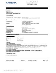
<strong>Commercial</strong> Hot Water or Steam <strong>Boiler</strong>Burner Mounting Plates and Adapter PlatesBECKETT (“CF” SERIES) BURNER ADAPTER PLATEI.D. ‘A’ ‘B’ ‘C’BOILER MODEL PART NO. NO. DIA. DIA. REF.<strong>24</strong>-03 THRU <strong>24</strong>-05 330400 920 4-3/4 10 7-1/16<strong>24</strong>-06 THRU <strong>24</strong>-08 330401 921 6-1/8 10 7-1/16<strong>24</strong>-09 THRU <strong>24</strong>-12 330402 922 6-3/4 10 7-1/16BECKETT (“CG” SERIES) BURNER ADAPTER PLATEI.D. ‘A’ ‘B’ ‘C’BOILER MODEL PART NO. NO. DIA. DIA. REF.<strong>24</strong>-03 THRU <strong>24</strong>-06 330400 920 4-3/4 10 7-1/16<strong>24</strong>-07 THRU <strong>24</strong>-08 330401 921 6-1/8 10 7-1/16<strong>24</strong>-09 THRU <strong>24</strong>-11 330403 923 7-1/4 10 7-1/16<strong>24</strong>-12 330404 9<strong>24</strong> 8-1/8 10 7-1/16Note:1. A burner adapter plate is needed for each boiler.‘B’ DIABOLT CIRCLE‘C’(REF)Control TappingsTAPPING SIZELOCATION (IN.) STEAM BOILER WATER BOILERA 4 Supply SupplyB 4Plug (<strong>24</strong>-03 thru <strong>24</strong>-06)Supply (<strong>24</strong>-07 thru <strong>24</strong>-12)PlugC 3 Blow-Off Valve ReturnD 3 ReturnPlug (<strong>24</strong>-03 thru <strong>24</strong>-11)Return (<strong>24</strong>-12)E 3 Plug Blow-Off / Drain ValveF 3 Plug PlugG 1-1/2 Safety Valve / Surface Skim Tap Relief ValveJ1 1 Plug PlugJ2 1 Float L.W.C.O. PlugK 3/4 Plug Probe L.W.C.O.M 3/4 Operating Pressure Limit Control Operating Temperature Limit ControlN 3/4Hi PressureHi TemperatureLimit Control / Manual Reset Limit Control/Manual ResetP 1/2 Gauge Glass/#67 L.W.C.O. PlugQ 1/2 Steam Gauge (Bush to 1/4”)Temperature/PressureGauge (Bush to 1/4”)S 3/4 Tankless Heater Control Tankless Heater ControlT 3/4 Firing Rate Pressure Control Firing Rate Temperature Control4 8J1AJ2B‘A’ DIAHOLEPTIDENTIFICATION NUMBERSTANDARD BURNERADAPTER PLATE4” STANDARD8” EXTENDEDFRONT VIEWSIDE VIEWSCAST IRON BURNER MOUNTING PLATESNSPJ1QMKJ2G<strong>Series</strong> <strong>24</strong> Minimum PipingRecommendations – Water <strong>Boiler</strong>Impact of System Piping – Many hot water systemsare zoned. Some also use mixing valves to control the watertemperature in the system. These features can cause theflow through the boiler to vary dramatically, depending onthe status of the zones or mixing valves. In addition, thelarge water content of many commercial systems has thepotential to subject the boiler to operation with low returntemperatures for an extended period of time. These factorscan shorten the life of a boiler due to thermal shock or fluegas condensation.<strong>Crown</strong>’s 3 Recommendations – On the followingpages, CROWN provides three basic recommendationsfor near-boiler piping that are intended to maximize thelife expectancy of the boiler by protecting it from flue gascondensation and thermal shock. Each protects the boilerby making sure that both of the following conditions are met:■ The flow through the boiler is high enough toensure a temperature rise of less than 40°FFFRONT VIEWEBACK VIEW■ The return temperature does not fall below 135°Ffor an extended period of time.RTC Return Temperature Control – PipingRecommendation 3 makes use of CROWN’s optionalRTC (Return Temperature Control). This control provides aneconomical and effective way of protecting the boiler fromthermal shock and condensation. It can be incorporated intomost hot water systems with minimal modifications to thesystem design and operation. When this option is used onmultiple <strong>Series</strong> <strong>24</strong>s, one RTC is required for each boiler.The CROWN RTC is also available with an outdoor resetoption. This provides additional energy savings bymodulating system water temperature to match thebuilding load requirements.DC
<strong>Series</strong> <strong>24</strong> Minimum Piping Recommendations – Water <strong>Boiler</strong>1Recommendation 1 is usedwhen the load is constant andnot varied due to mixing ormultiple zones. Use when:1SUPPLYREAR OFBOILERDRAIN VALVE(SEE NOTE 4)SUPPLYREAR OFBOILER■ system return water is notless than 135° F forprolonged periods of time■ system flow does not impactflow through the boilerDRAIN VALVE(SEE NOTE 4)3” x 12” NIPPLEAND BELL REDUCER(SEE NOTE 3)2RETURN<strong>24</strong>-03 THRU <strong>24</strong>-11 (W/20°F DROP)<strong>24</strong>-03 THRU <strong>24</strong>-12 (W/40°F DROP) <strong>24</strong>-12 (W/20°F DROP)23 212ARETURNHEADER2BRETURNBRANCH 2RETURNRecommendation 2 is a primary-secondary piping methodthat maintains a constant flow through the boiler by using asecondary boiler circulator. This arrangement isolates theboiler from flow variations but does not safe-guard againstcold return water temperatures. Use when:■ system return water is not less than 135° Ffor prolonged periods of timeSYSTEM PUMP1 SUPPLYBOILER CIRCULATOR(BY OTHERS - SEE NOTE 5)MAX4DCLOSELYSPACEDTEESBOILER CIRCULATOR(BY OTHERS - SEE NOTE 5)DRAIN VALVE(SEE NOTE 4)SYSTEM PUMPSUPPLY■ system flow does not impact flow through theboiler (i.e. zoning, mixing)DRAIN VALVE(SEE NOTE 4)REAR OFBOILER3” x 12” NIPPLEAND BELL REDUCER(SEE NOTE 4)PIPE SIZING AND NOTES FOR RECOMMENDATIONS 1 AND 2RETURN PIPING SIZE (IN)SUPPLY RETURN RETURNPIPING HEADER BRANCHSIZE (IN) (1) RETURN (2) (2A) (QTY.) SIZE (2B)BOILER 20°F 40°F 20°F 40°F 20°F 20°FMAXMODEL DROP DROP DROP DROP DROP DROP4DSYSTEM PUMP<strong>24</strong>-03 2 1-1/2 2 1-1/2 – –MAX<strong>24</strong>-04 2 1-1/2 2 1-1/2 – CLOSELYSUPPLY4D –SYSTEM PUMPSPACED<strong>24</strong>-05 2 1-1/2 2 1-1/2 – – TEESBOILER CIRCULATOR<strong>24</strong>-06 2-1/2 1-1/2 2-1/21SUPPLY 1-1/2 – –(BY OTHERS - SEE NOTE 5)<strong>24</strong>-07 2-1/2 2 2-1/2 2 – –<strong>24</strong>-08 2-1/2BOILER CIRCULATORDRAIN VALVE(BY 2 OTHERS 2-1/2 - SEE NOTE 5) 2 – –(SEE NOTE 4)<strong>24</strong>-09 3 2 3 2 – –<strong>24</strong>-10 3 2-1/2DRAIN VALVE(SEE3NOTE2-1/<strong>24</strong>)– –REAR OF<strong>24</strong>-11 3 2-1/2 3 2-1/2 – –BOILER3” x 12” NIPPLE<strong>24</strong>-12 4 2-1/2 4 2-1/2 3 (2) 3AND BELL REDUCER2312(SEE NOTE 4)Notes:1. All piping is schedule 40.22. Pipe sizes listed are based on a 20° F or 40°F differential (temperature drop).RETURN2BSelect one to match application.RETURN BRANCH3. When specified return piping is less than 3”, install <strong>24</strong>-03 3” x 12” THRU nipple <strong>24</strong>-11 and (W/20°F appropriate DROP)size bell reducer directly into boiler return tapping as <strong>24</strong>-03 shown. THRU <strong>24</strong>-12 (W/40°F DROP) <strong>24</strong>-12 (W/20°F DROP)4. Drain valve—ball valve preferable, gate valve acceptable alternative(supplied by others).—Minimum valve size per ASME code is 3/4 ” NPT.CLOSELYSPACEDTEESD2RETURNREAR OFBOILER2RETURNRETURN HEADER2ARETU<strong>24</strong>-03 THRU <strong>24</strong>-11 (W/20°F DROP)<strong>24</strong>-03 THRU <strong>24</strong>-12 (W/40°F DROP) <strong>24</strong>
3 DIVERTINGVALVE & ACTUATOR1 SUPPLYTEESD1 SUPPLYBOILER CIRCULATOR(BY OTHERS - SEE NOTE 5)DRAIN VALVE(SEE NOTE 4)SEE NOTE 52 RETURNSEE NOTE 63” x 12” NIPPLEAND BELL REDUCER(SEE NOTE 4)<strong>24</strong>-03 THRU <strong>24</strong>-11 (W/20°F DROP)RETURNRecommendation 3 is used when the return water temperature goes below 135°F for prolonged periods SENSOR (SEE NOTE of 7)time. This is also primary-secondary piping, but includes the addition of a 3-way valve, return water sensor andboiler-mounted RTC Return Temperature Control.3 DIVERTINGVALVE & ACTUATOR1 SUPPLYBOILER CIRCULATOR(BY OTHERS - SEE NOTE 5)DRAIN VALVE(SEE NOTE 4)SYSTEMPUMP MAX4D1 SUPPLYREAR OFBOILER<strong>24</strong>-03 THRU <strong>24</strong>-11 (W/20°F DROP)<strong>24</strong>-03 THRU <strong>24</strong>-12 (W/40°F DROP)PIPE SIZING AND NOTES FOR RECOMMENDATION 3RETURN PIPING SIZE (IN)SUPPLY RETURN RETURN PUMPPIPING HEADER BRANCHSIZE (IN) (1) RETURN (2) (2A) (QTY.) 1 SUPPLYSIZE (2B)3 DIVERTINGBOILER 20°F 40°F 20°F 40°F 20°F 20°FVALVE & ACTUATORMODEL DROP DROP DROP DROP DROP DROP1 SUPPLY<strong>24</strong>-03 2 1-1/2 2 1-1/2 BOILER – CIRCULATOR –<strong>24</strong>-04 2 1-1/2 2 1-1/2(BY OTHERS - SEE NOTE 5)– –<strong>24</strong>-05 2 1-1/2 2 1-1/2 –DRAIN VALVE–(SEE NOTE 4)<strong>24</strong>-06 2-1/2 1-1/2 2-1/2 1-1/2 – –<strong>24</strong>-07 2-1/2 2 2-1/2 2 – –<strong>24</strong>-08 2-1/2 2 2-1/2 2 – –<strong>24</strong>-09 3 2 3 2 –REAR OFBOILER –<strong>24</strong>-10 3 2-1/2 3 2-1/2 – – 2B<strong>24</strong>-11 3 2-1/2 3 2-1/2 – –<strong>24</strong>-12 4 2-1/2 4 2-1/2 3 (2) 3SYSTEMRETURN BRANCHMAX4D<strong>24</strong>-12 (W/20°F DROP)CLOSELYSPACEDTEESDSEE NOTE 52 RETURNSEE NOTE 63” x 12” NIPPLEAND BELL REDUCER(SEE NOTE 4)2RETURNRETURNSENSOR (SEE NOTE 7)Notes: CLOSELYSPACED1. All piping TEES is schedule 40.D<strong>24</strong>-03 THRU <strong>24</strong>-12 (W/40°F DROP)3 DIVERTINGVALVE & ACTUATOR1 SUPPLYBOILER CIRCULATOR(BY OTHERS - SEE NOTE 5)DRAIN VALVE(SEE NOTE 4)REAR OFBOILER1 SUPPLYREAR OFBOILERSYSTEMPUMP2BRETURN BRANCH<strong>24</strong>-12 (W/20°F DROP)CLOSELYSPACEDTEESD2. Pipe sizes listed are based on a 20° F or 40°F differential (temperature drop).Select one to match application.3. When specifiedSEEreturnNOTEpiping5is less than 3”, install 3” x 12” nipple and appropriatesize bell reducer directly into boiler return tapping as shown.2 RETURN4. Drain valve—ball valve preferable, gate valve acceptable alternativeSEE NOTE 6(supplied by others).—Minimum valve size per ASME code is 3/4” NPT.5. Maximum linear feet of pipe from 3-way bypass port to sensor location = 11 feet.Bypass line shall be the same diameter as return A.6. Minimum linear feet 2of pipe from point of mixing (where bypass meets return line)to sensor location RETURN = 4 feet.RETURN HEADER7. Install special 3” x 12” nipple with 1/4” NPT side tapping closest to boiler.RETURN 2AWhere applicable,SENSORuse bell reducer to adapt to recommended return pipe size.(SEE NOTE 7)8. Proper boiler circulator sizing is listed in RTC literature.MAX4D2RETURNSEE NOTE 52 RETURNSEE NOTE 62RETURNRETURN HEADERRETURN 2ASENSOR(SEE NOTE 7)<strong>Series</strong> <strong>24</strong> Minimum Piping Recommendations – Steam <strong>Boiler</strong>‘A’‘A’1 1 ‘A’18” MIN.‘A’1‘B’1 1 18” MIN.RISER1(SEE NOTE 5) (SEE NOTE 5)‘B’‘A’‘A’RISER2(SEE NOTE 5) (SEE NOTE 5)1 1 218” MIN.12‘B’2RISER(SEE NOTE 5)22(SEE NOTE 5) (SEE NOTE 5)<strong>24</strong>” MIN.(SEE NOTE 4) (SEE NOTE 4)(SEE NOTE 5)2222<strong>24</strong>” MIN.(SEE NOTE 4) (SEE NOTE 4)SUPPLY<strong>24</strong>2(SEE NOTE 5)2<strong>24</strong>SEE NOTE 2WATER LINESUPPLY4<strong>24</strong>” MIN.(SEE NOTE 4) (SEE NOTE 4)HEADER22(SEE NOTE 4)4SEE NOTE 22” TO 4”BLOW-OFF/ WATER LINEHEADER(SEE NOTE 3)EQUALIZERDRAIN VALVESUPPLY(SEE NOTE 4)442(SEE 2” NOTE TO 3) 4”BLOW-OFF/(SEE NOTE 3)(SEE NOTE 3)43CLOSE NIPPLEQUALIZERSEE NOTE 2DRAIN VALVE4WATER LINEHEADER(SEE NOTE 3)(SEE NOTE 3)(SEE NOTE 4)33HARTFORD LOOP CLOSE NIPPLE2” TO 4”BLOW-OFF/(SEE NOTE 3) 3<strong>24</strong>-03 THRU <strong>24</strong>-06<strong>24</strong>-07 THRU <strong>24</strong>-11 (REQ’D ON GRAVITYEQUALIZERDRAIN VALVE4REAR OF BOILER(SEE NOTE HARTFORD 3) LOOP(SEE NOTE 3)RETURN SYSTEM) 3<strong>24</strong>-03 3 THRU <strong>24</strong>-06<strong>24</strong>-07 THRU <strong>24</strong>-11 (REQ’D ON GRAVITY CLOSE NIPPLEREAR OF BOILER3RETURN SYSTEM)HARTFORD 3 LOOP DRAIN VALVERETURN<strong>24</strong>-07 THRU <strong>24</strong>-11 (REQ’D ON GRAVITY (WET RETURN)REAR OF BOILERDRAIN VALVERETURN <strong>24</strong>-12 SYSTEM) 3 (WET RETURN)RETURN <strong>24</strong>-12<strong>24</strong>-03 THRU <strong>24</strong>-06RISERPIPING SIZE (IN)SPACING (IN)RISER HEADERBOILER (QTY.) & SUPPLY RETURN EQUALIZERMODEL SIZE (1) (2) (3) (4) ‘A’ ‘B’<strong>24</strong>-03 (1) 3” 3” 1-1/2” 2” – –<strong>24</strong>-04 (1) 4” 4” 2” 2” – –<strong>24</strong>-05 (1) 4” 4” 2” 2” – –<strong>24</strong>-06 (1) 4” 4” 2-1/2” 2-1/2” – –<strong>24</strong>-07 (2) 4” 6” 2-1/2” 2-1/2” 36” –<strong>24</strong>-08 (2) 4” 6” 2-1/2” 2-1/2” 42” –<strong>24</strong>-09 (2) 4” 6” 2-1/2” 2-1/2” 48” –<strong>24</strong>-10 (2) 4” 6” 3” 3” 54” –<strong>24</strong>-11 (2) 4” 6” 3” 3” 60” –<strong>24</strong>-12 (3) 4” 6” 3” 3” 30” 36”Notes:1. All piping is schedule 40.2. To prevent condensate from being trapped in header, do not reduce equalizer elbow at headerconnection.3. Drain/blowoff valve—ball valve preferable, gate valve acceptable alternative (supplied by others).• Mininim valve size per ASME code is 3/4” NPT <strong>24</strong>-03/<strong>24</strong>-05; 1” NPT <strong>24</strong>-06/<strong>24</strong>-10;1-1/4” NPT <strong>24</strong>-11/<strong>24</strong>-12.• Increasing the valve size will improve the blowdown operation• In all cases, piping connection blowoff valve to boiler should be full size to the point of discharge.4. For pumped return systems, see <strong>Series</strong> <strong>24</strong> installation manual.<strong>24</strong>-12DRAIN VALVE(WET RETURN)
<strong>Commercial</strong> Hot Water or Steam <strong>Boiler</strong><strong>Series</strong> <strong>24</strong> SpecificationsBURNER HEATING WATER BOILER WEIGHTNET I=B=R RATING INPUT SURFACE NET PRESSURE CONTENT w/ WATERGROSS (SQ. FT.) FIREBOX IN (GAL.) (LBS.) VENTBOILER HORSE- OUTPUT SQ. FT. MBH MBH OIL GAS VOLUME FIREBOX DIA.MODEL POWER (MBH) STEAM STEAM WATER (GPH) (MBH) STEAM WATER (CU. FT.) (“W.C.”) STEAM WATER STEAM WATER (IN.)<strong>24</strong>-03 10.2 342 1071 257 297 3.05 438 34.2 37.0 3.2 .33 44.5 66.0 1439 1618 7<strong>24</strong>-04 14.1 471 1471 353 410 4.10 594 48.6 54.3 4.8 .38 53.0 75.0 1811 1995 7<strong>24</strong>-05 18.9 634 1983 476 551 5.50 792 63.0 71.5 6.4 .31 61.5 84.0 2184 2372 8<strong>24</strong>-06 23.8 797 <strong>24</strong>92 598 693 6.90 990 77.5 88.8 7.9 .38 70.0 93.0 2557 2749 8<strong>24</strong>-07 28.0 937 2929 703 815 8.10 1174 91.9 106.0 9.5 .36 78.5 102.0 2930 3126 8<strong>24</strong>-08 32.5 1087 3396 815 945 9.40 1358 106.3 123.3 11.0 .35 87.0 111.0 3303 3503 10<strong>24</strong>-09 39.3 1316 4146 995 1148 11.40 1641 120.7 140.5 12.6 .35 95.5 120.0 3676 3880 10<strong>24</strong>-10 45.0 1505 4788 1149 1309 13.00 1867 135.1 157.8 14.2 .40 104.0 129.0 4048 4257 10<strong>24</strong>-11 50.5 1690 5429 1303 1470 14.60 2093 149.5 175.0 15.7 .45 112.5 138.0 4421 4634 12<strong>24</strong>-12 55.3 1852 5983 1436 1610 16.00 2320 164.0 192.3 17.3 .49 121.0 147.0 4794 5011 12Notes:1. Trim suffix S = Steam <strong>Boiler</strong> W = Water <strong>Boiler</strong>Fuel suffix N = Natural Gas O = Oil2. I=B=R net ratings shown are based on piping and pick-up allowances which vary from 1.333 to 1.289 for steam and 1.15 for water. Consult manufacturer for installations having unusual piping and pick-uprequirements, such as intermittent system operation, extensive piping systems, etc. The I=B=R burner capacity in GPH is based on oil having a heat value of 140,000 BTU per gallon.3. Firebox volume does not include added volume of 8” extended burner mounting plate (BMP). If 8” BMP is specified (refer to Figure 1), add 0.7 cu. ft. to volume listed above.4. <strong>Boiler</strong> ratings are based on 12.5% CO2 (oil) and 9.7% CO2 (natural gas), + .10” (inches) water column pressure at boiler flue outlet. Ratings shown above apply at altitudes up to 1000 feet on oil and 2,000feet on gas. For altitudes above those indicated, the ratings should be reduced at the rate of 4% for each 1000 feet above sea level.Maximum Allowable Working Pressure: Steam <strong>Boiler</strong> – 15 PSI, Water <strong>Boiler</strong> – 50 PSIStandard Safety (Relief) Valve Set Pressure: Steam <strong>Boiler</strong> – 15 PSI, Water <strong>Boiler</strong> – 30 PSIBeckett Gas Burners (Natural Gas)Min. Inlet Gas<strong>Boiler</strong> Burner Rate STD. Motor Pressure TrainModel Model Control Voltage H.P. (in W.C.) Size<strong>24</strong>-03 CG10.1S On/Off 120/60/1 1/3 3.2 1”<strong>24</strong>-04 CG10.4S On/Off 120/60/1 1/3 3.6 1”<strong>24</strong>-05 CG10.5S On/Off 120/60/1 1/3 4.3 1-1/4”<strong>24</strong>-06 CG10.6S On/Off 120/60/1 1/3 4.4 1-1/2”<strong>24</strong>-07 CG15.3S Lo/Hi/Lo 120/60/1 1/2 4.0 1-1/2”<strong>24</strong>-08 CG15.4S Lo/Hi/Lo 120/60/1 1/2 4.4 1-1/2”<strong>24</strong>-09 CG25.2S Lo/Hi/Lo 120/60/1 3/4 4.3 1-1/2”<strong>24</strong>-10 CG25.3S Lo/Hi/Lo 120/60/1 3/4 4.9 1-1/2”<strong>24</strong>-11 CG25.4S Lo/Hi/Lo 120/60/1 3/4 4.9 1-1/2”<strong>24</strong>-12 CG50.2S Lo/Hi/Lo 208-<strong>24</strong>0/60/1 2 3.9 1-1/2”Beckett Oil Burners<strong>Boiler</strong> Burner Rate STD. MotorModel Model Control Voltage H.P.<strong>24</strong>-03 CF500 On/Off 120/60/1 1/3<strong>24</strong>-04 CF800 On/Off 120/60/1 1/3<strong>24</strong>-05 CF800 On/Off 120/60/1 1/3<strong>24</strong>-06 CF1400 Lo/Hi/Lo 120/60/1 1/2<strong>24</strong>-07 CF1400 Lo/Hi/Lo 120/60/1 1/2<strong>24</strong>-08 CF1400 Lo/Hi/Lo 120/60/1 1/2<strong>24</strong>-09 CF2300A Lo/Hi/Lo 120/60/1 3/4<strong>24</strong>-10 CF2300A Lo/Hi/Lo 120/60/1 3/4<strong>24</strong>-11 CF2500 Lo/Hi/Lo <strong>24</strong>0/60/1 2<strong>24</strong>-12 CF2500 Lo/Hi/Lo <strong>24</strong>0/60/1 2Minimum gas pressures shown are for standard burners only.See manual for minimum gas pressure when other size gas trains are used.AVAILABLE FROMSince 1949, homeowners have depended on usfor quality, value and service.3633 I Street, P.O. Box 14818Philadelphia, PA 19134Phone: (215) 535-8900 Fax: (215) 535-9736www.crownboiler.comS<strong>24</strong>-12/05 (25M)PN980521