KR 300-2 PA, KR 470-2 PA - KUKA Robotics
KR 300-2 PA, KR 470-2 PA - KUKA Robotics
KR 300-2 PA, KR 470-2 PA - KUKA Robotics
- No tags were found...

Create successful ePaper yourself
Turn your PDF publications into a flip-book with our unique Google optimized e-Paper software.
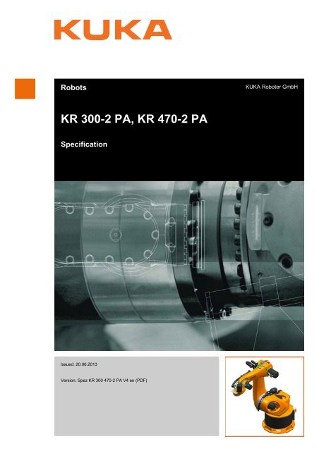
<strong>KR</strong> <strong>300</strong>-2 <strong>PA</strong>, <strong>KR</strong> <strong>470</strong>-2 <strong>PA</strong>© Copyright 2013<strong>KUKA</strong> Roboter GmbHZugspitzstraße 140D-86165 AugsburgGermanyThis documentation or excerpts therefrom may not be reproduced or disclosed to third parties withoutthe express permission of <strong>KUKA</strong> Roboter GmbH.Other functions not described in this documentation may be operable in the controller. The user hasno claims to these functions, however, in the case of a replacement or service work.We have checked the content of this documentation for conformity with the hardware and softwaredescribed. Nevertheless, discrepancies cannot be precluded, for which reason we are not able toguarantee total conformity. The information in this documentation is checked on a regular basis, however,and necessary corrections will be incorporated in the subsequent edition.Subject to technical alterations without an effect on the function.Translation of the original documentationKIM-PS5-DOCPublication:Pub Spez <strong>KR</strong> <strong>300</strong> <strong>470</strong>-2 <strong>PA</strong> (PDF) enBook structure: Spez <strong>KR</strong> <strong>300</strong> <strong>470</strong>-2 <strong>PA</strong> V3.1Version:Spez <strong>KR</strong> <strong>300</strong> <strong>470</strong>-2 <strong>PA</strong> V4 en (PDF)2 / 73 Issued: 20.06.2013 Version: Spez <strong>KR</strong> <strong>300</strong> <strong>470</strong>-2 <strong>PA</strong> V4 en (PDF)
ContentsContents1 Introduction .................................................................................................. 51.1 Industrial robot documentation ................................................................................... 51.2 Representation of warnings and notes ...................................................................... 52 Purpose ........................................................................................................ 72.1 Target group .............................................................................................................. 72.2 Intended use .............................................................................................................. 73 Product description ..................................................................................... 93.1 Overview of the robot system .................................................................................... 93.2 Description of the robot .............................................................................................. 94 Technical data .............................................................................................. 134.1 Basic data .................................................................................................................. 134.2 Axis data .................................................................................................................... 144.3 Payloads .................................................................................................................... 164.4 Foundation data ......................................................................................................... 204.5 Transport dimensions ................................................................................................ 214.6 Plates and labels ........................................................................................................ 224.7 Stopping distances and times .................................................................................... 234.7.1 General information .............................................................................................. 234.7.2 Terms used ........................................................................................................... 234.7.3 Stopping distance and stopping times for <strong>KR</strong> <strong>300</strong> <strong>PA</strong> .......................................... 244.7.3.1 Stopping distances and stopping times for STOP 0, axis 1 to axis 3 .............. 244.7.3.2 Stopping distances and stopping times for STOP 1, axis 1 ............................. 254.7.3.3 Stopping distances and stopping times for STOP 1, axis 2 ............................. 274.7.3.4 Stopping distances and stopping times for STOP 1, axis 3 ............................. 294.7.4 Stopping distance and stopping times for <strong>KR</strong> <strong>470</strong> <strong>PA</strong> .......................................... 294.7.4.1 Stopping distances and stopping times for STOP 0, axis 1 to axis 3 .............. 294.7.4.2 Stopping distances and stopping times for STOP 1, axis 1 ............................. 304.7.4.3 Stopping distances and stopping times for STOP 1, axis 3 ............................. 324.7.4.4 Stopping distances and stopping times for STOP 1, axis 2 ............................. 335 Safety ............................................................................................................ 355.1 General ...................................................................................................................... 355.1.1 Liability .................................................................................................................. 355.1.2 Intended use of the industrial robot ...................................................................... 365.1.3 EC declaration of conformity and declaration of incorporation ............................. 365.1.4 Terms used ........................................................................................................... 375.2 Personnel ................................................................................................................... 385.3 Workspace, safety zone and danger zone ................................................................. 395.4 Overview of protective equipment .............................................................................. 405.4.1 Mechanical end stops ........................................................................................... 405.4.2 Mechanical axis range limitation (optional) ........................................................... 405.4.3 Axis range monitoring (optional) ........................................................................... 415.4.4 Options for moving the manipulator without drive energy ..................................... 415.4.5 Labeling on the industrial robot ............................................................................. 425.5 Safety measures ........................................................................................................ 42Issued: 20.06.2013 Version: Spez <strong>KR</strong> <strong>300</strong> <strong>470</strong>-2 <strong>PA</strong> V4 en (PDF)3 / 73
<strong>KR</strong> <strong>300</strong>-2 <strong>PA</strong>, <strong>KR</strong> <strong>470</strong>-2 <strong>PA</strong>5.5.1 General safety measures ..................................................................................... 425.5.2 Transportation ...................................................................................................... 435.5.3 Start-up and recommissioning .............................................................................. 445.5.4 Manual mode ........................................................................................................ 455.5.5 Automatic mode ................................................................................................... 455.5.6 Maintenance and repair ........................................................................................ 465.5.7 Decommissioning, storage and disposal .............................................................. 475.6 Applied norms and regulations .................................................................................. 476 Planning ........................................................................................................ 496.1 Mounting base for 175 mm concrete thickness ......................................................... 496.2 Mounting base for 200 mm concrete thickness ......................................................... 516.3 Machine frame mounting ........................................................................................... 536.4 Connecting cables and interfaces ............................................................................. 547 Transportation ............................................................................................. 577.1 Transporting the robot ............................................................................................... 578 Options ......................................................................................................... 618.1 Release device (optional) .......................................................................................... 619 <strong>KUKA</strong> Service ............................................................................................... 639.1 Requesting support ................................................................................................... 639.2 <strong>KUKA</strong> Customer Support ........................................................................................... 63Index ............................................................................................................. 714 / 73 Issued: 20.06.2013 Version: Spez <strong>KR</strong> <strong>300</strong> <strong>470</strong>-2 <strong>PA</strong> V4 en (PDF)
1 Introduction1 Introduction1.1 Industrial robot documentationThe industrial robot documentation consists of the following parts:• Documentation for the manipulator• Documentation for the robot controller• Operating and programming instructions for the <strong>KUKA</strong> System Software• Documentation relating to options and accessories• Parts catalog on storage mediumEach of these sets of instructions is a separate document.1.2 Representation of warnings and notesSafetyThese warnings are relevant to safety and must be observed.are taken.These warnings mean that it is certain or highly probablethat death or severe injuries will occur, if no precautionsThese warnings mean that death or severe injuries mayoccur, if no precautions are taken.These warnings mean that minor injuries may occur, ifno precautions are taken.These warnings mean that damage to property may occur,if no precautions are taken.These warnings contain references to safety-relevant information orgeneral safety measures.These warnings do not refer to individual hazards or individual precautionarymeasures.This warning draws attention to procedures which serve to prevent or remedyemergencies or malfunctions:Procedures marked with this warning must be followedexactly.NotesThese hints serve to make your work easier or contain references to furtherinformation.Tip to make your work easier or reference to further information.Issued: 20.06.2013 Version: Spez <strong>KR</strong> <strong>300</strong> <strong>470</strong>-2 <strong>PA</strong> V4 en (PDF)5 / 73
<strong>KR</strong> <strong>300</strong>-2 <strong>PA</strong>, <strong>KR</strong> <strong>470</strong>-2 <strong>PA</strong>6 / 73 Issued: 20.06.2013 Version: Spez <strong>KR</strong> <strong>300</strong> <strong>470</strong>-2 <strong>PA</strong> V4 en (PDF)
2 Purpose2 Purpose2.1 Target groupThis documentation is aimed at users with the following knowledge and skills:• Advanced knowledge of mechanical engineering• Advanced knowledge of electrical and electronic systems• Knowledge of the robot controller systemFor optimal use of our products, we recommend that our customerstake part in a course of training at <strong>KUKA</strong> College. Information aboutthe training program can be found at www.kuka.com or can be obtaineddirectly from our subsidiaries.2.2 Intended useUseMisuseThe industrial robot is intended for handling tools and fixtures, or for processingor transferring components or products. Use is only permitted under thespecified environmental conditions.Any use or application deviating from the intended use is deemed to be impermissiblemisuse. This includes e.g.:• Transportation of persons and animals• Use as a climbing aid• Operation outside the permissible operating parameters• Use in potentially explosive environments• Use in underground miningChanging the structure of the manipulator, e.g. by drillingholes, etc., can result in damage to the components. Thisis considered improper use and leads to loss of guarantee and liability entitlements.The robot system is an integral part of a complete system and mayonly be operated in a CE-compliant system.Issued: 20.06.2013 Version: Spez <strong>KR</strong> <strong>300</strong> <strong>470</strong>-2 <strong>PA</strong> V4 en (PDF)7 / 73
<strong>KR</strong> <strong>300</strong>-2 <strong>PA</strong>, <strong>KR</strong> <strong>470</strong>-2 <strong>PA</strong>8 / 73 Issued: 20.06.2013 Version: Spez <strong>KR</strong> <strong>300</strong> <strong>470</strong>-2 <strong>PA</strong> V4 en (PDF)
3 Product description3 Product description3.1 Overview of the robot systemThe industrial robot consists of the following components:• Manipulator• Robot controller• Teach pendant• Connecting cables• Software• Options, accessoriesFig. 3-1: Robot system <strong>KR</strong> <strong>300</strong>, <strong>470</strong>-2 <strong>PA</strong>1 Robot 3 <strong>KR</strong> C4 robot controller2 Connecting cables 4 Teach pendant KCP (<strong>KUKA</strong>smart<strong>PA</strong>D)3.2 Description of the robotOverviewThis robot is designed as a 5-axis jointed-arm kinematic system. The structuralcomponents of the robots are made of light alloy and iron castings. The axesare driven by AC servomotors. A hydropneumatic counterbalancing system isused to equalize the load moment about axis 2.The robot consists of the following principal components (>>> Fig. 3-2 ):• Wrist• Arm• Link arm• Rotating column• Base frame• Counterbalancing system• Electrical installationsIssued: 20.06.2013 Version: Spez <strong>KR</strong> <strong>300</strong> <strong>470</strong>-2 <strong>PA</strong> V4 en (PDF)9 / 73
<strong>KR</strong> <strong>300</strong>-2 <strong>PA</strong>, <strong>KR</strong> <strong>470</strong>-2 <strong>PA</strong>Fig. 3-2: <strong>KR</strong> <strong>300</strong> <strong>470</strong>-2 <strong>PA</strong>: main assemblies1 Wrist 5 Electrical installations2 Arm 6 Base frame3 Link arm 7 Rotating column4 Counterbalancing systemWristArmThe robot variants <strong>KR</strong> <strong>300</strong> <strong>PA</strong> and <strong>KR</strong> <strong>470</strong> <strong>PA</strong> robots are equipped with a twoaxiswrist for rated payloads of <strong>300</strong> kg and <strong>470</strong> kg, respectively. The wrist isfastened to the arm via a gear unit and motor and is driven by these. The maincomponents of the wrist are the swing frame, axis 6 motor and the correspondinggear unit. The mounting flange embodies the output side of axis 6. The motorunit consists of a brushless AC servomotor with a permanent-magnetsingle-disk brake and hollow-shaft resolver, both integrated. The permanentmagnetsingle-disk brake performs a holding function when the servomotor isat rest and contributes to the braking of axis 6 in the event of short-circuit braking(e.g. if one or more of the enabling switches is released while in Testmode). Short-circuit braking must not be used to stop the robot under normalcircumstances. End effectors can be attached to the mounting flange of axis6. The wrist is designed as a hollow-shaft wrist and features a through-holewith a diameter of 60 mm.The assembly also has a gauge mount with a gauge cartridge, through whichthe mechanical zero of the axis can be determined by means of a dial gaugeor an electronic probe (accessory) and transferred to the controller.The arm is the transmission element between the wrist and the link arm. Theswing frame of the wrist is mounted on the arm via gear unit A5. This motor/gear combination embodies axis 5, which cannot be freely controlled duringoperation. The arm is driven by an AC servomotor via a gear unit that is installedbetween the arm and the link arm. This gear unit is also the bearing forthe arm. The maximum permissible swivel angle is mechanically limited by astop for each direction, plus and minus. The buffers are attached to the arm.The corresponding stops are situated on the link arm.10 / 73 Issued: 20.06.2013 Version: Spez <strong>KR</strong> <strong>300</strong> <strong>470</strong>-2 <strong>PA</strong> V4 en (PDF)
3 Product descriptionLink armRotating columnBase frameCounterbalancingsystemElectrical installationsOptionsThe link arm is the assembly located between the arm and the rotating column.It is mounted on one side of the rotating column via the gear unit of axis 2 andis driven by an AC servomotor. During motion about axis 2, the link arm movesabout the stationary rotating column. The cable harness of the electrical installationsis routed inside the link arm and is mounted in hinged clamps.The rotating column houses the motors of axes 1 and 2. The rotational motionof axis 1 is performed by the rotating column. It is screwed to the base framevia the gear unit of axis 1. The AC servomotor for driving axis 1 is mountedinside the rotating column. The counterbearing for the counterbalancing systemis integrated into the rear of the rotating column housing. The fork slotsare also screwed to the rotating column if the robot is transported using a forklift truck.The base frame is the base of the robot. It is screwed to the mounting base.The interfaces for the electrical installations and the energy supply systems(accessory) are housed in the base frame. The base frame and rotating columnare connected via the gear unit of axis 1. The flexible tube for the electricalinstallations and the energy supply system is accommodated in the baseframe.The counterbalancing system is installed between the rotating column and thelink arm and serves to minimize the moments generated about axis 2 when therobot is in motion and at rest. A closed, hydropneumatic system is used. Thesystem consists of two accumulators, a hydraulic cylinder with associated hoses,a pressure gauge and an accumulator safety valve as a safety element toprotect against overload. The accumulators correspond to category II, fluidgroup 2, of the Pressure Equipment Directive.The electrical installations are described in Chapter .The robot can be fitted and operated with various options, such as energy supplysystems for axes 1 to 3, energy supply systems for axes 3 to 6, or workingrange limitation systems. The options are described in separate documentation.Issued: 20.06.2013 Version: Spez <strong>KR</strong> <strong>300</strong> <strong>470</strong>-2 <strong>PA</strong> V4 en (PDF)11 / 73
<strong>KR</strong> <strong>300</strong>-2 <strong>PA</strong>, <strong>KR</strong> <strong>470</strong>-2 <strong>PA</strong>12 / 73 Issued: 20.06.2013 Version: Spez <strong>KR</strong> <strong>300</strong> <strong>470</strong>-2 <strong>PA</strong> V4 en (PDF)
4 Technical data4 Technical data4.1 Basic dataBasic dataAmbient temperatureType<strong>KR</strong> <strong>300</strong>-2 <strong>PA</strong><strong>KR</strong> <strong>470</strong>-2 <strong>PA</strong>Number of axes 5Volume of working 73.5 m³envelopePose repeatability(ISO 9283)Work envelope referencepointReachWeight of robotWeight of transportframePrincipal dynamicloadsProtection classificationof the robotProtection classificationof the wristSound levelMounting positionSurface finish, paintworkOperationStorage andtransportation<strong>KR</strong> <strong>300</strong>-2 <strong>PA</strong> ±0.08 mm<strong>KR</strong> <strong>470</strong>-2 <strong>PA</strong> ±0.08 mmIntersection of axis 6 with the mounting flangeface3,150 mm2,150 kg212 kgSee “Loads acting on the mounting base”IP65ready for operation, with connecting cablesplugged in (according to EN 60529)IP65< 72 dB (A) outside the working envelopeFloorBase (stationary) and counterbalancing system:RAL 9005; moving parts: <strong>KUKA</strong> orange 2567278 K to 328 K (+5 °C to +55 °C)233 K to 333 K (-40 °C to +60 °C)Start-up278 K to 288 K (+5 °C to +15 °C)At these temperatures the robot may have to bewarmed up before normal operation. Other temperaturelimits available on request.Ambient conditions DIN EN 60721-3-3,Class 3K3The maintenance intervals and the specified service life are based on typicalgear unit temperatures and axis motions. If special functions or applicationsresult in atypical gear unit temperatures or axis motions, this can lead to increasedwear. In this case, the maintenance intervals or service life may beshortened. If you have any questions, please contact <strong>KUKA</strong> Customer Support.ConnectingcablesCable designation Connector designationInterface with robotMotor cable X20.1 - X30.1 Harting connectorsat both endsMotor cable X20.4 - X30.4 Harting connectorsat both endsIssued: 20.06.2013 Version: Spez <strong>KR</strong> <strong>300</strong> <strong>470</strong>-2 <strong>PA</strong> V4 en (PDF)13 / 73
<strong>KR</strong> <strong>300</strong>-2 <strong>PA</strong>, <strong>KR</strong> <strong>470</strong>-2 <strong>PA</strong>Cable designationControl cable X21 - X31 HAN 3A EMCat both endsGround conductor /equipotential bonding16 mm 2(can be ordered as anoption)Connector designationInterface with robotM8 ring cable lugat both endsCable lengthsStandardMinimum bending radius7 m, 15 m, 25 m, 35 m, 50 m10x DFor detailed specifications of the connecting cables, see (>>> 6.4 "Connectingcables and interfaces" Page 54).4.2 Axis dataAxis dataThe following data are valid for the robot <strong>KR</strong> <strong>300</strong>-2 <strong>PA</strong>.AxisRange of motion, softwarelimitedSpeed withrated payload1 +/-185° 97.5 °/s2 +20° to -130° 91.0 °/s3 +155° to -0°* 89.0 °/s5 Axis not actively selectable6 +/-350° 177.0 °/sThe following data are valid for the robot <strong>KR</strong> <strong>470</strong>-2 <strong>PA</strong>.AxisRange of motion, softwarelimitedSpeed withrated payload1 +/-185° 84.0 °/s2 +20° to -130° 78.0 °/s3 +155° to -0°* 73.0 °/s5 Axis not actively selectable6 +/-350° 177.0 °/s* Maximum value, referred to the link arm, depending on the position of axis 2The direction of motion and the arrangement of the individual axes may be notedfrom the diagram (>>> Fig. 4-1 ).14 / 73 Issued: 20.06.2013 Version: Spez <strong>KR</strong> <strong>300</strong> <strong>470</strong>-2 <strong>PA</strong> V4 en (PDF)
4 Technical dataFig. 4-1: Direction of rotation of robot axesWorkingenvelopeThe diagram (>>> Fig. 4-2 ) shows the shape and size of the working envelope.The reference point for the working envelope is the intersection of axis 6 withthe mounting flange face.Issued: 20.06.2013 Version: Spez <strong>KR</strong> <strong>300</strong> <strong>470</strong>-2 <strong>PA</strong> V4 en (PDF)15 / 73
<strong>KR</strong> <strong>300</strong>-2 <strong>PA</strong>, <strong>KR</strong> <strong>470</strong>-2 <strong>PA</strong>Fig. 4-2: Working envelope: <strong>KR</strong> <strong>300</strong> <strong>470</strong> <strong>PA</strong>4.3 PayloadsPayloadsRobot <strong>KR</strong> <strong>300</strong>-2 <strong>PA</strong> <strong>KR</strong> <strong>470</strong>-2 <strong>PA</strong>WristHollow-shaft Hollow-shaftwristwrist16 / 73 Issued: 20.06.2013 Version: Spez <strong>KR</strong> <strong>300</strong> <strong>470</strong>-2 <strong>PA</strong> V4 en (PDF)
4 Technical dataRated payload <strong>300</strong> kg <strong>470</strong> kgDistance of the load center of gravity<strong>300</strong> mm <strong>300</strong> mmL zDistance of the load center of gravityL xy100 mm 100 mmPermissible moment of inertia 150 kgm 2 235 kgm 2Max. total load 350 kg 520 kgSupplementary load, arm 50 kg 50 kgSupplementary load, link arm 0 kg 0 kgSupplementary load, rotating column0 kg 0 kgLoad center ofgravity PFor all payloads, the load center of gravity refers to the distance from the faceof the mounting flange on axis 6. Refer to the payload diagram for the nominaldistance.Payload diagramFig. 4-3: Payload diagram for <strong>KR</strong> <strong>300</strong>-2 <strong>PA</strong>Issued: 20.06.2013 Version: Spez <strong>KR</strong> <strong>300</strong> <strong>470</strong>-2 <strong>PA</strong> V4 en (PDF)17 / 73
<strong>KR</strong> <strong>300</strong>-2 <strong>PA</strong>, <strong>KR</strong> <strong>470</strong>-2 <strong>PA</strong>This loading curve corresponds to the maximum load capacity.Both values (payload and mass moment of inertia)must be checked in all cases. Exceeding this capacity will reduce theservice life of the robot and overload the motors and the gears; in any suchcase the <strong>KUKA</strong> Roboter GmbH must be consulted beforehand.The values determined here are necessary for planning the robot application.For commissioning the robot, additional input data are required in accordancewith operating and programming instructions of the <strong>KUKA</strong> SystemSoftware.The mass inertia must be verified using <strong>KUKA</strong>.Load. It is imperative for theload data to be entered in the robot controller!Fig. 4-4: Payload diagram for <strong>KR</strong> <strong>470</strong>-2 <strong>PA</strong>Mounting flangeMounting flangesimilar to DIN/ISO 9409-1-A160*Screw grade 10.9Screw sizeM12Grip length1.5 x nominal diameterDepth of engagementmin. 15 mm, max. 19.5 mmLocating element10 H7Through-hole forenergy supply systemø 60 mm*The inner locating diameter is ø 125 H7 . This deviates from the standard.18 / 73 Issued: 20.06.2013 Version: Spez <strong>KR</strong> <strong>300</strong> <strong>470</strong>-2 <strong>PA</strong> V4 en (PDF)
4 Technical dataThe mounting flange is depicted (>>> Fig. 4-5 ) with axis 6 in the zero position.The symbol X m indicates the position of the locating element (bushing) inthe zero position.Fig. 4-5: Mounting flange1 Fitting length2 Disruptive contour of screw headsSupplementaryloadThe robot can carry supplementary loads on the arm. When mounting the supplementaryloads, be careful to observe the maximum permissible total load.The dimensions and positions of the installation options can be seen in the diagram.All other threads and holes on the robot are not suitable for attachingadditional loads .Issued: 20.06.2013 Version: Spez <strong>KR</strong> <strong>300</strong> <strong>470</strong>-2 <strong>PA</strong> V4 en (PDF)19 / 73
<strong>KR</strong> <strong>300</strong>-2 <strong>PA</strong>, <strong>KR</strong> <strong>470</strong>-2 <strong>PA</strong>Fig. 4-6: Supplementary load on arm1 Axis 3 3 Interference contour on right2 Fastening thread4.4 Foundation dataFoundation loadsThe specified forces and moments already include the payload and the inertiaforce (weight) of the robot.Fig. 4-7: Loads acting on the foundationType of loadF v = vertical forceF h = horizontal forceM k = tilting momentM r = torqueForce/torque/massF vmax = 40,500 NF hmax = 23,500 NM kmax = 84,500 NmM rmax = 45,500 Nm20 / 73 Issued: 20.06.2013 Version: Spez <strong>KR</strong> <strong>300</strong> <strong>470</strong>-2 <strong>PA</strong> V4 en (PDF)
4 Technical dataType of loadTotal mass for foundation loadRobotTotal mass for foundation loadForce/torque/massfor <strong>KR</strong> <strong>300</strong> <strong>PA</strong>: 2,290 kgfor <strong>KR</strong> <strong>470</strong>: 2,410 kg1,940 kgfor <strong>KR</strong> <strong>300</strong> <strong>PA</strong>: 350 kgfor <strong>KR</strong> <strong>470</strong> <strong>PA</strong>: 520 kgThe supplementary loads are not taken into consideration in the calculationof the foundation load. These supplementary loads must betaken into consideration for F v .Grade of concretefor foundationsWhen producing foundations from concrete, observe the load-bearing capacityof the ground and the country-specific construction regulations. There mustbe no layers of insulation or screed between the bedplates and the concretefoundation. The quality of the concrete must meet the requirements of the followingstandard:• C20/25 according to DIN EN 206-1:2001/DIN 1045-2:20084.5 Transport dimensionsThe transport dimensions (>>> Fig. 4-8 ) for the robot can be noted from thefollowing diagram. The position of the center of gravity and the weight vary accordingto the specific configuration. The specified dimensions refer to the robotwithout equipment. The following diagram shows the dimensions of therobot when it stands on the floor without wooden transport blocks.Fig. 4-8: Transport dimensions1 RobotIssued: 20.06.2013 Version: Spez <strong>KR</strong> <strong>300</strong> <strong>470</strong>-2 <strong>PA</strong> V4 en (PDF)21 / 73
<strong>KR</strong> <strong>300</strong>-2 <strong>PA</strong>, <strong>KR</strong> <strong>470</strong>-2 <strong>PA</strong>2 Center of gravity3 Fork slots4.6 Plates and labelsPlates and labelsThe following plates and labels are attached to the robot. They must not be removedor rendered illegible. Illegible plates and labels must be replaced.Fig. 4-9: Plates and labels22 / 73 Issued: 20.06.2013 Version: Spez <strong>KR</strong> <strong>300</strong> <strong>470</strong>-2 <strong>PA</strong> V4 en (PDF)
4 Technical data4.7 Stopping distances and times4.7.1 General informationInformation concerning the data:• The stopping distance is the angle traveled by the robot from the momentthe stop signal is triggered until the robot comes to a complete standstill.• The stopping time is the time that elapses from the moment the stop signalis triggered until the robot comes to a complete standstill.• The data are given for the main axes A1, A2 and A3. The main axes arethe axes with the greatest deflection.• Superposed axis motions can result in longer stopping distances.• Stopping distances and stopping times in accordance with DIN EN ISO10218-1, Annex B.• Stop categories:• Stop category 0 » STOP 0• Stop category 1 » STOP 1according to IEC 60204-1• The values specified for Stop 0 are guide values determined by means oftests and simulation. They are average values which conform to the requirementsof DIN EN ISO 10218-1. The actual stopping distances andstopping times may differ due to internal and external influences on thebraking torque. It is therefore advisable to determine the exact stoppingdistances and stopping times where necessary under the real conditionsof the actual robot application.• Measuring techniqueThe stopping distances were measured using the robot-internal measuringtechnique.• The wear on the brakes varies depending on the operating mode, robotapplication and the number of STOP 0 triggered. It is therefore advisableto check the stopping distance at least once a year.4.7.2 Terms usedTermmPhiPOVExtensionKCPDescriptionMass of the rated load and the supplementary load onthe arm.Angle of rotation (°) about the corresponding axis. Thisvalue can be entered in the controller via the KCP andis displayed on the KCP.Program override (%) = velocity of the robot motion.This value can be entered in the controller via the KCPand is displayed on the KCP.Distance (l in %) (>>> Fig. 4-10 ) between axis 1 andthe intersection of axes 4 and 5. With parallelogramrobots, the distance between axis 1 and the intersectionof axis 6 and the mounting flange.The KCP teach pendant has all the operator controland display functions required for operating and programmingthe robot system.Issued: 20.06.2013 Version: Spez <strong>KR</strong> <strong>300</strong> <strong>470</strong>-2 <strong>PA</strong> V4 en (PDF)23 / 73
<strong>KR</strong> <strong>300</strong>-2 <strong>PA</strong>, <strong>KR</strong> <strong>470</strong>-2 <strong>PA</strong>Fig. 4-10: Extension4.7.3 Stopping distance and stopping times for <strong>KR</strong> <strong>300</strong> <strong>PA</strong>4.7.3.1 Stopping distances and stopping times for STOP 0, axis 1 to axis 3The table shows the stopping distances and stopping times after a STOP 0(category 0 stop) is triggered. The values refer to the following configuration:• Extension l = 100%• Program override POV = 100%• Mass m = maximum load (rated load + supplementary load on arm)Axis 1Axis 2Axis 3Stopping distance (°)Stopping time (s)No data are currently available for STOP 0 for axes 1-3.24 / 73 Issued: 20.06.2013 Version: Spez <strong>KR</strong> <strong>300</strong> <strong>470</strong>-2 <strong>PA</strong> V4 en (PDF)
4 Technical data4.7.3.2 Stopping distances and stopping times for STOP 1, axis 1Fig. 4-11: Stopping distances for STOP 1, axis 1Issued: 20.06.2013 Version: Spez <strong>KR</strong> <strong>300</strong> <strong>470</strong>-2 <strong>PA</strong> V4 en (PDF)25 / 73
<strong>KR</strong> <strong>300</strong>-2 <strong>PA</strong>, <strong>KR</strong> <strong>470</strong>-2 <strong>PA</strong>Fig. 4-12: Stopping times for STOP 1, axis 126 / 73 Issued: 20.06.2013 Version: Spez <strong>KR</strong> <strong>300</strong> <strong>470</strong>-2 <strong>PA</strong> V4 en (PDF)
4 Technical data4.7.3.3 Stopping distances and stopping times for STOP 1, axis 2Fig. 4-13: Stopping distances for STOP 1, axis 2Issued: 20.06.2013 Version: Spez <strong>KR</strong> <strong>300</strong> <strong>470</strong>-2 <strong>PA</strong> V4 en (PDF)27 / 73
<strong>KR</strong> <strong>300</strong>-2 <strong>PA</strong>, <strong>KR</strong> <strong>470</strong>-2 <strong>PA</strong>Fig. 4-14: Stopping times for STOP 1, axis 228 / 73 Issued: 20.06.2013 Version: Spez <strong>KR</strong> <strong>300</strong> <strong>470</strong>-2 <strong>PA</strong> V4 en (PDF)
4 Technical data4.7.3.4 Stopping distances and stopping times for STOP 1, axis 3Fig. 4-15: Stopping distances for STOP 1, axis 3Fig. 4-16: Stopping times for STOP 1, axis 34.7.4 Stopping distance and stopping times for <strong>KR</strong> <strong>470</strong> <strong>PA</strong>4.7.4.1 Stopping distances and stopping times for STOP 0, axis 1 to axis 3The table shows the stopping distances and stopping times after a STOP 0(category 0 stop) is triggered. The values refer to the following configuration:• Extension l = 100%• Program override POV = 100%• Mass m = maximum load (rated load + supplementary load on arm)Axis 1Axis 2Axis 3Stopping distance (°)Stopping time (s)No data are currently available for STOP 0 for axes 1-3.Issued: 20.06.2013 Version: Spez <strong>KR</strong> <strong>300</strong> <strong>470</strong>-2 <strong>PA</strong> V4 en (PDF)29 / 73
<strong>KR</strong> <strong>300</strong>-2 <strong>PA</strong>, <strong>KR</strong> <strong>470</strong>-2 <strong>PA</strong>4.7.4.2 Stopping distances and stopping times for STOP 1, axis 1Fig. 4-17: Stopping distances for STOP 1, axis 130 / 73 Issued: 20.06.2013 Version: Spez <strong>KR</strong> <strong>300</strong> <strong>470</strong>-2 <strong>PA</strong> V4 en (PDF)
4 Technical dataFig. 4-18: Stopping times for STOP 1, axis 1Issued: 20.06.2013 Version: Spez <strong>KR</strong> <strong>300</strong> <strong>470</strong>-2 <strong>PA</strong> V4 en (PDF)31 / 73
<strong>KR</strong> <strong>300</strong>-2 <strong>PA</strong>, <strong>KR</strong> <strong>470</strong>-2 <strong>PA</strong>4.7.4.3 Stopping distances and stopping times for STOP 1, axis 3Fig. 4-19: Stopping distances for STOP 1, axis 3Fig. 4-20: Stopping times for STOP 1, axis 332 / 73 Issued: 20.06.2013 Version: Spez <strong>KR</strong> <strong>300</strong> <strong>470</strong>-2 <strong>PA</strong> V4 en (PDF)
4 Technical data4.7.4.4 Stopping distances and stopping times for STOP 1, axis 2Fig. 4-21: Stopping distances for STOP 1, axis 2Issued: 20.06.2013 Version: Spez <strong>KR</strong> <strong>300</strong> <strong>470</strong>-2 <strong>PA</strong> V4 en (PDF)33 / 73
<strong>KR</strong> <strong>300</strong>-2 <strong>PA</strong>, <strong>KR</strong> <strong>470</strong>-2 <strong>PA</strong>Fig. 4-22: Stopping times for STOP 1, axis 234 / 73 Issued: 20.06.2013 Version: Spez <strong>KR</strong> <strong>300</strong> <strong>470</strong>-2 <strong>PA</strong> V4 en (PDF)
5 Safety5 Safety5.1 General•This “Safety” chapter refers to a mechanical component of an industrialrobot.•If the mechanical component is used together with a <strong>KUKA</strong> robotcontroller, the “Safety” chapter of the operating instructions or assemblyinstructions of the robot controller must be used!This contains all the information provided in this “Safety” chapter. It alsocontains additional safety information relating to the robot controllerwhich must be observed.• Where this “Safety” chapter uses the term “industrial robot”, this also refersto the individual mechanical component if applicable.5.1.1 LiabilityThe device described in this document is either an industrial robot or a componentthereof.Components of the industrial robot:• Manipulator• Robot controller• Teach pendant• Connecting cables• External axes (optional)e.g. linear unit, turn-tilt table, positioner• Software• Options, accessoriesThe industrial robot is built using state-of-the-art technology and in accordancewith the recognized safety rules. Nevertheless, misuse of the industrialrobot may constitute a risk to life and limb or cause damage to the industrialrobot and to other material property.The industrial robot may only be used in perfect technical condition in accordancewith its designated use and only by safety-conscious persons who arefully aware of the risks involved in its operation. Use of the industrial robot issubject to compliance with this document and with the declaration of incorporationsupplied together with the industrial robot. Any functional disorders affectingsafety must be rectified immediately.Safety informationSafety information cannot be held against <strong>KUKA</strong> Roboter GmbH. Even if allsafety instructions are followed, this is not a guarantee that the industrial robotwill not cause personal injuries or material damage.No modifications may be carried out to the industrial robot without the authorizationof <strong>KUKA</strong> Roboter GmbH. Additional components (tools, software,etc.), not supplied by <strong>KUKA</strong> Roboter GmbH, may be integrated into the industrialrobot. The user is liable for any damage these components may cause tothe industrial robot or to other material property.In addition to the Safety chapter, this document contains further safety instructions.These must also be observed.Issued: 20.06.2013 Version: Spez <strong>KR</strong> <strong>300</strong> <strong>470</strong>-2 <strong>PA</strong> V4 en (PDF)35 / 73
<strong>KR</strong> <strong>300</strong>-2 <strong>PA</strong>, <strong>KR</strong> <strong>470</strong>-2 <strong>PA</strong>5.1.2 Intended use of the industrial robotThe industrial robot is intended exclusively for the use designated in the “Purpose”chapter of the operating instructions or assembly instructions.Further information is contained in the “Purpose” chapter of the operatinginstructions or assembly instructions of the industrial robot.Using the industrial robot for any other or additional purpose is considered impermissiblemisuse. The manufacturer cannot be held liable for any damageresulting from such use. The risk lies entirely with the user.Operating the industrial robot and its options within the limits of its intendeduse also involves observance of the operating and assembly instructions forthe individual components, with particular reference to the maintenance specifications.MisuseAny use or application deviating from the intended use is deemed to be impermissiblemisuse. This includes e.g.:• Transportation of persons and animals• Use as a climbing aid• Operation outside the permissible operating parameters• Use in potentially explosive environments• Operation without additional safeguards• Outdoor operation• Underground operation5.1.3 EC declaration of conformity and declaration of incorporationThis industrial robot constitutes partly completed machinery as defined by theEC Machinery Directive. The industrial robot may only be put into operation ifthe following preconditions are met:• The industrial robot is integrated into a complete system.Or: The industrial robot, together with other machinery, constitutes a completesystem.Or: All safety functions and safeguards required for operation in the completemachine as defined by the EC Machinery Directive have been addedto the industrial robot.• The complete system complies with the EC Machinery Directive. This hasbeen confirmed by means of an assessment of conformity.Declaration ofconformityDeclaration ofincorporationThe system integrator must issue a declaration of conformity for the completesystem in accordance with the Machinery Directive. The declaration of conformityforms the basis for the CE mark for the system. The industrial robot mustbe operated in accordance with the applicable national laws, regulations andstandards.The robot controller is CE certified under the EMC Directive and the Low VoltageDirective.The industrial robot as partly completed machinery is supplied with a declarationof incorporation in accordance with Annex II B of the EC Machinery Directive2006/42/EC. The assembly instructions and a list of essentialrequirements complied with in accordance with Annex I are integral parts ofthis declaration of incorporation.The declaration of incorporation declares that the start-up of the partly completedmachinery remains impermissible until the partly completed machinery36 / 73 Issued: 20.06.2013 Version: Spez <strong>KR</strong> <strong>300</strong> <strong>470</strong>-2 <strong>PA</strong> V4 en (PDF)
5 Safetyhas been incorporated into machinery, or has been assembled with other partsto form machinery, and this machinery complies with the terms of the EC MachineryDirective, and the EC declaration of conformity is present in accordancewith Annex II A.The declaration of incorporation, together with its annexes, remains with thesystem integrator as an integral part of the technical documentation of thecomplete machinery.5.1.4 Terms usedTermAxis rangeStopping distanceWorkspaceOperator(User)Danger zoneService lifeKCP<strong>KUKA</strong> smart<strong>PA</strong>DManipulatorSafety zoneStop category 0Stop category 1Stop category 2System integrator(plant integrator)T1T2External axisDescriptionRange of each axis, in degrees or millimeters, within which it may move.The axis range must be defined for each axis.Stopping distance = reaction distance + braking distanceThe stopping distance is part of the danger zone.The manipulator is allowed to move within its workspace. The workspaceis derived from the individual axis ranges.The user of the industrial robot can be the management, employer ordelegated person responsible for use of the industrial robot.The danger zone consists of the workspace and the stopping distances.The service life of a safety-relevant component begins at the time ofdelivery of the component to the customer.The service life is not affected by whether the component is used in arobot controller or elsewhere or not, as safety-relevant components arealso subject to ageing during storage.The KCP (<strong>KUKA</strong> Control Panel) teach pendant has all the operator controland display functions required for operating and programming theindustrial robot.The KCP variant for the <strong>KR</strong> C4 is called <strong>KUKA</strong> smart<strong>PA</strong>D. The generalterm “KCP”, however, is generally used in this documentation.See KCPThe robot arm and the associated electrical installationsThe safety zone is situated outside the danger zone.The drives are deactivated immediately and the brakes are applied. Themanipulator and any external axes (optional) perform path-orientedbraking.Note: This stop category is called STOP 0 in this document.The manipulator and any external axes (optional) perform path-maintainingbraking. The drives are deactivated after 1 s and the brakes areapplied.Note: This stop category is called STOP 1 in this document.The drives are not deactivated and the brakes are not applied. Themanipulator and any external axes (optional) are braked with a normalbraking ramp.Note: This stop category is called STOP 2 in this document.System integrators are people who safely integrate the industrial robotinto a complete system and commission it.Test mode, Manual Reduced Velocity ( 250 mm/s permissible)Motion axis which is not part of the manipulator but which is controlledusing the robot controller, e.g. <strong>KUKA</strong> linear unit, turn-tilt table, Posiflex.Issued: 20.06.2013 Version: Spez <strong>KR</strong> <strong>300</strong> <strong>470</strong>-2 <strong>PA</strong> V4 en (PDF)37 / 73
<strong>KR</strong> <strong>300</strong>-2 <strong>PA</strong>, <strong>KR</strong> <strong>470</strong>-2 <strong>PA</strong>5.2 PersonnelThe following persons or groups of persons are defined for the industrial robot:• User• PersonnelAll persons working with the industrial robot must have read and understoodthe industrial robot documentation, including the safetychapter.UserPersonnelThe user must observe the labor laws and regulations. This includes e.g.:• The user must comply with his monitoring obligations.• The user must carry out instructions at defined intervals.Personnel must be instructed, before any work is commenced, in the type ofwork involved and what exactly it entails as well as any hazards which may exist.Instruction must be carried out regularly. Instruction is also required afterparticular incidents or technical modifications.Personnel includes:• System integrator• Operators, subdivided into:• Start-up, maintenance and service personnel• Operating personnel• Cleaning personnelInstallation, exchange, adjustment, operation, maintenance and repairmust be performed only as specified in the operating or assemblyinstructions for the relevant component of the industrial robot and onlyby personnel specially trained for this purpose.System integratorOperatorExampleThe industrial robot is safely integrated into a complete system by the systemintegrator.The system integrator is responsible for the following tasks:• Installing the industrial robot• Connecting the industrial robot• Performing risk assessment• Implementing the required safety functions and safeguards• Issuing the declaration of conformity• Attaching the CE mark• Creating the operating instructions for the complete systemThe operator must meet the following preconditions:• The operator must be trained for the work to be carried out.• Work on the industrial robot must only be carried out by qualified personnel.These are people who, due to their specialist training, knowledge andexperience, and their familiarization with the relevant standards, are ableto assess the work to be carried out and detect any potential hazards.The tasks can be distributed as shown in the following table.38 / 73 Issued: 20.06.2013 Version: Spez <strong>KR</strong> <strong>300</strong> <strong>470</strong>-2 <strong>PA</strong> V4 en (PDF)
5 SafetyTasks Operator ProgrammerSwitch robot controlleron/offSystem integratorx x xStart program x x xSelect program x x xSelect operating mode x x xCalibration(tool, base)Master the manipulator x xConfiguration x xProgramming x xStart-upMaintenanceRepairShutting downTransportationWork on the electrical and mechanical equipment of the industrial robotmay only be carried out by specially trained personnel.xxxxxxx5.3 Workspace, safety zone and danger zoneWorkspaces are to be restricted to the necessary minimum size. A workspacemust be safeguarded using appropriate safeguards.The safeguards (e.g. safety gate) must be situated inside the safety zone. Inthe case of a stop, the manipulator and external axes (optional) are brakedand come to a stop within the danger zone.The danger zone consists of the workspace and the stopping distances of themanipulator and external axes (optional). It must be safeguarded by means ofphysical safeguards to prevent danger to persons or the risk of material damage.Issued: 20.06.2013 Version: Spez <strong>KR</strong> <strong>300</strong> <strong>470</strong>-2 <strong>PA</strong> V4 en (PDF)39 / 73
<strong>KR</strong> <strong>300</strong>-2 <strong>PA</strong>, <strong>KR</strong> <strong>470</strong>-2 <strong>PA</strong>Fig. 5-1: Example of axis range A11 Workspace 3 Stopping distance2 Manipulator 4 Safety zone5.4 Overview of protective equipmentThe protective equipment of the mechanical component may include:• Mechanical end stops• Mechanical axis range limitation (optional)• Axis range monitoring (optional)• Release device (optional)• Labeling of danger areasNot all equipment is relevant for every mechanical component.5.4.1 Mechanical end stopsDepending on the robot variant, the axis ranges of the main and wrist axes ofthe manipulator are partially limited by mechanical end stops.Additional mechanical end stops can be installed on the external axes.If the manipulator or an external axis hits an obstructionor a mechanical end stop or axis range limitation, thiscan result in material damage to the industrial robot. The manipulator mustbe taken out of operation and <strong>KUKA</strong> Roboter GmbH must be consulted beforeit is put back into operation (>>> 9 "<strong>KUKA</strong> Service" Page 63).5.4.2 Mechanical axis range limitation (optional)Some manipulators can be fitted with mechanical axis range limitation in axesA1 to A3. The adjustable axis range limitation systems restrict the workingrange to the required minimum. This increases personal safety and protectionof the system.40 / 73 Issued: 20.06.2013 Version: Spez <strong>KR</strong> <strong>300</strong> <strong>470</strong>-2 <strong>PA</strong> V4 en (PDF)
<strong>KR</strong> <strong>300</strong>-2 <strong>PA</strong>, <strong>KR</strong> <strong>470</strong>-2 <strong>PA</strong>5.4.5 Labeling on the industrial robotAll plates, labels, symbols and marks constitute safety-relevant parts of the industrialrobot. They must not be modified or removed.Labeling on the industrial robot consists of:• Identification plates• Warning labels• Safety symbols• Designation labels• Cable markings• Rating platesFurther information is contained in the technical data of the operatinginstructions or assembly instructions of the components of the industrialrobot.5.5 Safety measures5.5.1 General safety measuresThe industrial robot may only be used in perfect technical condition in accordancewith its intended use and only by safety-conscious persons. Operatorerrors can result in personal injury and damage to property.It is important to be prepared for possible movements of the industrial roboteven after the robot controller has been switched off and locked. Incorrect installation(e.g. overload) or mechanical defects (e.g. brake defect) can causethe manipulator or external axes to sag. If work is to be carried out on aswitched-off industrial robot, the manipulator and external axes must first bemoved into a position in which they are unable to move on their own, whetherthe payload is mounted or not. If this is not possible, the manipulator and externalaxes must be secured by appropriate means.In the absence of operational safety functions and safeguards,the industrial robot can cause personal injury ormaterial damage. If safety functions or safeguards are dismantled or deactivated,the industrial robot may not be operated.Standing underneath the robot arm can cause death orserious injuries. For this reason, standing underneath therobot arm is prohibited!The motors reach temperatures during operation whichcan cause burns to the skin. Contact must be avoided.Appropriate safety precautions must be taken, e.g. protective gloves must beworn.KCPThe user must ensure that the industrial robot is only operated with the KCPby authorized persons.If more than one KCP is used in the overall system, it must be ensured thateach KCP is unambiguously assigned to the corresponding industrial robot.They must not be interchanged.42 / 73 Issued: 20.06.2013 Version: Spez <strong>KR</strong> <strong>300</strong> <strong>470</strong>-2 <strong>PA</strong> V4 en (PDF)
THE ABC OF EUROPEAN UNION LAWlaw. Since there was no specific provision laid down in the Treaty, the Courtinferred the necessary external competence of the EU from its internal competencefor fisheries policy under the common agricultural policy.However, in the exercise of these powers, the EU is governed by the subsidiarityprinciple, taken over from Roman Catholic social doctrine, which hasacquired virtually constitutional status through being embodied in the EUTreaty (Article 5(3)). There are two facets to it: the affirmative statement thatthe EU must act where the objectives to be pursued can be better attained atthe Union level, which enhances its powers; and the negative statement thatit must not act where objectives can be satisfactorily attained by the MemberStates acting individually, which constrains them. What this means inpractice is that all Union institutions, but especially the Commission, mustalways demonstrate that there is a real need for common rules and commonaction. To paraphrase Montesquieu, when it is not necessary for the EU totake action, it is necessary that it should take none. If the need for Unionrules is demonstrated, the next question that arises concerns the intensityand the form that they should take. The answer flows from the principleof proportionality that has entered Union law through the decisions of theCourt of Justice of the European Union, and is established in the EU Treatyin conjunction with the competence provisions (Article 5(4)). It means thatthe need for the specific legal instrument must be thoroughly assessed to seewhether there is a less constraining means of achieving the same result. Themain conclusion to be reached in general terms is that framework legislation,minimum standards and mutual recognition of the Member States’ existingstandards should always be preferred to excessively detailed legal provisions.National parliaments can also now check compliance with the principles ofsubsidiarity and proportionality. For this purpose, an early warning system hasbeen introduced, allowing national parliaments to issue a reasoned positionwithin eight weeks following transmission of the legislative proposal, settingout why the legislative proposal in question does not meet the subsidiarity andproportionality requirements. If this reasoned position is supported by at leasta third of the votes allocated to the national parliaments (where each nationalparliament has two votes, or, in the case of chamber systems, one vote perchamber), the legislative proposal must be reviewed again by the institutionthat issued it (usually the Commission). Following this review, the proposalcan be retained, amended or withdrawn. If the European Commission decidesto retain the draft, it must issue a reasoned opinion, stating why it considers041
<strong>KR</strong> <strong>300</strong>-2 <strong>PA</strong>, <strong>KR</strong> <strong>470</strong>-2 <strong>PA</strong>5.5.3 Start-up and recommissioningBefore starting up systems and devices for the first time, a check must be carriedout to ensure that the systems and devices are complete and operational,that they can be operated safely and that any damage is detected.The valid national or regional work safety regulations must be observed for thischeck. The correct functioning of all safety circuits must also be tested.The passwords for logging onto the <strong>KUKA</strong> System Software as “Expert”and “Administrator” must be changed before start-up and mustonly be communicated to authorized personnel.The robot controller is preconfigured for the specific industrial robot.If cables are interchanged, the manipulator and the external axes (optional)may receive incorrect data and can thus cause personal injuryor material damage. If a system consists of more than one manipulator, alwaysconnect the connecting cables to the manipulators and their correspondingrobot controllers.If additional components (e.g. cables), which are not part of the scopeof supply of <strong>KUKA</strong> Roboter GmbH, are integrated into the industrialrobot, the user is responsible for ensuring that these components donot adversely affect or disable safety functions.If the internal cabinet temperature of the robot controllerdiffers greatly from the ambient temperature, condensationcan form, which may cause damage to the electrical components. Do notput the robot controller into operation until the internal temperature of thecabinet has adjusted to the ambient temperature.Function testMachine dataThe following tests must be carried out before start-up and recommissioning:It must be ensured that:• The industrial robot is correctly installed and fastened in accordance withthe specifications in the documentation.• There are no foreign bodies or loose parts on the industrial robot.• All required safety equipment is correctly installed and operational.• The power supply ratings of the industrial robot correspond to the localsupply voltage and mains type.• The ground conductor and the equipotential bonding cable are sufficientlyrated and correctly connected.• The connecting cables are correctly connected and the connectors arelocked.It must be ensured that the rating plate on the robot controller has the samemachine data as those entered in the declaration of incorporation. The machinedata on the rating plate of the manipulator and the external axes (optional)must be entered during start-up.The industrial robot must not be moved if incorrect machinedata are loaded. Death, severe injuries or considerabledamage to property may otherwise result. The correct machine datamust be loaded.44 / 73 Issued: 20.06.2013 Version: Spez <strong>KR</strong> <strong>300</strong> <strong>470</strong>-2 <strong>PA</strong> V4 en (PDF)
<strong>KR</strong> <strong>300</strong>-2 <strong>PA</strong>, <strong>KR</strong> <strong>470</strong>-2 <strong>PA</strong>If the manipulator or an external axis (optional) comes to a standstill for no apparentreason, the danger zone must not be entered until an EMERGENCYSTOP has been triggered.5.5.6 Maintenance and repairAfter maintenance and repair work, checks must be carried out to ensure therequired safety level. The valid national or regional work safety regulationsmust be observed for this check. The correct functioning of all safety functionsmust also be tested.The purpose of maintenance and repair work is to ensure that the system iskept operational or, in the event of a fault, to return the system to an operationalstate. Repair work includes troubleshooting in addition to the actual repairitself.The following safety measures must be carried out when working on the industrialrobot:• Carry out work outside the danger zone. If work inside the danger zone isnecessary, the user must define additional safety measures to ensure thesafe protection of personnel.• Switch off the industrial robot and secure it (e.g. with a padlock) to preventit from being switched on again. If it is necessary to carry out work with therobot controller switched on, the user must define additional safety measuresto ensure the safe protection of personnel.• If it is necessary to carry out work with the robot controller switched on, thismay only be done in operating mode T1.• Label the system with a sign indicating that work is in progress. This signmust remain in place, even during temporary interruptions to the work.• The EMERGENCY STOP systems must remain active. If safety functionsor safeguards are deactivated during maintenance or repair work, theymust be reactivated immediately after the work is completed.Before work is commenced on live parts of the robot system,the main switch must be turned off and securedagainst being switched on again by unauthorized personnel. The incomingpower cable must be deenergized. The robot controller and mains supplylead must then be checked to ensure that it is deenergized.If the <strong>KR</strong> C4 or V<strong>KR</strong> C4 robot controller is used:It is not sufficient, before commencing work on live parts, to execute anEMERGENCY STOP or a safety stop, or to switch off the drives, as this doesnot disconnect the robot system from the mains power supply in the case ofthe drives of the new generation. Parts remain energized. Death or severeinjuries may result.Faulty components must be replaced using new components with the samearticle numbers or equivalent components approved by <strong>KUKA</strong> Roboter GmbHfor this purpose.Cleaning and preventive maintenance work is to be carried out in accordancewith the operating instructions.Robot controllerEven when the robot controller is switched off, parts connected to peripheraldevices may still carry voltage. The external power sources must therefore beswitched off if work is to be carried out on the robot controller.The ESD regulations must be adhered to when working on components in therobot controller.Voltages in excess of 50 V (up to 600 V) can be present in various componentsfor several minutes after the robot controller has been switched off! To prevent46 / 73 Issued: 20.06.2013 Version: Spez <strong>KR</strong> <strong>300</strong> <strong>470</strong>-2 <strong>PA</strong> V4 en (PDF)
5 Safetylife-threatening injuries, no work may be carried out on the industrial robot inthis time.Water and dust must be prevented from entering the robot controller.CounterbalancingsystemHazardoussubstancesSome robot variants are equipped with a hydropneumatic, spring or gas cylindercounterbalancing system.The hydropneumatic and gas cylinder counterbalancing systems are pressureequipment and, as such, are subject to obligatory equipment monitoring. Dependingon the robot variant, the counterbalancing systems correspond to category0, II or III, fluid group 2, of the Pressure Equipment Directive.The user must comply with the applicable national laws, regulations and standardspertaining to pressure equipment.Inspection intervals in Germany in accordance with Industrial Safety Order,Sections 14 and 15. Inspection by the user before commissioning at the installationsite.The following safety measures must be carried out when working on the counterbalancingsystem:• The manipulator assemblies supported by the counterbalancing systemsmust be secured.• Work on the counterbalancing systems must only be carried out by qualifiedpersonnel.The following safety measures must be carried out when handling hazardoussubstances:• Avoid prolonged and repeated intensive contact with the skin.• Avoid breathing in oil spray or vapors.• Clean skin and apply skin cream.To ensure safe use of our products, we recommend that our customersregularly request up-to-date safety data sheets from the manufacturersof hazardous substances.5.5.7 Decommissioning, storage and disposalThe industrial robot must be decommissioned, stored and disposed of in accordancewith the applicable national laws, regulations and standards.5.6 Applied norms and regulationsName Definition Edition2006/42/EC Machinery Directive:Directive 2006/42/EC of the European Parliament and ofthe Council of 17 May 2006 on machinery, and amendingDirective 95/16/EC (recast)20062004/108/ECEMC Directive:Directive 2004/108/EC of the European Parliament and ofthe Council of 15 December 2004 on the approximation ofthe laws of the Member States relating to electromagneticcompatibility and repealing Directive 89/336/EEC2004Issued: 20.06.2013 Version: Spez <strong>KR</strong> <strong>300</strong> <strong>470</strong>-2 <strong>PA</strong> V4 en (PDF)47 / 73
<strong>KR</strong> <strong>300</strong>-2 <strong>PA</strong>, <strong>KR</strong> <strong>470</strong>-2 <strong>PA</strong>Name Definition Edition97/23/ECEN ISO 13850EN ISO 13849-1EN ISO 13849-2EN ISO 12100EN ISO 10218-1EN 614-1EN 61000-6-2EN 61000-6-4EN 60204-1Pressure Equipment Directive:Directive 97/23/EC of the European Parliament and of theCouncil of 29 May 1997 on the approximation of the lawsof the Member States concerning pressure equipment(Only applicable for robots with hydropneumatic counterbalancingsystem.)Safety of machinery:Emergency stop - Principles for designSafety of machinery:Safety-related parts of control systems - Part 1: Generalprinciples of designSafety of machinery:Safety-related parts of control systems - Part 2: ValidationSafety of machinery:General principles of design, risk assessment and riskreductionIndustrial robots:SafetySafety of machinery:Ergonomic design principles - Part 1: Terms and generalprinciplesElectromagnetic compatibility (EMC):Part 6-2: Generic standards; Immunity for industrial environmentsElectromagnetic compatibility (EMC):Part 6-4: Generic standards; Emission standard for industrialenvironmentsSafety of machinery:Electrical equipment of machines - Part 1: Generalrequirements199720082008200820102011200620052007200648 / 73 Issued: 20.06.2013 Version: Spez <strong>KR</strong> <strong>300</strong> <strong>470</strong>-2 <strong>PA</strong> V4 en (PDF)
6 Planning6 Planning6.1 Mounting base for 175 mm concrete thicknessDescriptionThe mounting base (>>> Fig. 6-1 ) with centering is used when the robot isfastened to the floor, i.e. directly on a concrete foundation.The mounting base consists of:• Plate• Chemical anchors (resin-bonded anchors) with Dynamic Set• FastenersThis mounting variant requires a level and smooth surface on a concrete foundationwith adequate load bearing capacity. The concrete foundation must beable to accommodate the forces occurring during operation. The minimum dimensionsmust be observed.Fig. 6-1: Mounting base 175 mm1 Concrete foundation 4 Hexagon bolt2 Chemical anchor (resin-bonded5 Plateanchor)3 PinGrade of concretefor foundationsDimensioneddrawingWhen producing foundations from concrete, observe the load-bearing capacityof the ground and the country-specific construction regulations. There mustbe no layers of insulation or screed between the bedplates and the concretefoundation. The quality of the concrete must meet the requirements of the followingstandard:• C20/25 according to DIN EN 206-1:2001/DIN 1045-2:2008The following illustration provides all the necessary information on the mountingbase, together with the required foundation data (>>> Fig. 6-2 ).Issued: 20.06.2013 Version: Spez <strong>KR</strong> <strong>300</strong> <strong>470</strong>-2 <strong>PA</strong> V4 en (PDF)49 / 73
<strong>KR</strong> <strong>300</strong>-2 <strong>PA</strong>, <strong>KR</strong> <strong>470</strong>-2 <strong>PA</strong>Fig. 6-2: Mounting base, dimensioned drawingTo ensure that the anchor forces are safely transmitted to the foundation, observethe dimensions for concrete foundations specified in the following illustration(>>> Fig. 6-3 ).Fig. 6-3: Cross-section of foundation 175 mm1 Bedplate2 Chemical anchors (resin-bonded anchors) with Dynamic Set3 Concrete foundation50 / 73 Issued: 20.06.2013 Version: Spez <strong>KR</strong> <strong>300</strong> <strong>470</strong>-2 <strong>PA</strong> V4 en (PDF)
6 Planning6.2 Mounting base for 200 mm concrete thicknessDescriptionThe mounting base for 200 mm concrete thickness (>>> Fig. 6-4 ) is usedwhen the robot is fastened to the floor, i.e. directly on a concrete foundationwith a thickness of at least 200 mm.The mounting base with centering consists of:• Bedplates• Chemical anchors (resin-bonded anchors) with Dynamic Set• Fastening elementsThis mounting variant requires a level and smooth surface on a concrete foundationwith adequate load bearing capacity. The concrete foundation must beable to accommodate the forces occurring during operation. There must be nolayers of insulation or screed between the bedplates and the concrete foundation.The minimum dimensions must be observed.Fig. 6-4: Mounting base 200 mm1 Bedplate 3 Pin with Allen screw2 Hexagon bolt 4 Chemical anchors with DynamicSetGrade of concretefor foundationsDimensioneddrawingWhen producing foundations from concrete, observe the load-bearing capacityof the ground and the country-specific construction regulations. There mustbe no layers of insulation or screed between the bedplates and the concretefoundation. The quality of the concrete must meet the requirements of the followingstandard:• C20/25 according to DIN EN 206-1:2001/DIN 1045-2:2008The following illustrations provide all the necessary information on the mountingbase, together with the required foundation data.Issued: 20.06.2013 Version: Spez <strong>KR</strong> <strong>300</strong> <strong>470</strong>-2 <strong>PA</strong> V4 en (PDF)51 / 73
<strong>KR</strong> <strong>300</strong>-2 <strong>PA</strong>, <strong>KR</strong> <strong>470</strong>-2 <strong>PA</strong>Fig. 6-5: Mounting base 200 mm, dimensioned drawing1 Robot contour 2 BedplatesTo ensure that the anchor forces are safely transmitted to the foundation, observethe dimensions for concrete foundations specified in the following illustration.Fig. 6-6: Cross-section of foundation 200 mm1 Hexagon bolt 4 Concrete foundation2 Pin 5 Chemical anchor3 Bedplate52 / 73 Issued: 20.06.2013 Version: Spez <strong>KR</strong> <strong>300</strong> <strong>470</strong>-2 <strong>PA</strong> V4 en (PDF)
6 Planning6.3 Machine frame mountingDescriptionThe machine frame mounting assembly (>>> Fig. 6-7 ) with centering is usedwhen the robot is fastened on a steel structure, a booster frame (pedestal) ora <strong>KUKA</strong> linear unit. It must be ensured that the substructure is able to withstandsafely the forces occurring during operation (foundation loads). The followingdiagram contains all the necessary information that must be observedwhen preparing the mounting surface.The machine frame mounting assembly consists of (>>> Fig. 6-8 ):• Pin with fasteners• Sword pin with fasteners• Hexagon bolts with conical spring washersFig. 6-7: Machine frame mounting1 Pin, sword pin 3 Mounting surface2 Hexagon bolt (8x)Issued: 20.06.2013 Version: Spez <strong>KR</strong> <strong>300</strong> <strong>470</strong>-2 <strong>PA</strong> V4 en (PDF)53 / 73
<strong>KR</strong> <strong>300</strong>-2 <strong>PA</strong>, <strong>KR</strong> <strong>470</strong>-2 <strong>PA</strong>Fig. 6-8: Machine frame mounting, dimensioned drawing1 Hexagon bolt (8x) 3 Pin2 Sword pin 4 Mounting surface6.4 Connecting cables and interfacesConnectingcablesThe connecting cables comprise all the cables for transferring energy and signalsbetween the robot and the robot controller. They are connected to the roboton the two multi-function housings and the RDC box by means ofconnectors (>>> Fig. 6-9 ). The set of connecting cables comprises:• Motor cable X20.1 - X30.1• Motor cable X20.4 - X30.4• Control cable X21 - X31• Ground conductor, optionalFor the connecting cables, a ground conductor is always required toprovide a low-resistance connection between the robot and the controlcabinet in accordance with DIN EN 60204. The ground conductoris not part of the scope of supply and can be ordered as an option. The connectionmust be made by the customer. The tapped holes for connecting theground conductor are located on the base frame of the robot.Depending on the specification of the robot, various connecting cables areused. Cable lengths of 7 m, 15 m, 25 m and 50 m are available. The maximumlength of the connecting cables must not exceed 50 m. Thus if the robot is operatedon a linear unit which has its own energy supply chain these cablesmust also be taken into account.54 / 73 Issued: 20.06.2013 Version: Spez <strong>KR</strong> <strong>300</strong> <strong>470</strong>-2 <strong>PA</strong> V4 en (PDF)
6 PlanningThe ground conductors are connected via ring cable lugs.Wiring diagrams, connector pin allocations and connector designations can befound in the section “Description of the connecting cables”.The following points must be observed when planning and routing the connectingcables:• The bending radius for fixed routing – 150 mm for motor cables and60 mm for control cables – must not be exceeded.• Protect cables against exposure to mechanical stress.• Route the cables without mechanical stress – no tensile forces on the connectors.• Cables are only to be installed indoors.• Observe permissible temperature range (fixed installation) of 263 K (-10 °C) to 343 K (+70 °C).• Route the motor cables and the control cables separately in metal ducts;if necessary, additional measures must be taken to ensure electromagneticcompatibility (EMC).Interface forenergy supplysystemsThe robot can be equipped with an energy supply system between axis 1 andaxis 6 and a second energy supply system between axis 6 and the tool. TheA1 interface required for this is located on the rear, and the A6 interface is locatedon the swing frame and on the tool of the robot. The interfaces areequipped with connections for cables and hoses depending on the application.Detailed information on the connector pin allocation, threaded unions, etc. isgiven in separate documentation.Fig. 6-9: Interfaces A1 to A61 Multi-function housing (MFH),X30.12 Multi-function housing (MFH),X30.44 Energy supply system,interface A15 Ground conductor connectionM8 ring cable lug3 Control cable X31 6 Energy supply system,interface A6Issued: 20.06.2013 Version: Spez <strong>KR</strong> <strong>300</strong> <strong>470</strong>-2 <strong>PA</strong> V4 en (PDF)55 / 73
<strong>KR</strong> <strong>300</strong>-2 <strong>PA</strong>, <strong>KR</strong> <strong>470</strong>-2 <strong>PA</strong>56 / 73 Issued: 20.06.2013 Version: Spez <strong>KR</strong> <strong>300</strong> <strong>470</strong>-2 <strong>PA</strong> V4 en (PDF)
7 Transportation7 Transportation7.1 Transporting the robotBefore transporting the robot, always move the robot into its transport position(>>> Fig. 7-1 ). It must be ensured that the robot is stable while it is beingtransported. The robot must remain in its transport position until it has beenfastened in position. Before the robot is lifted, it must be ensured that it is freefrom obstructions. Remove all transport safeguards, such as nails and screws,in advance. First remove any rust or glue on contact surfaces.TransportpositionThe robot must be in the transport position (>>> Fig. 7-1 ) before it can betransported. The robot is in the transport position when the axes are in the followingpositions:Axis A1 A2 A3 A6Transport position 0° -130° +155º 0ºFig. 7-1: Transport positionTransport dimensionsThe transport dimensions (>>> Fig. 7-2 ) for the robot can be noted from thefollowing diagram. The position of the center of gravity and the weight vary accordingto the specific configuration and the position of axes 2 and 3. Thespecified dimensions refer to the robot without equipment.Issued: 20.06.2013 Version: Spez <strong>KR</strong> <strong>300</strong> <strong>470</strong>-2 <strong>PA</strong> V4 en (PDF)57 / 73
<strong>KR</strong> <strong>300</strong>-2 <strong>PA</strong>, <strong>KR</strong> <strong>470</strong>-2 <strong>PA</strong>Fig. 7-2: Transport dimensions1 Robot2 Center of gravity3 Fork slotsTransportationThe robot can be transported by fork lift truck or using lifting tackle.Use of unsuitable handling equipment may result in damageto the robot or injury to persons. Only use authorizedhandling equipment with a sufficient load-bearing capacity. Only transportthe robot in the manner specified here.Transportation byfork lift truckFor transport by fork lift truck (>>> Fig. 7-3 ), two fork slots are provided in thebase frame. The robot can be picked up by the fork lift truck from the front andrear. The fork lift truck must have a minimum payload capacity of 3.5 t.Avoid excessive loading of the fork slots through undue inward or outwardmovement of hydraulically adjustable forks of the fork lift truck.58 / 73 Issued: 20.06.2013 Version: Spez <strong>KR</strong> <strong>300</strong> <strong>470</strong>-2 <strong>PA</strong> V4 en (PDF)
7 TransportationFig. 7-3: Transportation by fork lift truckTransportationusing liftingtackleThe robot can also be transported using lifting tackle (>>> Fig. 7-4 ). The robotmust be in the transport position. The lifting tackle is attached at 3 pointsto M20 DIN 580 eyebolts. All ropes must be long enough and must be routedin such a way that the robot is not damaged. Installed tools and pieces ofequipment can cause undesirable shifts in the center of gravity.The robot may tip during transportation. Risk of personalinjury and damage to property.If the robot is being transported using lifting tackle, special care must be exercisedto prevent it from tipping. Additional safeguarding measures must betaken. It is forbidden to pick up the robot in any other way using a crane!Fig. 7-4: Transportation using lifting tackle1 Lifting tackle 3 Rotating column2 M20 eyebolt 4 CraneIssued: 20.06.2013 Version: Spez <strong>KR</strong> <strong>300</strong> <strong>470</strong>-2 <strong>PA</strong> V4 en (PDF)59 / 73
<strong>KR</strong> <strong>300</strong>-2 <strong>PA</strong>, <strong>KR</strong> <strong>470</strong>-2 <strong>PA</strong>60 / 73 Issued: 20.06.2013 Version: Spez <strong>KR</strong> <strong>300</strong> <strong>470</strong>-2 <strong>PA</strong> V4 en (PDF)
8 Options8 Options8.1 Release device (optional)DescriptionThe release device can be used to move the manipulator manually after an accidentor malfunction. The release device can be used for all the motors. It isonly for use in exceptional circumstances and emergencies (e.g. for freeingpeople).The release device is mounted on the base frame of the manipulator. This assemblyalso includes a ratchet and a set of plates with one plate for each motor.The plate specifies the direction of rotation for the ratchet and shows thecorresponding direction of motion of the manipulator.Issued: 20.06.2013 Version: Spez <strong>KR</strong> <strong>300</strong> <strong>470</strong>-2 <strong>PA</strong> V4 en (PDF)61 / 73
<strong>KR</strong> <strong>300</strong>-2 <strong>PA</strong>, <strong>KR</strong> <strong>470</strong>-2 <strong>PA</strong>62 / 73 Issued: 20.06.2013 Version: Spez <strong>KR</strong> <strong>300</strong> <strong>470</strong>-2 <strong>PA</strong> V4 en (PDF)
9 <strong>KUKA</strong> Service9 <strong>KUKA</strong> Service9.1 Requesting supportIntroductionInformationThe <strong>KUKA</strong> Roboter GmbH documentation offers information on operation andprovides assistance with troubleshooting. For further assistance, please contactyour local <strong>KUKA</strong> subsidiary.The following information is required for processing a support request:• Model and serial number of the robot• Model and serial number of the controller• Model and serial number of the linear unit (if applicable)• Model and serial number of the energy supply system (if applicable)• Version of the <strong>KUKA</strong> System Software• Optional software or modifications• Archive of the softwareFor <strong>KUKA</strong> System Software V8: instead of a conventional archive, generatethe special data package for fault analysis (via KrcDiag).• Application used• Any external axes used• Description of the problem, duration and frequency of the fault9.2 <strong>KUKA</strong> Customer SupportAvailability<strong>KUKA</strong> Customer Support is available in many countries. Please do not hesitateto contact us if you have any questions.ArgentinaRuben Costantini S.A. (Agency)Luis Angel Huergo 13 20Parque Industrial2400 San Francisco (CBA)ArgentinaTel. +54 3564 421033Fax +54 3564 428877ventas@costantini-sa.comAustraliaHeadland Machinery Pty. Ltd.Victoria (Head Office & Showroom)95 Highbury RoadBurwoodVictoria 31 25AustraliaTel. +61 3 9244-3500Fax +61 3 9244-3501vic@headland.com.auwww.headland.com.auIssued: 20.06.2013 Version: Spez <strong>KR</strong> <strong>300</strong> <strong>470</strong>-2 <strong>PA</strong> V4 en (PDF)63 / 73
<strong>KR</strong> <strong>300</strong>-2 <strong>PA</strong>, <strong>KR</strong> <strong>470</strong>-2 <strong>PA</strong>Belgium<strong>KUKA</strong> Automatisering + Robots N.V.Centrum Zuid 10313530 HouthalenBelgiumTel. +32 11 516160Fax +32 11 526794info@kuka.bewww.kuka.beBrazil<strong>KUKA</strong> Roboter do Brasil Ltda.Travessa Claudio Armando, nº 171Bloco 5 - Galpões 51/52Bairro AssunçãoCEP 09861-7630 São Bernardo do Campo - SPBrazilTel. +55 11 4942-8299Fax +55 11 2201-7883info@kuka-roboter.com.brwww.kuka-roboter.com.brChileRobotec S.A. (Agency)Santiago de ChileChileTel. +56 2 331-5951Fax +56 2 331-5952robotec@robotec.clwww.robotec.clChina<strong>KUKA</strong> <strong>Robotics</strong> China Co.,Ltd.Songjiang Industrial ZoneNo. 388 Minshen Road201612 ShanghaiChinaTel. +86 21 6787-1888Fax +86 21 6787-1803www.kuka-robotics.cnGermany<strong>KUKA</strong> Roboter GmbHZugspitzstr. 14086165 AugsburgGermanyTel. +49 821 797-4000Fax +49 821 797-1616info@kuka-roboter.dewww.kuka-roboter.de64 / 73 Issued: 20.06.2013 Version: Spez <strong>KR</strong> <strong>300</strong> <strong>470</strong>-2 <strong>PA</strong> V4 en (PDF)
9 <strong>KUKA</strong> ServiceFrance<strong>KUKA</strong> Automatisme + Robotique SASTechvallée6, Avenue du Parc91140 Villebon S/YvetteFranceTel. +33 1 6931660-0Fax +33 1 6931660-1commercial@kuka.frwww.kuka.frIndia<strong>KUKA</strong> <strong>Robotics</strong> India Pvt. Ltd.Office Number-7, German Centre,Level 12, Building No. - 9BDLF Cyber City Phase III122 002 GurgaonHaryanaIndiaTel. +91 124 4635774Fax +91 124 4635773info@kuka.inwww.kuka.inItaly<strong>KUKA</strong> Roboter Italia S.p.A.Via Pavia 9/a - int.610098 Rivoli (TO)ItalyTel. +39 011 959-5013Fax +39 011 959-5141kuka@kuka.itwww.kuka.itJapan<strong>KUKA</strong> <strong>Robotics</strong> Japan K.K.YBP Technical Center134 Godo-cho, Hodogaya-kuYokohama, Kanagawa240 0005JapanTel. +81 45 744 7691Fax +81 45 744 7696info@kuka.co.jpCanada<strong>KUKA</strong> <strong>Robotics</strong> Canada Ltd.6710 Maritz Drive - Unit 4MississaugaL5W 0A1OntarioCanadaTel. +1 905 670-8600Fax +1 905 670-8604info@kukarobotics.comwww.kuka-robotics.com/canadaIssued: 20.06.2013 Version: Spez <strong>KR</strong> <strong>300</strong> <strong>470</strong>-2 <strong>PA</strong> V4 en (PDF)65 / 73
<strong>KR</strong> <strong>300</strong>-2 <strong>PA</strong>, <strong>KR</strong> <strong>470</strong>-2 <strong>PA</strong>Korea<strong>KUKA</strong> <strong>Robotics</strong> Korea Co. Ltd.RIT Center 306, Gyeonggi Technopark1271-11 Sa 3-dong, Sangnok-guAnsan City, Gyeonggi Do426-901KoreaTel. +82 31 501-1451Fax +82 31 501-1461info@kukakorea.comMalaysia<strong>KUKA</strong> Robot Automation Sdn BhdSouth East Asia Regional OfficeNo. 24, Jalan TPP 1/10Taman Industri Puchong47100 PuchongSelangorMalaysiaTel. +60 3 8061-0613 or -0614Fax +60 3 8061-7386info@kuka.com.myMexico<strong>KUKA</strong> de México S. de R.L. de C.V.Progreso #8Col. Centro Industrial Puente de VigasTlalnepantla de Baz54020 Estado de MéxicoMexicoTel. +52 55 5203-8407Fax +52 55 5203-8148info@kuka.com.mxwww.kuka-robotics.com/mexicoNorway<strong>KUKA</strong> Sveiseanlegg + RoboterSentrumsvegen 52867 HovNorwayTel. +47 61 18 91 30Fax +47 61 18 62 00info@kuka.noAustria<strong>KUKA</strong> Roboter Austria GmbHVertriebsbüro ÖsterreichRegensburger Strasse 9/14020 LinzAustriaTel. +43 732 784752Fax +43 732 793880office@kuka-roboter.atwww.kuka-roboter.at66 / 73 Issued: 20.06.2013 Version: Spez <strong>KR</strong> <strong>300</strong> <strong>470</strong>-2 <strong>PA</strong> V4 en (PDF)
9 <strong>KUKA</strong> ServicePoland<strong>KUKA</strong> Roboter Austria GmbHSpółka z ograniczoną odpowiedzialnościąOddział w PolsceUl. Porcelanowa 1040-246 KatowicePolandTel. +48 327 30 32 13 or -14Fax +48 327 30 32 26ServicePL@kuka-roboter.dePortugal<strong>KUKA</strong> Sistemas de Automatización S.A.Rua do Alto da Guerra n° 50Armazém 042910 011 SetúbalPortugalTel. +351 265 729780Fax +351 265 729782kuka@mail.telepac.ptRussiaOOO <strong>KUKA</strong> <strong>Robotics</strong> RusWebnaja ul. 8A107143 MoskauRussiaTel. +7 495 781-31-20Fax +7 495 781-31-19kuka-robotics.ruSweden<strong>KUKA</strong> Svetsanläggningar + Robotar ABA. Odhners gata 15421 30 Västra FrölundaSwedenTel. +46 31 7266-200Fax +46 31 7266-201info@kuka.seSwitzerland<strong>KUKA</strong> Roboter Schweiz AGIndustriestr. 95432 NeuenhofSwitzerlandTel. +41 44 74490-90Fax +41 44 74490-91info@kuka-roboter.chwww.kuka-roboter.chIssued: 20.06.2013 Version: Spez <strong>KR</strong> <strong>300</strong> <strong>470</strong>-2 <strong>PA</strong> V4 en (PDF)67 / 73
<strong>KR</strong> <strong>300</strong>-2 <strong>PA</strong>, <strong>KR</strong> <strong>470</strong>-2 <strong>PA</strong>Spain<strong>KUKA</strong> Robots IBÉRICA, S.A.Pol. IndustrialTorrent de la PasteraCarrer del Bages s/n08800 Vilanova i la Geltrú (Barcelona)SpainTel. +34 93 8142-353Fax +34 93 8142-950Comercial@kuka-e.comwww.kuka-e.comSouth AfricaJendamark Automation LTD (Agency)76a York RoadNorth End6000 Port ElizabethSouth AfricaTel. +27 41 391 <strong>470</strong>0Fax +27 41 373 3869www.jendamark.co.zaTaiwan<strong>KUKA</strong> Robot Automation Taiwan Co., Ltd.No. 249 Pujong RoadJungli City, Taoyuan County 320Taiwan, R. O. C.Tel. +886 3 4331988Fax +886 3 4331948info@kuka.com.twwww.kuka.com.twThailand<strong>KUKA</strong> Robot Automation (M)SdnBhdThailand Officec/o Maccall System Co. Ltd.49/9-10 Soi Kingkaew 30 Kingkaew RoadTt. Rachatheva, A. BangpliSamutprakarn10540 ThailandTel. +66 2 7502737Fax +66 2 6612355atika@ji-net.comwww.kuka-roboter.deCzech Republic<strong>KUKA</strong> Roboter Austria GmbHOrganisation Tschechien und SlowakeiSezemická 2757/2193 00 PrahaHorní PočerniceCzech RepublicTel. +420 22 62 12 27 2Fax +420 22 62 12 27 0support@kuka.cz68 / 73 Issued: 20.06.2013 Version: Spez <strong>KR</strong> <strong>300</strong> <strong>470</strong>-2 <strong>PA</strong> V4 en (PDF)
9 <strong>KUKA</strong> ServiceHungary<strong>KUKA</strong> <strong>Robotics</strong> Hungaria Kft.Fö út 1402335 TaksonyHungaryTel. +36 24 501609Fax +36 24 477031info@kuka-robotics.huUSA<strong>KUKA</strong> <strong>Robotics</strong> Corporation51870 Shelby ParkwayShelby Township48315-1787MichiganUSATel. +1 866 873-5852Fax +1 866 329-5852info@kukarobotics.comwww.kukarobotics.comUK<strong>KUKA</strong> Automation + <strong>Robotics</strong>Hereward RiseHalesowenB62 8ANUKTel. +44 121 585-0800Fax +44 121 585-0900sales@kuka.co.ukIssued: 20.06.2013 Version: Spez <strong>KR</strong> <strong>300</strong> <strong>470</strong>-2 <strong>PA</strong> V4 en (PDF)69 / 73
<strong>KR</strong> <strong>300</strong>-2 <strong>PA</strong>, <strong>KR</strong> <strong>470</strong>-2 <strong>PA</strong>70 / 73 Issued: 20.06.2013 Version: Spez <strong>KR</strong> <strong>300</strong> <strong>470</strong>-2 <strong>PA</strong> V4 en (PDF)
IndexIndexNumbers2004/108/EC 472006/42/EC 4789/336/EEC 4795/16/EC 4797/23/EC 48AAccessories 9, 35Ambient conditions 13Ambient temperatue, storage 13Ambient temperature, operation 13Ambient temperature, start-up 13Ambient temperature, transportation 13Angle of rotation 23Applied norms and regulations 47Arm 9, 10Automatic mode 45Axis data 14Axis range 37Axis range limitation 40Axis range monitoring 41BBase frame 9, 11Basic data 13Brake defect 42Brake release device 41Braking distance 37CCE mark 36Center of gravity 21, 57Cleaning work 46Connecting cables 9, 13, 35, 54Connecting cables, cable lengths 14Counterbalancing system 9, 11, 47Counterbalancing system, hydropneumatic 11DDanger zone 37Declaration of conformity 36Declaration of incorporation 35, 36Decommissioning 47Dimensions, transport 21, 57Disposal 47Documentation, industrial robot 5Dynamic Set 49EEC declaration of conformity 36Electrical installations 9EMC Directive 36, 47EN 60204-1 48EN 61000-6-2 48EN 61000-6-4 48EN 614-1 48EN ISO 10218-1 48EN ISO 12100 48EN ISO 13849-1 48EN ISO 13849-2 48EN ISO 13850 48Extension 23External axes 35, 37FFaults 43Fork lift truck 58Foundation loads 20Function test 44GGear unit temperatures 13General information 23General safety measures 42HHandling equipment 58Hazardous substances 47Hollow-shaft wrist, HW 10IIndustrial robot 35Intended use 36Interface, energy supply systems 55Interfaces 54Introduction 5KKCP 37, 42KCP, <strong>KUKA</strong> Control Panel 23Keyboard, external 43<strong>KUKA</strong> Customer Support 63<strong>KUKA</strong> smart<strong>PA</strong>D 37LLabeling 42Liability 35Lifting tackle 58, 59Linear unit 35Link arm 9, 11Low Voltage Directive 36MMachine data 44Machine frame mounting 53Machine frame mounting with centering 53Machinery Directive 36, 47main axes 23Maintenance 46Manipulator 9, 35, 37, 40Manual mode 45Mechanical axis range limitation 40Mechanical end stops 40Minimum bending radius 14Mounting base 49Issued: 20.06.2013 Version: Spez <strong>KR</strong> <strong>300</strong> <strong>470</strong>-2 <strong>PA</strong> V4 en (PDF)71 / 73
<strong>KR</strong> <strong>300</strong>-2 <strong>PA</strong>, <strong>KR</strong> <strong>470</strong>-2 <strong>PA</strong>Mounting flange 10, 18Mouse, external 43OOperator 37, 38Options 9, 11, 35, 61Overload 42Overview of the robot system 9PPayload diagram 17Payloads 16Personnel 38Pin 53Plant integrator 37Plates and labels 22Positioner 35Pressure Equipment Directive 11, 47, 48Preventive maintenance work 46Principal components 9Product description 9Program override, motion velocity 23Protective equipment, overview 40Purpose 7RReaction distance 37Recommissioning 44Relative air humidity 13Release device 41Release device, option 61Repair 46Robot controller 9, 35Rotating column 9, 11System integrator 36, 37, 38TT1 37T2 37Teach pendant 9, 35Technical data 13Terms used 23Terms used, safety 37Training 7Transport dimensions 21Transportation 43, 57Turn-tilt table 35UUse, contrary to intended use 35Use, improper 35User 37, 38Users 7WWarnings 5Working envelope 15Working range limitation 40Workspace 37, 39, 40Wrist 9, 10SSafety 35Safety instructions 5Safety zone 37, 39, 40Safety, general 35Service life 37Service, <strong>KUKA</strong> Roboter 63smart<strong>PA</strong>D 37Software 9, 35Start-up 44STOP 0 23, 37STOP 1 23, 37STOP 2 37Stop category 0 37Stop category 1 37Stop category 2 37Stop signal 23Stopping distance 23, 37, 40Stopping distances 23Stopping time 23Stopping times 23Storage 47Supplementary load 19Support request 63Swing frame 10Sword pin 5372 / 73 Issued: 20.06.2013 Version: Spez <strong>KR</strong> <strong>300</strong> <strong>470</strong>-2 <strong>PA</strong> V4 en (PDF)
<strong>KR</strong> <strong>300</strong>-2 <strong>PA</strong>, <strong>KR</strong> <strong>470</strong>-2 <strong>PA</strong>Issued: 20.06.2013 Version: Spez <strong>KR</strong> <strong>300</strong> <strong>470</strong>-2 <strong>PA</strong> V4 en (PDF)73 / 73