English Edition Quarterly - Allard USA
English Edition Quarterly - Allard USA
English Edition Quarterly - Allard USA
- No tags were found...

You also want an ePaper? Increase the reach of your titles
YUMPU automatically turns print PDFs into web optimized ePapers that Google loves.
WelcomeProsthetics<strong>English</strong> <strong>Edition</strong><strong>Quarterly</strong>T. Schmalz, S. Blumentritt, R. JaraschA Comparison of DifferentProsthetic Knee Joints DuringStep Over Step Stair DescentThe painting shown is by AndreasLemberg, a German artist withan Italian-American background.It presents – in a very personalpoint of view – the Leipzig NewFair Building, aka the “GlassHall”, and it has been paintednot only especially on the occasionof ORTHOPÄDIE + REHA-TECHNIK 2004 but to stress theinternational focus of the congressand exhibition. Welcome!ImprintPublished by Bundesinnungsverbandfür Orthopädie-Technik / VerlagOrthopädie-TechnikReinoldistr. 7-944135 Dortmund, GermanyTel.: +49 (0)231 / 55 70 50-50Fax: +49 (0)231 / 55 70 50-70E-mail: boecker@ot-forum.deEdited by Dirk BöckerPublished quarterly providing articlesfrom Orthopädie-Technik, German edition,© Bundesinnungsverband 2004IntroductionAdvances in modern modularprosthetic techniques in the lastfew years have made it possible forprosthetists to better meet the individualneeds of amputees. Transfemoralamputees have achievedsafer and more comfortable standingand walking thanks to specialknee joint geometries with integratedStance and Swing-phase Control.But even higher demands aremade on the prosthetic joint whenthe amputee has to move over unevenground, on sloped surfaces oron stairs – all of which are commondaily situations. Special systemswith stance phase resistance arewell suited for these situations. Butin such cases, the amputee mustcontrol the prosthesis every stepwith use of the residual limb musculaturealong with an awarenessof how the knee joint functions.With the aid of a newly developed,electronically-controlled kneejoint, the “C-Leg”, the demandsplaced on the amputee to controlthe knee joint have been substantiallyreduced. Sensors in this jointprovide information concerningthe immediate movement status. Amicroprocessor processes this informationand, through a servomotor,regulates hydraulic resistanceup to 50 times a second.This guarantees that the C-Legreacts appropriately and creates thenecessary resistance, independentof the patient’s muscular action((Dietl et al. 1998). Indeed, thesafety and comfort for an overwhelmingmajority of fittings hasso clearly increased for patientswith both lower and higher functionaldemands, that its importanceis clearly relevant.There currently exist several studieswhich compare the characteristicsof the C-Leg with non-electronicallycontrolled hydraulic kneesystems while walking on evenground. These studies reportedimproved swing phase characteristics(Kastner et al. 1999) as well asOrthopädie-Technik <strong>Quarterly</strong>, <strong>English</strong> edition II/2004
Fig. 1 Patient during measurement of stair contact with theprosthetic leg.Fig. 2 Diagram of the test from the sagital (left) and transverseperspectives.a decrease in the metabolic rate(Schmalz et al. 1998) while usingthe C-Leg. Up until now, however,there have been no known studiesthat consider whether the conceptof electronic control is also advantageouswhen applied to commonsituations that require higherdemands on the movement apparatusthan are demanded duringnormal walking. With this inmind, the goal of the present studyis the biomechanical analysis ofstair descent by transfemoralamputees and to compare the C-Leg with non-electronically controlledhydraulic knee joints.Methodsred when contact was made on thestep. The kinematic data of themovements were taken with anopto-electronic camera system(Primas, Delft Motion Analysis,Delft, Netherlands, scanning frequency100 Hz) based on four passivemarkers. These markers wereplaced on both the sound andprosthetic sides at equivalentpoints. On the prosthetic side, theywere placed at a point equivalent tothe 1st Metatarsal Joint; the “anklejoint” of the prosthetic foot (equivalentto the Lateral Malleolus); theprosthetic knee joint axis, (equivalentto the lateral Femoral Condyle(Kompromissdrehachse desNatürlichen Kniegelenks, Nietert1978); as well as on the GreaterTrochanter and its equivalent. Adiagram of the test arrangement aswell as the measurement techniquesused is shown in Fig. 2.Twelve transfemoral amputeestook part in the study. The C-Leg(Otto Bock), as well as two singleaxis, hydraulic systems, the 3C1(Otto Bock, Mauch hydraulic) andIn order to analyze step over stepstair-descent, test stairs made withtwo steps (DIN- Norm 17.5 cm)were installed in the gait laboratory(Fig. 1). The first step was solidlyanchored to a Force measurementplate (Kistler, Kistler AG, winterthur(Switzerland), 400hz), so that groundreaction force could be measuthe3R80 (Otto Bock, rotaryhydraulic), all make stair descentpossible. All amputees were fittedwith a C-Leg and had been fittedpreviously with both the 3C1 aswell as the 3R80. The inability tomaster the use of any of the jointsdisqualified participants from thestudy. A Dynamic-plus foot (1D25,Otto Bock) was used in all tests. Asa control group, 21 healthy people,with no known orthopedic or neurologicaldiseases, were tested. Thedetailed results of the patients andthe control group have been presentedin Table 1.After completing an intensivepractice phase, the participantsmoved on to the testing phase, inwhich each joint was tested with 2x 6 attempts. In the first round oftesting the prosthetic leg came incontact with the middle step,mounted on the pressure measurementplate (Fig. 1). In the secondround of testing the test began withthe alternating foot starting, so thatthe contralateral leg could be measuredwhen it came in contact with➃➀➁➂➁➂➀➃Fig. 3 Average vertical ground reaction force during stair descent (n=12), left: prosthetic side, right: sound side. ➀:C-LEG; ➁: 3C1;➂: 3R80; ➃: Healthy control group.2 Orthopädie-Technik <strong>Quarterly</strong>, <strong>English</strong> edition II/2004
Average Min. Max.PatientAge (years) 36.5 23 53Weight (kg) 83 72 99Height (cm) 182,2 170 196Amputation time (years) 14,1 5 25Side4 right, 8 leftCause10 trauma, 2 tumorResidual limb length 1short, 5medium, 6longControl GroupAge (years) 29,6 23 40Weight (kg) 69,2 50 95Height (cm) 174,4 162 192Table 1 Patient Data (n=12) and the control group (n=21)Fig. 4 Average of the first vertical force maximum of the contralateralleg ([1] C-LEG; [2] 3C1; [3] 3R80; [4] Healthy controlgroup, **: significant difference with p
➃➀➁ ➂➃➀➁➂Fig. 6 Average of sagital knee moment during the stance phase during step over step stair descent. (n=12), left: prosthetic side, right:sound side (all further explanations analogous to Fig. 3).increase of up to 60 percent (Fig. 3,right). It becomes apparent thatthe unphysiological increase of forcesgenerated when the C-Leg isused is substantially less thanwhen the 3C1 or 3R80 are used(Fig. 4).Fig. 7 Average maximum value of the external flexion momentthat affects the prosthetic joint ([1] C-LEG; [2] 3C1; [3] 3R80; [4]Healthy control group, **: significant difference with p
C-Leg®. The standard.www.ottobock.comOtto Bock HealthCare GmbHMax-Näder-Straße 15 · 37115 Duderstadt · Telefon 05527 848-0 · Telefax 05527 848-1414 · healthcare@ottobock.de
Knee Angle [degree]➃➀➂➁Knee Angle [degree]➁➃➀➂Fig. 8 Average sagital knee angle during the stance phase of step over step stair descent (n=12), left: prosthetic side, right: sound side(all further explanations analogous to Fig. 3).Leg, however, a structure is registeredin the second half of the stancephase, which most closely approximatesthe structure of that of ahealthy person. During contralateralleg contact the results for allthree joints show an unphysiologicalloading peak, in which a lesservalue is measured for the C-Legthan with the 3C1 and 3R80. Infurther stance phase results, themoments for the C-Leg and the3C1 grow closer together. Just beforethe end of contact with the stair,the hip flexion moment increasesagain, something that doesn’toccur during stair descent byhealthy individuals. The hipmoment characteristics measuredwith the 3R80 show markedly highervalues between 20 and 90 percentof the stance phase than dothe other joints.DiscussionThe data presented by the gaitlab’s customized trial stairs hasmade it possible to measure, technically,initial stair contact afterbeginning a stair descent. The measurementresults of the controlgroup show qualitative agreementof biomechanical characteristicswhen compared with previoustests of healthy individuals inwhich the measurement step waspositioned in the middle of severalsteps (Andriacchi, et al. 1980,lMcFadyen and Winter 1988). Thusone can assume that the characteristicsof step over step stair descentfor transfemoral amputeesthat have been investigated herehave been well described both qualitativelyand quantitatively. Themeasured joint angle and momentsreflect not only the functionalprinciples but also the effectivenessof the tested knee/jointsystems.The 3R80 differentiates itselffrom the 3C1 and C-Leg duringactivation of the hydraulic stancephase yielding. The fluid-controlledstance phase yielding of the3R80 was only effective when thejoint was loaded beyond its individualstance sensitivity engagementsetting (Blumentritt, et al. 1998).The amputee cause this to happenduring step over step stair descentwith an increased activity of thehip extensors immediately afterinitiating stair contact, where anincrease of 40 percent in the hipmoment can be measured, whencompared with the C-Leg and 3C1(Fig. 9, left). The increased hipmoment remains within the parametersof physiological loading, asmeasured, for example, during walking(Blumentritt et al. 1998).Further testing during the stancephase has shown the special capabilitiesof the C-Leg’s electronically-controlledstance phase dampening.Compared with the 3R80 and3C1, the C-Leg hydraulics cancompensate for significantly strongerexternal flexion moments atthe knee joint, and more closelyapproximate the physiological loadingsituation of a sound knee.This effect correlates with theabove described structure of thevertical forces immediately before➀➂➀➂➁➃➁➃Fig. 9 Average sagital hip moment during the stance phase of step over step stair descent (n=12), left: prosthetic side, right: sound side(all further explanations analogous to Fig. 3).6 Orthopädie-Technik <strong>Quarterly</strong>, <strong>English</strong> edition II/2004
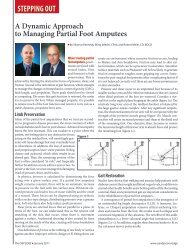
the end of stair contact (Fig. 3,left).The characteristics of the kneeand hip joints related to theprosthetic side have consequencesfor the next stair contact by thecontralateral side. Deviating fromapproximately symmetrical stairdescent by non-amputees, thetransfemoral amputee ‘falls’ ontothe sound leg, where the considerablyincreased initial peaks of verticalforce are markedly apparent(Fig. 3, right).This unphysiological loadinghas a striking effect on the biomechanicalcharacteristics of the anatomicalknee joint. The initiallylarge flexion moment, which presentsitself in the middle of theunphysiological knee flexion, canonly be compensated for by anincreased activation of the kneejoint extensor muscles and anincreased strain on the capsule andligament structures. Further cluesconcerning these compensatoryeffects may be revealed in furtherstudies through the addition ofEMG measurements. Overloadingof the contralateral extremity ismeasurable with all three testedReferences:joints, but has proven to be noticeablyless with use of the C-Leg. Itcan be derived from these resultsthat for amputees the secure functionalproperties (Koecher, 2001)and joint characteristics of the C-Leg contribute to the protection ofthe sound limb.[1] Andriacchi, T., G. Andersson, R.Fermier, D. Stern, O. Galante: Astudy of lower-limb mechanicsduring stair.climbing, Journal ofBone and Joint Surgery 62-A, 5(1980), 749-757[2] Blumentritt, S., H. Scherer, T.Schmalz: Ganganalyse von Oberschenkelamputiertenmit einemKniegelenk mit Rotationshydraulik,Med.Orth.Tech. 118 (1998), 51-61[3] McFadyen, B., D. Winter: An integratedbiomechanical analysis ofnormal stair ascent and descent. J.Biomechanics, 21 9 (1988), 733-744[4] Dietl, H., R. Kaitan, R. Pawlik, P.Ferrara: C-Leg – ein neues Systemzur Versorgung von Oberschenkelamputationen,Orthopädie-Technik49 (1998), 197-211[5] Köcher, L.: Das KniegelenksystemC-Leg – Klinische Versorgungsstatistik.Med.Orth.Tech. 121 4(2001), 129-134[6] Kastner, J., R. Nimmervoll, P. Wagner:Was kann das C-Leg? GanganalytischerVergleich von C-Leg,3R45 und 3R80, Med.Orth. Tech.119 (1999), 131-137[7] Schmalz, T., S. Blumentritt, K. Tsukishiro,L. Köcher, H. Dietl: Energyefficiency of trans-femoral amputeeswalking on computer-controlledprosthetic knee joint „C-Leg“.Kongressband 9. Weltkongress derInternational Society for Prostheticsand Orthotics (1998), 455-460Author contact information:Dr. T. SchmalzOtto Bock Research and DevelopmentBiomechanics LaboratoryHermann-Rein Str. 2a37075 GöttingenGermanyOrthoticsJ. SmitsAppropriate Patient Selectionfor A Carbon CompositeDynamic Response AFOWith he introduction of thermoplasticsin the late 1960’s and morerecently the focus on the physiciantherapist-orthotistteam approachto management of gait, numerousAFO designs emerged.Orthopädie-Technik <strong>Quarterly</strong>, <strong>English</strong> edition II/2004The Off-the-Shelf PLS (PosteriorLeaf Spring) serves as an excellentorthosis to assess function andpatient acceptance. But, rarely canit be modified sufficiently toaccommodate the patient’s neurophysiologicalor biomechanicalcomfort needs or long term wear.The MAFO, acronym for MoldedAFO, is frequently the orthosis ofchoice for weak dorsiflexors and toaddress issues of mild spasticity.But for your patients with M-Linstability, weak plantarflexors,moderate-severe spasticity, contracturesor deformities – more plasticto obtain a firmer grasp of theanatomy is generally required. Theincreased strength and coverage ofthe Semi-solid AFO better addressesat least the moderate stages ofthese deficiencies or conditions.Yet, still does not provide supportfor the severe stages. For the severestages, we often are forced to thesolid ankle AFO, offering optimumgrasp of the extremity and rigidity.However, the solid AFO basicallyimmobilizes the foot and is not recommendedwhen there is opportunitythat ankle motion mayincrease function. It also must beconsidered that immobilization isgoing to have a negative affect on7
PLS MAFO Semi-Solid UCBL Mod. UCBLmid-foot structures. The UCBL(University of California-BerkeleyLaboratory) and modified UCBL isconsidered when the patient canachieve heel strike in the stancephase, when there is hypertonicfoot reflex activity, and occasionallyfor mild-moderate spasticity. Itshould not be considered for thepatient with fixed equinus or patient’swho won’t wear recommendedshoes which offer addedextrinsic support. With the FloorReaction AFO, we are able to influenceknee extension moments – avery important benefit in our goalto optimize function. And then,almost all these designs are offeredwith various configurations ofjoints for articulation, when youwant to minimize potential forlocking up any joint completely oroffer control of the knee in thesagittal plane. There are as manytypes of joints as there are types ofAFOs, ranging from: free motion,limited range of motion, locking,to motion assist/resistance.In late 80’s and early 90’s, anothernew technology made its entranceinto the O&P industry –Carbon Composites. The uniqueenergy reflecting properties, variablestrength-rigidity-flexibility, andlightweight made it a natural forthe prosthetic feet. These sameproperties are of equal value for orthotics,and offer us a revolutionarynew perspective on the design,appearance, and function ofankle foot orthoses to enhance gaitfor the neurologically impairedextremity. In the following paragraphs,I will reference one particulardesign carbon composite orthosis,called “ToeOFF”, to furtherexemplify how the unique propertiesof this material can offerfunctional and cosmetic benefits inan AFO developed for managementof footdrop.When compared to plastic, thecomposites significantly reduce theweight of the orthosis, thus reducingthe weight the patient must liftwith the already neurologicallyimpaired extremity. The orthosiscan be made extremely thin so itcan easily fit into most standardshoes without increasing shoe size,thus increasing patient compliance.This particular orthosis has an anteriorshell which supports functionof the soleus – slows down forwardmomentum of tibia moving overfixed foot while femur keeps going –to create knee extension. The energyreflecting properties take advantageof momentum and gravity atthis stage and start to “load” – likejumping on a diving board. Theanterior shell then supports anteriortibialis in picking up the toe forclearance at toe-off. Fiberglass wasselected for the cuffs because of itsflexibility, allowing the cuffs tocomfortably fit varying calf sizes.Carbon fiber in the lateral strut providesrequired strength and rigidityfor good medial-lateral stability.However, this technology doesnot come without drawbacks. Boththe materials and the fabricationprocess is considerably moreexpensive than plastic. Further, atleast with the thermo-set matrixused in ToeOFF, it cannot be heatmolded.Yet, the functional benefitsfor the patient can be so significantthat in the following paragraphsI will review patient selection,physical examination, and alternativemethods for achieving properalignment, comfort, and gait optimization.The pre-fitting evaluationis quite similar to what hasbecome standard with plastic AFOs:Basic intake information– Foot length– Patient weight– Body type– Activity level– ExpectationsOpen Chain Assessment– Ankle ROM– Calcaneal ROM– “Lock-up” mechanism– Callus formation– Skin conditionCheck for calcaneal range ofmotion and whether the heel locksup when inverted and unlockswhen everted. Check for plantardorsiflexionrange of motion.Callus formation and skin conditioncan give you some immediateinsight into pressure distributionwhen walking.Barefoot WalkingBarefoot walking is important asit is the only way you can visuallyassess the movements of the foot.Does the mid-foot retain or loose itsstructural integrity? Does the heelcome off the ground at the appropriatetime for normal gait function?Are there any obvious knee orhip deficits or compensations?– Calcaneal ROM– Midfoot stability– Heel rise timing– Proximal deficitsWalking with ShoesExamine walking with shoes toassess the amount of support exi-8 Orthopädie-Technik <strong>Quarterly</strong>, <strong>English</strong> edition II/2004
NEWMore Patients ChooseSofTec® OAThe Bauerfeind Medical Line offers you a comprehensive selection of proven orthopedicproducts for the treatment of major joints. From active and stabilizing supports, toviscoelastic inserts to multifunctional orthoses, the line includes many new featuresand optimized functional designs. Please contact us for further details on professionalBauerfeind products for active patients.Rev. 0-04/04Bauerfeind Orthopädie GmbH & Co. KGArnoldstraße 15D-47906 KempenTel. +49(0)2152 - 20 81 36Fax +49(0)2152 - 20 81 38www.bauerfeind.comMembers of the Bauerfeind GroupBauerfeind <strong>USA</strong>, Inc.55 Chastain Road, Suite 112<strong>USA</strong>-Kennesaw, GA 30144Tel. +1 800-4233405Fax +1770-4298477www.bauerfeindusa.com
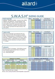
PLSMAFOSemi-solid AFOSolid AnkleUCBL & Modified UCBLFloor ReactionDynamic Carbon CompositeIndications– Temporary evaluations– Weak dorsiflexors– Mild spasticity– Weak dorsiflexors– Weak plantarflexors– Moderate M-L instability– Moderate spasticity– Mild contractures– Maximum stability– Gross instabilities– Moderate + spasticity– Protect unstable midfoot– Ability to achieve heel strike instance phase– Need for reduction of hypertonicfoot reflex activity– Mild-Moderate spasticity– Weak dorsiflexors– Mild spasticity– Need to influence knee extension– Weak dorsiflexors/planterflexors– Mild M-L instability– Mild to moderate spasticity– Need to influence kneeflexion/extension– Need for gait trainingContraindications– Any definitive use– M-L instability– Weak plantarflexors– Moderate + spasticity– Contractures– Deformities– Severe M-L instability– Severe spasticity– Severe contractures– When some ankle motion increasesfunction– When mid-foot integrity needsprotection– Fixed equinus or reflexogenicfoot deformity– Patient compliance for low-heel,lace or Velcro closure shoes– Inability to follow-up– Fixed equinus or reflexogenicfoot deformity– Patient compliance for good supportshoes– Fixed equinus or reflexogenicfoot deformity– Moderate to severe spasticity– Patient compliance for good supportshoessting shoes provide during gait.Compare the heel lift timing andproximal deficits to what youobserved when walking barefoot.– Heel lift timing– Proximal deficits– Changes vs. barefootObjective DataUsing just a stop watch and 10meter runway, it is easy to gatherobjective velocity, cadence, andstride length. Subjectively assesssingle support time. Compareresults before and after fitting withthe Carbon Composite AFO.– Velocity Distance:(10 meters)/Time– Cadence:# Steps/Time (seconds)– Stride Length:Distance (10 meters)/# StepsFitting and ModificationShoe SelectionA good support shoe is mandatory.A firm heel counter andshank, laces and rubber sole withtoe-lift are highly recommended.A removal inner sole allows easyinsertion of AFO shell. This carboncomposite AFO has a 12-15mm(depending on size) toe-to-heelheight differential. If necessary,increase or decrease the heel of theshoe to correspond. A rocker-styletoe-end will further help preventthe scraping of the toes in the ground.Size SelectionFor this carbon composite AFO,there are four sizes of what I shallrefer to as “shells” since it does notbecome an orthosis until the modificationsare complete. These shellsvary in footplate length, height ofthe anterior shell, and degree ofrigidity and flexibility. The manufacturerprovides a sizing chart,based on the footplate length.However, serious considerationshould be given to all the parametersindicated in the chart above.For example, for a patient with asmall foot but very stocky build, Iwould consider using a larger sizeshell than the sizing guide recommends,as I feel the greater rigiditywould be required to support theexcess weight. The same for a patient,such as one with GuillianBarres Syndrome – they generallyrequire optimum tibia support so Iwould consider a larger size shellsince the anterior support is longerand again offers greater rigidity.For a patient that is veryactive, I may consider selectinga size smaller than thesizing guide suggests as Ithink they may benefit fromthe greater flexibility in thesmaller size. And so on andso on.AlignmentAlignment of the orthosisto the tibia could be comparedto the importance of the10 Orthopädie-Technik <strong>Quarterly</strong>, <strong>English</strong> edition II/2004
anatomical alignmentof a prosthetic leg. Thisalignment affects bothcomfort and gait pattern.It also controls thecritical alignment of thelateral strut to appropriatestructures at themid-foot. The continuousgoal should be toensure even pressurealong the entire surfaceof the anterior shell tothe tibia. With the legin neutral position(ankle at right angle), aplumb-line should dropjust behind the knee axis and hitthe floor at the cuboid bone.When the strut does not align asdescribed, shift the footplate forwardor backward to locate ideallocation for even pressure distribution.If necessary, trim the footplateat the toe end and add leather,rubber, or plastic to extend thelength at the heel-end to preventthe footplate from shifting.Patient ComfortTibial pressure can easily berelieved with padding inside theanterior shell. Covering the entiresurface can shift the anterior shellforward resulting in poor alignment.Instead pad only the sides,forming a relief channel for thetibia. You can custom shape yourown padding or for this particularcarbon composite orthosis, themanufacturer offers an optionalpadding kit that is adhered with athin self-adhesive Velcro.If there is pressure over theinstep, pad the medial-distal aspectof the lateral strut to shift the footmedially.Foot BiomechanicsTo optimize gait and ensure productdurability, correct positioningof the foot to achieve a position asclose to neutral as possible whenweight bearing. Be certain anymodifications allow the calcaneousto move through neutral frominversion during swing to eversionduring stance.PronationFor mild pronation control,posting of the medial aspect of thecalcaneous on the footplate, and oruse of a rigid insole, to deceleratethe pronation moment may be suf-Orthopädie-Technik <strong>Quarterly</strong>, <strong>English</strong> edition II/2004ficient. It is crucial tomonitor progression ofpronation as pronationimbalance left untreatedcan lead to seriousjoint separation problemsand even subluxation.Consider customorthotics whenthere are any signs ofprogression.Hyper-pronationThe hyper-pronatedfoot presents – with thearches of the feet completelyflattened andthe joints displaced to the pointwhere they can be considered subluxed– great challenges. This definitelyrequires the addition of acustom orthotic to the carboncomposite insole.SupinationFor supination, post the lateralaspect of the footplate to acceleratepronation. If there is also forefootinvolvement, a custom orthosiswith first ray cut-out should befabricated and cemented onto thecarbon composite footplate.Ground ReactionThe anterior shell design of thiscarbon composite orthosis will initself influence the knee extensionmoment. To encourage even moreextension and minimize the flexionforces, decrease heel height.This shifts the proximal section ofthe anterior shell backward toencourage knee extension earlierin the gait cycle. To encouragemore knee flexion and delay theextension moment, increase heelheight. This shifts the proximalsection of the anterior shell forwardto encourage more knee flexion.The anterior shin plate willinfluence the position of the knee.To apply an influence towardincreased valgus forces, wedge thebottom of the footplate on thelateral side – for valgus forces – tothe medial side.Patient EducationGuidelinesPatient education is criticallyimportant to the overall success ofany orthotic device, and the carboncomposite AFO’s are no exception.Great skill and care on the partof the orthotist can be over-riddenby patient non-compliance. Thefollowing guidelines must beexplained to each patient:– Do not “toe-walk” up stairs orclimb ladders on the ball of thefoot. This can cause excessivedorsiflexion stress on the deviceand potentially lead to earlydelamination– Do not take excessively long stridelengths. This can also causeexcessive dorsiflexion and potentiallylead to delamination.Caution patient not to “lean” onthe device for extra propulsion.– Do not continuously squat toreach lower levels. This cancause excessive dorsiflexion andpotentially lead to delamination.– Do not wear the device withfootwear that has not beenapproved by the orthotist.Wearing inappropriate footwearcan limit gait benefits, causeharmful effects to proximalstructures, and lead to productfailure.– Do not expose the device tohigh temperature extremes.– Do follow your orthotists instructionsabout use of the product,including toe walking upstairs, excessive stride length,shoe selection, etc.– Do wear knee high cotton sockswhile wearing this device.Change on a daily basis.– Do change the SoftKIT liner atleast twice a week, and more frequentlyunder extreme heat andhumidity conditions. One linershould be worn while the otheris in laundry.– Do check the condition of thefoot and lower leg on a dailybasis. Inspect all contact areas,with a mirror if necessary, forany signs of skin irritation or -breakdown.– Do report any abnormal conditionsto the orthotist, includingbut not limited to skin redmarks, pinching sensation, pressuresensation, skin abrasions,abnormal shoe wear, etc.Author contact information:J. SmitsHolterbergweide 265709 HelmondThe Netherlands11
ProstheticsG. StarkOverview of HipDisarticulation ProsthesesSince only two percent of allamputations are at hip disarticulationlevel [2], the average prosthetistmay not be able develop a consistentprosthetic fitting protocolwith regard to evaluation, impressiontaking, modification, componentryselection, and alignment.As with other proximal amputationlevels, hip disarticulation prosthesessuffer a higher rejectionrate due to weight, increased energyrequirements, and proximalinterface enclosure. This has beenanswered with the standard use ofendoskeletal componentry, softerinterface materials, and more dynamicdesigns. The energy requirementsfor the hip disarticulationamputee have been estimated tobe as much as 200 percent greaterthan normal human ambulation[1].Successful fitting of the hip disarticulationprosthesis hinges onthe evaluation of balance, lowerabdominal tissue condition, andpelvic lordosis. Balance is neededto successfully don and ambulatewith the limb with minimal assistiveaids. If this is not present, theclient may not be considered agood prosthetic candidate [1]. Thecreation of a properly fitting interfaceis also critical since it mustprovide geometries for comfortableaxial support, ambulation, and suspensionwhile keeping size to aminimum. Abdominal conditionmust be evaluated for volumereduction and shaping to create avolumetrically tight and accurateA-P fit between the sacrum andlower abdomen [7]. To be successfulin gait, the amputee should beable to demonstrate active pelviclordosis using the muscles of thelower back and abdomen. Pelviclordosis insures that the patientcan take a normal stride length onthe sound side. Pelvic flexion mustalso be evaluated, since this is themain biomechanic worksourceFig. 1used late in stance to initiate kneeflexion. The most successfulamputees are those that are able tomaintain a low weight so that themaximum abdominal range ofmotion may be captured. The presenceof any redundant or fleshytissue should be noted since itmust be contained and shaped tocreate reaction surfaces for properprosthetic function (Fig. 1). TightM-L measurements are also necessaryto preserve M-L stabilityduring gait. M-L measurementsshould be recorded over the iliaccrests and between the trochanterand the iliac crests [7] (Fig. 2).The bony anatomy should alsobe evaluated with respect to ischialload bearing and the presence of afemoral head. Bony prominencesof the pubis and iliac crests shouldalso be noted for relief within theinterface. It should be noted thatany gluteal tissue available shouldbe utilized for axial loading.There are two main types ofimpression taking for the hip disarticulationinterface: Using FormingBlocks [7] and Total SuspensionCasting [3]. The technique usingforming blocks begins by markingthe iliac crests, costal margin,pubis, femoral head or joint, andFig. 2ischium. Plaster is wrapped overthe lower limb from the perineumto 2 inches proximal to the iliaccrests and reinforcing splints areadded to the ischial area. The iliaccrests are modified using plasterrope, surgical tubing, or radiatorhose to forcefully compress the tissuecircumferentially and downward.One method involves usingsqueezing the plaster rope by twistingit around a dowel or hammerhandle to attain good loading. Therope should be flattened in thesacral area to avoid localized pressureover the spinous processes [3].The patient is then seated on a flatsurface and 45 degrees formingblocks are placed anterior andposterior to create A-P reaction surfacesnecessary for ambulation.The posterior block is placed toload the gluteus and provide somerelief for the ischium. The anteriorblock is placed to help form thegeometry for the hip attachmentplate with 5 degrees of external rotation[7]. It should be noted thatthe posterior forming block is neededto provide counterpressure tomaintain contact with the anteriorblock (Fig. 3). This common methodworks well for thinner clientswith good muscle tone. For thosewho have soft abdominal tissue,the blocks may tend to distort themold by expanding the M-L.Total suspension casting is anothermethod utilized to contain thesoft tissue and achieve a better12 Orthopädie-Technik <strong>Quarterly</strong>, <strong>English</strong> edition II/2004
Fig. 3volumetric loading within theinterface. With this approach, thecasting garment is suspended fromthe ceiling using a mechanicalwinch device. When the supportheight has been adjusted to wherethe iliac crests are even, the samelandmarks are indicated and theplaster splints are added. The iliaccrests are modified with the sameroping technique and ischium iscupped in the palm of the hand.The disadvantage of this techniqueis that the anterior surface is notclearly defined. Some prosthetistsutilize both casting methods bycontaining the tissue in suspensionand then using forming blocks toplace the hip joint.Often the initial cast taken doesnot reduce the volume adequatelyto create a tight interface. For thisreason, the client should recline inthe cast and the anterior panelshould be cut. The anterior sectionis squeezed together, lapping theanterior panels. The location iskey marked and the cast is removed.Before the mold is filled, thecast is again squeezed to this pointand secured to eliminate extrainterface volume and maintain circumferentialtension [5].Many different hip disarticulationinterface shapes will fit the clientcomfortably, but may not alsoprovide adequate suspension orlordotic capture. Substantial modificationis necessary to achievecomfort and function. After thecast has been removed, the landmarksare remarked. Plaster isremoved from the anterior portionof the mold avoiding the pubis.When the abdomen is more pendulous,flattening is adequatewhile thinner individuals mayhave a slight concavity to load theabdomen. The posterior sacral areais also flattened along the lowerback to maintain tight A-P pressure.Half inch of material should beremoved between the trochanterand iliac crest avoiding the ASISand the iliac crests from the measuredM-L to insure a tight fit. Thesuperior iliac crest modificationsmade with the plaster rope arethen deepened quarter to half incheven to the crests [7]. Some loadingof the gluteus is also advisableto avoid too much ischial pressure.Some prosthetists have suggestedthat medial ischial pressureis advantageous, but achieves littlebiomechanically without a distalreaction point. Cupping of theFig. 4ischium seems to be the most comfortablegeometry. Relief may haveto be added to the pubis, iliaccrests, and ASIS. The socket maybe made as a side opening or anterioropening configuration althoughthe latter predominatesbecause it is easier to don and doff.The trimlines are approximately 2inches proximal to the iliac crestsand through the perineum. Asmall suspension band is cut thatprovides relief on the contralateralASIS.Endoskeletal componentry hasbecome standard for hip disarticulationprostheses with its requirementsfor lightweight and stability.However, special considerations forcomponentry selection should bemade to optimize function. Dynamicresponse feet are commonlychosen for its lightweight design.Only in the more active patient cantrue dynamic responsiveness beobserved with the slowed gait ofthe hip disarticulation patient. Aninexpensive SACH foot with a softheel cushion can also be used toincrease knee stability at heel strikeby shifting the reaction line anterior.Although single axis and multiaxialfeet may be used to increasestability, they add substantialweight to the distal end of the limb.Single axis knees are the predominatechoice for HD since they arelightweight and friction control isadequate for clients with a singlecadence speed. Stance controlknees should not be chosen sincethere is a downward thrust whenthe pelvis lordosis anteriorly toinitiate knee flexion. This engagesthe stance control brake and impedesnormal knee flexion. Since stabilityis provided with alignment ofthe hip and knee, added stabilityfeatures are not necessary unlesswhen dealing with a more activeusers. These clients may requirethe stability feature for uneven terrain,which is then adjusted tominimally hinder knee flexion.Polycentric knees are often chosenfor active users who will toleratethe increased weight, desire thevariable stability, and shin shorteningfeatures. Shin shortening isattractive to the hip disarticulationprosthetic wearer because there isno hip flexion and little knee flexionat midswing, which help shortenthe anatomic leg. The hip disarticulationprosthesis often feels“long” and must be 6-12mm shorterthan the anatomic leg. Hydrauliccontrol is not often usedbecause the hip disarticulationamputee is not generating the gaitspeeds needed to justify the increasedweight, but may help initiatehip flexion during swing. Originally,the hip joint was mountedlaterally, near the anatomic hipjoint center. The joint was locked14 Orthopädie-Technik <strong>Quarterly</strong>, <strong>English</strong> edition II/2004
Orthopädie-Technik <strong>Quarterly</strong>, <strong>English</strong> edition II/2004for standing and walking, thenunlocked for sitting [4]. In 1954Ian Mc Laurin introduced theCanadian Hip Disarticulation configurationthat is standard to thisday with an anteriorly mountedhip joint that was held stableduring stance using biomechanicalstability of a posteriorly placedreaction line [1,5]. Currently thereare a variety of hip joints that differwith regard to attachment and function.The older endoskeletal designshave double anterior andposterior free motion hinges thatoffer simple hip extension (withrubber bands) or a manual hip lock.These are relatively lightweight andoffer transverse rotation and sagittalplane adjustment, but havedistal componentry that can makesitting a problem. Newer modularsystems are more integrated andhave attachments that make sittingeasier. These are usually mountedanterior to a flat or dished plate andhave an internal adjustable springhip extension assist. A slight amountof ab/adduction adjustment isavailable along with and flexion/extension adjustment. This commondesign is also offered in a pediatricsize [7].Different pylons and attachmentcomponents are also available. 22mm pediatric sizes are availablealong with the more common 30mm pylon. Also 34 mm pylons areavailable for heavier loads. It is importantto include an angled tubeclamp above the knee to receivethe upper femoral pylon since thisusually has a considerable anteriorangle. Carbon composite strutsystems have been introduced thatoffer more dynamic motion andshock attenuation during stance.The strut flexes when loaded andreleases its force at the beginningof swing to increase hip and kneeangular acceleration, which canhelp speed the step [8]. The disadvantageof this system is that thespring is lessened as the strut isshortened and too soft a springmay dampen the initial anteriorlordotic movement. In addition,special attachments for the hip andknee are required to accommodatethis system.The hip disarticulation interfacemust serve three purposes: M-Lsupport, comfortable suspensionover the iliac crests, and surfacesfor lordotic action. Laminated interfacescan be fabricated with differentstiffness of plastic for flexibilityproximally and rigidity at theattachments. Also, it is mucheasier to achieve an accurate interiorsurface since the attachmentplate is laminated within thesocket shell in a one-step process.New thermoplastic materials havebeen developed that greatly increasesocket comfort especially overFig. 5the iliac crests. The main difficultywith thermoforming comes in thefabrication of the inner attachment.Normally a soft anterior padis placed on the mold before formingthe flexible inner liner. Abuild-up is then made for theattachment and the frame is laminatedor made of stiffer thermoplastic.A plastic or foam cover for thehip joint can then be made andglued to conceal the hip joint.Kempfer suggests using the anteriorpanel cut from a polyethylenecheck socket [6]. While thermoformingoffers a variety of materialsReferences:[1] Atlas of Limb Prosthetics: Chapter21B/Prosthetic Management. Vander Waarde, T., Michael, J., St.Louis, MO, Mosby-Yearbook, 1992.[2] Limb Prosthetics. Wilson, A.B., 6thed. New York, NY, Demos Publications,1989.[3] Hip Disarticulation Fitting Manual,Northwestern University ProstheticOrthotic Center, Chicago,IL, 1991.[4] Human Limbs and Their Substitutes.Klopsteg, P., Wilson, P.,New York, NY, McGraw-Hill, 1954.and construction ease, it is thickerand the hip plate attachment is notas integrated as in lamination.Stability of the hip disarticulationprosthesis relies primarily onthe alignment of the prosthesis.The bench alignment involves projectinga line from the hip centerthrough the knee center. This lineshould fall 25-50 mm behind theheel of the shoe (Fig. 4). In thefrontal plane, the hip joint shouldbe placed 10mm lateral to the frontalquarter mark with 5 to 10 degreesof external rotation to matchanatomic lower limb rotation [3](Fig. 5). Sagittally the hip joint placementis established with the formingblocks. The knee center andmidfoot are placed in relationshipto a plum line from the bisectionof the interface based on theirdesign. For example a single axisknee is placed 15mm posterior anda dynamic response midfoot is 20mm anterior to the bisection [3].The length of the prosthesis is 12mm shorter than the sound side sothat the foot can clear the floorduring midswing. During dynamicalignment, the hip joint should beadjusted so that is not engagedbefore midstance during forwardpelvic lordosis [3]. As a note, thecosmetic cover may have to be preformedto lessen the amount tensionthat could cause premature hipflexion [3].Author contact information:Gerald Stark (BSME, CP, FAAOP)Director of Product Development &EducationFillauer, Inc.2710 Amnicola Hwy.Chattanooga, TN 37407<strong>USA</strong>[5] Diagonal Type Socket for Hip DisarticulationAmputees, Mc Laurin,C.A., Hampton, F., NorthwesternUniversity, VA Contract No.V1005M 1079, May, 1962.[6] Technical Note: Light Weight HipDisarticulation Prosthesis. Kempfer,J., Journal of Prosthetics andOrthotics, 1991, 3:1.[7] Modular Hip Disarticulation ProsthesisVideo, Otto Bock-<strong>USA</strong>, Minneapolis,Minnesota.[8] Littig Hip Strut System Video,USMC, Pasadena, California.15
Just Seal-In and go!Iceross ® TF Seal-In StandardIceross ® TF Seal-In Conical• Excellent suspensionand rotational control• Enhanced comfort• Ease of donningIntroducing the Iceross ® TF Seal-In LinerIt’s no longer necessary to perform an awkward donning process in order to enjoy the benefits of asuction socket. With the Iceross TF Seal-In liner the user simply rolls the liner on and steps into thesocket. This liner brings the same breakthrough technology to transfemoral amputees that we recentlyintroduced for transtibial amputees. It provides a stable and intimate fit in a comfortable, reliablesuction suspension system that is easy to live with.Please visit us at our booth in hall 2, F09/E10, Orthopädie + Reha-Technik World Congress in Leipzigwww.ossur.com