NGC-30 vs. NGC-40 - Pentair Thermal Management
NGC-30 vs. NGC-40 - Pentair Thermal Management
NGC-30 vs. NGC-40 - Pentair Thermal Management
- No tags were found...

Create successful ePaper yourself
Turn your PDF publications into a flip-book with our unique Google optimized e-Paper software.
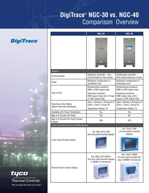
DigiTrace ® <strong>NGC</strong>-<strong>30</strong> <strong>vs</strong>. <strong>NGC</strong>-<strong>40</strong>Comparison Overview<strong>NGC</strong>-<strong>30</strong><strong>NGC</strong>-<strong>40</strong>GeneralControl BoardsPanelArea of UseHazardous Area Rating(North American Standards)Multipoint Controller – Onecontrol board for five circuits.Multipoint configuration incentralized rack.Nonhazardous locations:EMR or SSR output relay.Hazardous locations:EMR output relay with Z Purgeor SSR output relay.Class I, Division 2, Groups A–DClass I, Zone 2, Group IICTemperature Rating: T4Single-point controller –One control board per circuit.Multipoint configuration incentralized rack.Nonhazardous locations:EMR or SSR output relayHazardous locations:EMR output relay with Zpurge or SSR output relay.Class I, Division 2, Groups A–DClass I, Zone 2, Group IICTemperature Rating: T4Available with Power Distribution Yes YesMax # of Circuits Per Panel 60 80Max # of Circuits Per Touch ScreenDisplay260 320Local and Central Control and MonitoringLocal Touch Screen DisplayYes. <strong>NGC</strong>-UIT2-ORD(8.4-inch panel-mounted display)Yes. Touch 1500(15-inch panel-mounteddisplay)Yes. <strong>NGC</strong>-UIT2-ORD-R(8.4-inch wall-mounted displayin NEMA 12 enclosure)Yes. Touch 1500R(15-inch wall-mounted displayin NEMA 4 enclosure)Remote Touch Screen Display
<strong>NGC</strong>-<strong>30</strong> cont.<strong>NGC</strong>-<strong>40</strong> cont.Yes (digital status only)Yes (digital status only)Control Module’s Front Panel – DisplayCentral Monitoring and Control –Interface to DigiTrace SupervisorSoftware (DTS)Central Monitoring and Control– Interface to Distributed ControlSystems (DCS)Temperature SourcesSupported RTD TypesMaximum number of TemperatureSources Assigned to a CircuitTemperature Source SharingYesYes3-Wire 100 ohm platinumYesYes3-Wire 100 Ohm platinum2 or 3-wire 100 Ohm nickel iron2-Wire 100 Ohm nickel4 8YesThe <strong>NGC</strong>-<strong>30</strong> temperaturesources that are listed belowcan be assigned to any of theheat tracing circuits connectedto one User Interface Terminal(UIT2). RTDs can even beassigned to multiple heattracingcircuits.Local: One temperature inputstandard per controller connectdirectly to CRM or CRMSboard (hard wired).Input/Output (IO) Module: NoRMM2: Yes. Each RemoteMonitoring Module (RMM2)can accept up to 8 RTDs. Upto 128 RTDs from optionaldaisy-chained RMM2s canbe connected to the <strong>NGC</strong>-<strong>30</strong>system via one twisted pairRS-485 cable.PLI: Yes. Via optional PowerLine Interface (PLI) Modulethrough RS-485 network, eachPLI Module can accept upto 127 RTDs via SES or SPCTransmitters and 255 RTDs via700-TT Transmitters.YesThe <strong>NGC</strong>-<strong>40</strong> temperaturesources that are listed belowcan be assigned to any othercontrol module within thepanel. RTDs can even beassigned to multiple controlmodules.Local: One temperature inputstandard per controller connectdirectly to HTC or HTC3Module (hard wired).Input/Output (IO) Module:Up to four additional temperatureinputs can beconnected directly to oneoptional IO Module.RMM2 (Remote MonitoringModule): Future OptionPLI (Power Line InterfaceTechnology): Future Option2
ComponentsArchitecture<strong>NGC</strong>-<strong>30</strong> cont.Five circuits per control board.Four control boards per cardrack.<strong>NGC</strong>-<strong>40</strong> cont.ModularControl and Monitoring Module,Single-phase Heater<strong>NGC</strong>-<strong>30</strong>-CRM: Card RackModule for EMR output relay.Controls five circuits.<strong>NGC</strong>-<strong>30</strong>-CRMS: Card RackModule for SSR output relay.Controls five circuits.<strong>NGC</strong>-<strong>40</strong>-HTC moduleControl module for singlephaseheater with EMR orSSR output relay. Controlsone circuit.Control and Monitoring Module,Three-phase Heater<strong>NGC</strong>-<strong>30</strong>-CRM/CRMS controlssingle-phase and three-phaseheaters but monitors singlephase only.<strong>NGC</strong>-<strong>40</strong>-HTC3Control module for 3-phaseheater with EMR or SSRoutput relay. Controls andmonitors all phases of athree-phase heater.<strong>NGC</strong>-<strong>40</strong>-IO (optional)Each I/O module provides upto four additional RTD inputs.Input and Output ModuleNoIncluded in HTC/HTC3 modulesCurrent Transformer Module<strong>NGC</strong>-<strong>30</strong>-CTM3
<strong>NGC</strong>-<strong>30</strong> cont.<strong>NGC</strong>-<strong>30</strong>-CVM (optional)<strong>NGC</strong>-<strong>40</strong> cont.Voltage Monitoring ModuleNoPart of the Touch Screen, UserInterface Terminal (UIT2)Communications bridge module<strong>NGC</strong>-<strong>40</strong>-BRIDGECommunications ModulePower termination included incontrol boards CRM/CRMS forfive <strong>NGC</strong>-<strong>30</strong> circuits<strong>NGC</strong>-<strong>40</strong>-PTMRoutes power to maximum10 <strong>NGC</strong>-<strong>40</strong> modules.Power Termination ModuleCR20 circuits per card rack.Card RackNot required. Panel mountingon 35 mm DIN rails.Digital InputNoYes, each HTC, HTC3 and I/Omodule provides one multipurpose,programmabledigital input.Alarm Output – IndividualNoYes, each HTC, HTC3 andI/O module has a dry contactalarm output relay.Alarm Output – Common Yes YesSupports RMM2(Remote Monitoring Module)YesFuture optionSupports PLI(Power Line Interface Technology)YesFuture optionElectrical CharacteristicsHeating Cable Voltage 600 Vac 600 VacLine Current Measurement – L1 Yes YesLine Current Measurement – L2 No YesLine Current Measurement – L3 No YesGround-Fault Current MeasurementSingle-Phase: YesSingle-Phase: YesThree-Phase: Yes, 3 wire only Three-Phase: Yes, 3 or 4 wire4
<strong>NGC</strong>-<strong>30</strong> cont.<strong>NGC</strong>-<strong>40</strong> cont.Power Calculations Accumulator – L1 No YesPower Calculations Accumulator – L2 No YesPower Calculations Accumulator – L3 No YesPower Calculations Accumulator –Total PowerNoYesVoltage Range Measurement Yes NoCircuit Breaker Limiting – ProtectsHeater’s Upstream Circuit BreakerNoYesfrom TrippingPower Limiting – Controls MaximumOutput WattageYesYesSwitch Limiting – Protects SSR OutputSwitchNoYesHot Swap of the Modules No NoControlOutput Switches EMR, SSR EMR, SSRControl ModesControl Temperature SelectionWith EMR:• On/Off• PASC• Always on• Always offWith SSR:• On/Off• PASC• Proportional• Always on• Always offLowest temperature inputassigned to a circuit.With EMR:• On/Off• PASC• Always on• Always offWith SSR:• On/Off• PASC• Proportional• Always on• Always offTS1 or TS2 or TS3 or TS4 orTS5 or TS6 or TS7 or TS8 orAverage or LowestTS = Temperature SourceHigh Temperature Limit Cut-Out Yes YesTS Fail On Yes YesTS Fail Off Yes YesHeating Cable Temperature SetpointRangeAll Alarms Can Be Individually Definedas Latching or Non-latchingAll Alarms Can Be Individually Enabledor DisabledCommunicationsCommunications with DTS or DCS –MediaCommunications with DTS or DCS –Protocol–99°F to 900°F(–73°C to 482°C)NoThree latching alarms: Overcurrent, ground-fault trip andground-fault alarm. The restnon-latching.NoHard-wired serial communications(RS-232 or RS-485)10/100Base-T Ethernet LAN(Local Area Network)Internet-based WAN(Wide Area Network)Modbus ®–112°F to +1292°F(–80°C to +700°C)YesYesHard-wired serial communications(RS-232 or RS-485)10/100Base-T Ethernet LAN(Local Area Network)Internet-based WAN(Wide Area Network)Modbus5
Environmental InformationPanel Operating TemperaturePanel Storage Temperature<strong>NGC</strong>-<strong>30</strong> cont.With installed UIT2With distribution:14°F to 122°F (–10°C to50°C). Below 14°F (–10°C),space heater and thermostatmust be used.Without distribution:–13°F to 122°F (–25°Cto 50°C). Below –13°F(–25°C), spaceheater andthermostat must be used.Without installed UIT2With distribution:14°F to 1<strong>40</strong>°F (–10°C to60°C). Below 14°F (–10°C),space heater and thermostatmust be usedWithout distribution:–13°F to 122°F (–25°Cto 60°C). Below –13°F(–25°C), space heater andthermostat must be used.–13°F to 167°F(–25°C to 75°C)<strong>NGC</strong>-<strong>40</strong> cont.With installed Touch 1500With distribution:32°F to 122°F (0°C to50°C). Below 32°F (0°C),window cover, space heaterand thermostat must be used.Without distribution:32°F to 122°F (0°C to50°C). Below 32°F (0°C),window cover, space heaterand thermostat must be used.Without installed Touch 1500With distribution:14°F to 1<strong>40</strong>°F (–10°C to60°C). Below 14°F (–10°C),space heater and thermostatmust be used.Without distribution:–13°F to 1<strong>40</strong>°F (–25°C to60°C). Below –13°F (–25°C),space heater and thermostatmust be used.With installed Touch 1500–4°F to 1<strong>40</strong>°F(–20°C to 60°C)Without installed Touch 1500–13°F to 167°F(–25°C to 75°C)Worldwide HeadquartersTyco <strong>Thermal</strong> Controls<strong>30</strong>7 Constitution DriveMenlo Park, CA 9<strong>40</strong>25-1164USATel: 800-545-6258Tel: 650-216-1526Fax: 800-527-5703Fax: 650-474-7711info@tycothermal.comwww.tycothermal.comTyco and DigiTrace are trademarks of Tyco <strong>Thermal</strong> Controls LLC or its affiliates.Modubs is a trademark of Modubs Organization, Inc.Important: All information, including illustrations, is believed to be reliable. Users, however, should independently evaluate thesuitability of each product for their particular application. Tyco <strong>Thermal</strong> Controls makes no warranties as to the accuracy or completenessof the information, and disclaims any liability regarding its use. Tyco <strong>Thermal</strong> Controls’ only obligations are those inthe Tyco <strong>Thermal</strong> Controls Standard Terms and Conditions of Sale for this product, and in no case will Tyco <strong>Thermal</strong> Controls orits distributors be liable for any incidental, indirect, or consequential damages arising from the sale, resale, use, or misuse of theproduct. Specifications are subject to change without notice. In addition, Tyco <strong>Thermal</strong> Controls reserves the right to make changes—withoutnotification to Buyer—to processing or materials that do not affect compliance with any applicable specification.6© 2010 Tyco <strong>Thermal</strong> Controls LLC H58679 06/10