Experiment 18 â Frequency Shift Keying
Experiment 18 â Frequency Shift Keying
Experiment 18 â Frequency Shift Keying
- No tags were found...

Create successful ePaper yourself
Turn your PDF publications into a flip-book with our unique Google optimized e-Paper software.
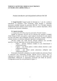
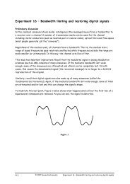
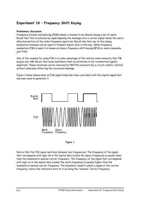
<strong>Experiment</strong> <strong>18</strong> – <strong>Frequency</strong> <strong>Shift</strong> <strong>Keying</strong>Preliminary discussion<strong>Frequency</strong> division multiplexing (FDM) allows a channel to be shared among a set of users.Recall that this is achieved by superimposing the message onto a carrier signal inside the user’sallocated portion of the radio-frequency spectrum. Recall also that any of the analogmodulation schemes can be used to transmit digital data in this way. When frequencymodulation (FM) is used it is known as binary frequency shift keying (BFSK or more commonlyjust FSK).One of the reasons for using FSK is to take advantage of the relative noise immunity that FMenjoys over AM. Recall that noise manifests itself as variations in the transmitted signal’samplitude. These variations can be removed by FM/FSK receivers (by a circuit called a limiter)without adversely affecting the recovered message.Figure 1 below shows what an FSK signal looks like time-coincident with the digital signal thathas been used to generate it.Figure 1Notice that the FSK signal switches between two frequencies. The frequency of the signalthat corresponds with logic-0s in the digital data (called the space frequency) is usually lowerthan the modulator’s nominal carrier frequency. The frequency of the signal that correspondswith logic-1s in the digital data (called the mark frequency) is usually higher than themodulator’s nominal carrier frequency. The modulator doesn’t output a signal at the carrierfrequency, hence the reference here to it as being the “nominal” carrier frequency.<strong>18</strong>-2© 2007 Emona Instruments <strong>Experiment</strong> <strong>18</strong> – <strong>Frequency</strong> <strong>Shift</strong> <strong>Keying</strong>
FSK generation can be handled by conventional FM modulator circuits and the voltagecontrolledoscillator (VCO) is commonly used. Similarly, FSK demodulation can be handled byconventional FM demodulators such as the zero crossing detector (refer to the preliminarydiscussion of <strong>Experiment</strong> 12 for an explanation of this circuit’s operation) and the phase-lockedloop. Alternatively, if the FSK signal is passed through a sufficiently selective filter, the twosinewaves that make it up can be individually picked out. Considered on their own, each signal isan ASK signal and so the data can be recovered by passing either one of them through anenvelope detector (refer to the preliminary discussion of <strong>Experiment</strong> 8 for an explanation ofthe envelope detector’s operation).The experimentIn this experiment you’ll use the Emona DATEx to implement the VCO method of generating anFSK signal. Digital data for the message is modelled by the Sequence Generator module. You’llthen recover the data by using a filter to pick-out one of the sinewaves in the FSK signal anddemodulate it using an envelope detector. Finally, you’ll observe the demodulated FSK signal’sdistortion and use a comparator to restore the data.It should take you about 40 minutes to complete this experiment.Equipment Personal computer with appropriate software installed NI ELVIS plus connecting leads NI Data Acquisition unit such as the USB-6251 (or a 20MHz dual channel oscilloscope) Emona DATEx experimental add-in module two BNC to 2mm banana-plug leads assorted 2mm banana-plug patch leads<strong>Experiment</strong> <strong>18</strong> – <strong>Frequency</strong> <strong>Shift</strong> <strong>Keying</strong> © 2007 Emona Instruments <strong>18</strong>-3
ProcedurePart A – Generating an FSK signal1. Ensure that the NI ELVIS power switch at the back of the unit is off.2. Carefully plug the Emona DATEx experimental add-in module into the NI ELVIS.3. Set the Control Mode switch on the DATEx module (top right corner) to PC Control.4. Check that the NI Data Acquisition unit is turned off.5. Connect the NI ELVIS to the NI Data Acquisition unit (DAQ) and connect that to thepersonal computer (PC).6. Turn on the NI ELVIS power switch at the back then turn on its Prototyping BoardPower switch at the front.7. Turn on the PC and let it boot-up.8. Once the boot process is complete, turn on the DAQ then look or listen for theindication that the PC recognises it.9. Launch the NI ELVIS software.10. Launch the DATEx soft front-panel (SFP) and check that you have soft control over theDATEx board.11. Locate the Sequence Generator module on the DATEx SFP and set its soft dip-switchesto 00.12. Slide the NI ELVIS Function Generator’s Control Mode switch so that it’s no-longer inthe Manual position.13. Launch the Function Generator’s VI.14. Press the Function Generator VI’s ON/OFF control to turn it on.15. Adjust the Function Generator using its soft controls for an output with the followingspecifications:Waveshape: Sine<strong>Frequency</strong>: 10kHzAmplitude: 4Vp-pDC Offset: 0V<strong>18</strong>-4© 2007 Emona Instruments <strong>Experiment</strong> <strong>18</strong> – <strong>Frequency</strong> <strong>Shift</strong> <strong>Keying</strong>
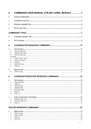
16. Connect the set-up shown in Figure 2 below.Note: Insert the black plugs of the oscilloscope leads into a ground (GND) socket.MASTERSIGNALSSEQUENCEGENERATORFUNCTIONGENERATOROLINECODE1100kHzSINEOO NRZ-LSYNCO1 Bi-O1O RZ-AMI11 NRZ-MXANALOG I/ OSCOPECH A100kHzCOS100kHzDIGITAL8kHzDIGITAL2kHzDIGITAL2kHzSINEYCLKSPEECHGNDGNDACH1 DAC1ACH0 DAC0VARIABLE DC+CH BTRIGGERFigure 2This set-up can be represented by the block diagram in Figure 3 below. The SequenceGenerator module is used to model a digital signal and its SYNC output is used to trigger thescope to provide a stable display. The Function Generator’s VCO facility is used to generatethe FSK signal.MasterSignalsSequenceGeneratorFunc. Gen.VCODigital signalTo Ch.A2kHzClockCLKSYNC10kHz restfrequencyFSK signalTo Ch.BSYNCTo Trig.Digital signal modellingFSK generationFigure 3<strong>Experiment</strong> <strong>18</strong> – <strong>Frequency</strong> <strong>Shift</strong> <strong>Keying</strong> © 2007 Emona Instruments <strong>18</strong>-5
17. Set up the scope per the procedure in <strong>Experiment</strong> 1 with the following change:Trigger Source control to TRIGGER instead of CH A<strong>18</strong>. Activate the scope’s Channel B input to observe the Sequence Generator module’s outputand the FSK signal out of the VCO.19. Compare the signals.Question 1What’s the name for the VCO output frequency that corresponds with logic-1s in thedigital data? Tip: If you’re not sure, see the preliminary discussion.Question 2What’s the name for the VCO output frequency that corresponds with logic-0s in thedigital data?Question 3Based on your observations of the FSK signal, which of the two is the higher frequency?Explain your answer.Ask the instructor to checkyour work before continuing.<strong>18</strong>-6© 2007 Emona Instruments <strong>Experiment</strong> <strong>18</strong> – <strong>Frequency</strong> <strong>Shift</strong> <strong>Keying</strong>
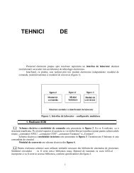
Part B – Demodulating an FSK signal using filtering and an envelope detectorAs FSK is really just FM (with a digital message instead of speech or music), it can berecovered using any of the FM demodulation schemes. However, as the FSK signal switchesback and forth between just two frequencies we can use a method of demodulating it thatcannot be used to demodulate speech-encoded FM signals. The next part of the experimentlets you do this.20. Increase the Function Generator’s output frequency to 25kHz.21. Locate the Tuneable Low-pass Filter module on the DATEx SFP and turn its soft Cut-off<strong>Frequency</strong> Adjust control fully clockwise.22. Turn the Tuneable Low-pass Filter module’s soft Gain control fully clockwise.23. Modify the set-up as shown in Figure 4 below.Note: Remember that the dotted lines show leads already in place.MASTERSIGNALSSEQUENCEGENERATOROLINECODEFUNCTIONGENERATORTUNEABLELPFUTILITIESCOMPARATORREF100kHzSINE100kHzCOS100kHzDIGITAL8kHzDIGITAL2kHzDIGITAL2kHzSINE1OO NRZ-LSYNCO1 Bi-O1O RZ-AMI11 NRZ-MCLKSPEECHGN DGN DXYANALOG I/ OACH1ACH0VARIABLE DC+DAC1DAC0INf CGAINf C x10 0OUTIN OUTRECTIFIERDIODE & RC LPFRC LPFSCOPECH ACH BTRIGGERFigure 4The FSK generation and demodulation parts of the set-up can be represented by the blockdiagram in Figure 5 on the next page. The Tuneable Low-pass Filter module is used to pick outone of the FSK signal’s two sinewaves and the DIODE and RC LPF on the Utilities module formthe envelope detector to complete the FSK signal’s demodulation.<strong>Experiment</strong> <strong>18</strong> – <strong>Frequency</strong> <strong>Shift</strong> <strong>Keying</strong> © 2007 Emona Instruments <strong>18</strong>-7
To Ch.ATuneableLow-pass FilterUtilitiesmoduleDigitalsignalEnvelopedetectorDemodulatedFSK signal25kHzTo Ch.BFSK generationFSK demodulationFigure 524. Compare the digital signal and the filter’s output.Question 4Which of the FSK signal’s two sinewaves is the filter letting through?Question 5What does the filtered FSK signal now look like?Ask the instructor to checkyour work before continuing.<strong>18</strong>-8© 2007 Emona Instruments <strong>Experiment</strong> <strong>18</strong> – <strong>Frequency</strong> <strong>Shift</strong> <strong>Keying</strong>
25. Modify the set-up by connecting the scope’s Channel B input to the envelope detector’soutput as shown in Figure 6 below.MASTERSIGNALSSEQUENCEGENERATOROLINECODEFUNCTIONGENERATORTUNEABLELPFUTILITIESCOMPARATORREF100kHzSINE100kHzCOS100kHzDIGITAL8kHzDIGITAL2kHzDIGITAL2kHzSINE1OO NRZ-LSYNCO1 Bi-O1O RZ-AMI11 NRZ-MCLKSPEECHGNDGNDXYANALOG I/ OACH1ACH0VARIABLE DC+DAC1DAC0INf CGAINf C x10 0OUTIN OUTRECTIFIERDIODE & RC LPFRC LPFSCOPECH ACH BTRIGGERFigure 626. Compare the original digital signal with the recovered digital signal.Question 6What can be used to “clean-up” the recovered digital signal?Ask the instructor to checkyour work before continuing.<strong>Experiment</strong> <strong>18</strong> – <strong>Frequency</strong> <strong>Shift</strong> <strong>Keying</strong> © 2007 Emona Instruments <strong>18</strong>-9
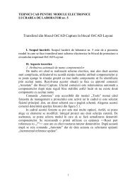
Part C – Restoring the recovered data using a comparator<strong>Experiment</strong> 16 shows that the comparator is a useful circuit for restoring distorted digitalsignals. The next part of the experiment lets you use a comparator to clean-up thedemodulated FSK signal.27. Slide the NI ELVIS Variable Power Supplies’ positive output Control Mode switch so thatit’s no-longer in the Manual position.28. Launch the Variable Power Supplies VI.29. Set the Variable Power Supplies’ positive output to 0V by pressing its RESET button.30. Modify the set-up as shown in Figure 7 below.MASTERSIGNALSSEQUENCEGENERATOROLINECODEFUNCTIONGENERATORTUNEABLELPFUTILITIESCOMPARATORREF100kHzSINE100kHzCOS100kHzDIGITAL8kHzDIGITAL2kHzDIGITAL2kHzSINE1OO NRZ-LSYNCO1 Bi-O1O RZ-AMI11 NRZ-MCLKSPEECHGNDGNDXYANALOG I/ OACH1ACH0VARIABLE DC+DAC1DAC0INf CGAINf C x10 0OUTIN OUTRECTIFIERDIODE & RC LPFRC LPFSCOPECH ACH BTRIGGERFigure 7<strong>18</strong>-10© 2007 Emona Instruments <strong>Experiment</strong> <strong>18</strong> – <strong>Frequency</strong> <strong>Shift</strong> <strong>Keying</strong>
The FSK generation, demodulation and digital signal restoration parts of the set-up can berepresented by the block diagram in Figure 8 below.To Ch.BDigitalsignal25kHzEnvelopedetectorINREFRestoreddigital signalTo Ch.BFSK generationFSK demodulationRestorationFigure 831. Compare the signals. If they’re not the same, adjust the Variable Power Supplies positiveoutput soft Voltage control until they are.Question 7How does the comparator turn the slow rising voltages of the recovered digital signalinto sharp transitions?Ask the instructor to checkyour work before finishing.<strong>Experiment</strong> <strong>18</strong> – <strong>Frequency</strong> <strong>Shift</strong> <strong>Keying</strong> © 2007 Emona Instruments <strong>18</strong>-11