Chapter 30 - Magnetic Induction - FSU Physics Department
Chapter 30 - Magnetic Induction - FSU Physics Department
Chapter 30 - Magnetic Induction - FSU Physics Department
- No tags were found...

You also want an ePaper? Increase the reach of your titles
YUMPU automatically turns print PDFs into web optimized ePapers that Google loves.
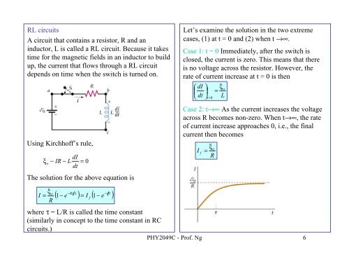
RL circuitsA circuit that contains a resistor, R and aninductor, L is called a RL circuit. Because it takestime for the magnetic fields in an inductor to buildup, the current that flows through a RL circuitdepends on time when the switch is turned on.Using Kirchhoff’s rule,ξ odI− IR − Ldt= 0The solution for the above equation isLet’s examine the solution in the two extremecases, (1) at t = 0 and (2) when t →∞.Case 1: t = 0 Immediately, after the switch isclosed, the current is zero. This means that thereis no voltage across the resistor. However, therate of current increase at t = 0 is then⎛ dI⎜⎝ dtIf⎞⎟⎠t=0ξo=Rξo=LCase 2: t→∞ As the current increases the voltageacross R becomes non-zero. When t→∞, the rateof current increase approaches 0, i.e., the finalcurrent then becomes−RtL−tτ( 1−e ) = I ( − e )ξoI =f1Rwhere τ = L/R is called the time constant(similarly in concept to the time constant in RCcircuits.)PHY2049C - Prof. Ng 6