Chapter 30 - Magnetic Induction - FSU Physics Department
Chapter 30 - Magnetic Induction - FSU Physics Department
Chapter 30 - Magnetic Induction - FSU Physics Department
- No tags were found...

Create successful ePaper yourself
Turn your PDF publications into a flip-book with our unique Google optimized e-Paper software.
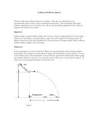
<strong>Chapter</strong> <strong>30</strong> - <strong>Magnetic</strong> <strong>Induction</strong>A changing magnetic field induces an electric For a loop whose normal is at an angle with B,current in a wire. Called magnetic induction, theφ m = BA cos θbasis principle of electric power.and for a coil containing N loops, the flux isThe generation of electricity is governed by theφ m = NBA cos θFaraday’s law of induction.Induced emf and Faraday’s law<strong>Magnetic</strong> fluxExperimentally observed that the emf produced isDefined in the same way as electric fluxproportional to the rate of changing flux.<strong>Magnetic</strong> flux can be changed in many ways,e.g., changing strength of B, area, angle betweenthe normal and B, and so on.<strong>Magnetic</strong>flux isincreasingrφm= ∫ B ⋅ndAˆ = ∫ BndAUnit is weber (Wb),since B isss1 Wb = 1 T⋅m 2 increasing.PHY2049C - Prof. Ng 1
Induced emf produced by a changing flux isr r dφmξ = ∫ E ⋅dl= −cFaraday’s lawdtThe integral of E over a closed loop is the emf (orvoltage) by definition of electric potential (<strong>Chapter</strong>24).PHY2049C - Prof. Ng 2
Lenz’s lawThe negative sign in Faraday’s law tells us thedirection of the induced current (or polarity of theinduced emf). Lenz’s law states:The flux produced by the induced current whichresults from the induced emf, opposes the originalchange in flux.The underlying principle of Lenz’s law is the lawof conservation of energy.Step-by-step instructions for using Lenz's law -used to determine the direction of the(conventional) induced current in a loop.Need the following:(i) a loop(ii) (an external) magnetic field inside loop or afield that is switched on or off.1. First determine whether the magnetic flux (=BA cos θ) inside loop is decreasing, increasing orunchanged.2. a. If flux is decreasing then induced magneticfield points in the same direction as the externalfield.b. If flux is increasing then induced magneticfield points in the opposite direction as theexternal field.c. If flux is not changing, then there is no inducedcurrent.3. From the induced magnetic field use RH rule(see Fig 29-14 a) to find the direction of thecurrent.PHY2049C - Prof. Ng 3
Motional emfIt is not necessary for a complete circuit for themotional emf to form. A metal bar movingthrough a magnetic field will have a voltageacross the ends.Inducedvoltage isV = BlvFlux enclosed by the rectangle is φ m = BA = Blx.As the rod of length l moves to the right, the rateof change of flux isd φ dxξ = m = Bl = Blvdt dtThe induced voltage is proportional to the speed atwhich the rod sweeps the magnetic field. Thedirection of current flow is governed by Lenz’slaw.NASA tethered experimentThe wire sweepsthe earth’smagnetic fieldproducing avoltage.PHY2049C - Prof. Ng 4
InductanceA coil that carries a current Iproduces a magnetic field that isproportional to the current. Theflux through the coil is then alsoproportional to I. Theproportionality constant is calledself-inductance, L, i.e.,φ = LISince the induced voltage is equal to the rate ofchange of the flux, the self-induced voltage isd mφξ = −dt= − LdIdtA coil with many turns or a solenoid has a largeself-inductance. The device is called an inductor,L and is represented on circuit diagrams byUnits for L is Henry (H). 1 H = 1 T⋅m 2 /A<strong>Magnetic</strong> energyRecall that a capacitor stores energy in the electricfield between the capacitor. In a similar, inductorscan store energy in its magnetic fields.The energy stored in an inductor with current I isUm =121 LI2QC2U c=2Compared to energy stored in a capacitorPHY2049C - Prof. Ng 5
RL circuitsA circuit that contains a resistor, R and aninductor, L is called a RL circuit. Because it takestime for the magnetic fields in an inductor to buildup, the current that flows through a RL circuitdepends on time when the switch is turned on.Using Kirchhoff’s rule,ξ odI− IR − Ldt= 0The solution for the above equation isLet’s examine the solution in the two extremecases, (1) at t = 0 and (2) when t →∞.Case 1: t = 0 Immediately, after the switch isclosed, the current is zero. This means that thereis no voltage across the resistor. However, therate of current increase at t = 0 is then⎛ dI⎜⎝ dtIf⎞⎟⎠t=0ξo=Rξo=LCase 2: t→∞ As the current increases the voltageacross R becomes non-zero. When t→∞, the rateof current increase approaches 0, i.e., the finalcurrent then becomes−RtL−tτ( 1−e ) = I ( − e )ξoI =f1Rwhere τ = L/R is called the time constant(similarly in concept to the time constant in RCcircuits.)PHY2049C - Prof. Ng 6
The previous circuit gives the case when voltageis applied across a R and an inductor. It is possibleto have a steady current flowing in the circuit andthen remove the battery from the circuit.The current as a function of time is thenI = I oe−tτPHY2049C - Prof. Ng 7