Sensors and systems for combustion technology System ... - lamtec
Sensors and systems for combustion technology System ... - lamtec Sensors and systems for combustion technology System ... - lamtec
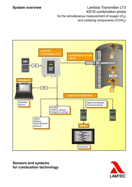
System overviewLambda Transmitter LT3KS1D combination probefor the simultaneous measurement of oxygen (O 2 )and oxidising components (CO/H 2 )LambdaTransmitter LT3Combination probeKS1D3 5 7 9LSB2 4 6 8NotebookO CO/H 2 2USBLAMTEC SYSTEM BUSOperationserviceto furtherLAMTEC devicesETAMATIC / BT300Digital and analogueinputs and outputsOption:ModbusPROFIBUS DPEthernetWriterRecordingSensors and systemsfor combustion technology
- Page 2 and 3: Theoretical foundations of the KS1D
- Page 4: Features of LT3 KS1D measuring syst
<strong>System</strong> overviewLambda Transmitter LT3KS1D combination probe<strong>for</strong> the simultaneous measurement of oxygen (O 2 )<strong>and</strong> oxidising components (CO/H 2 )LambdaTransmitter LT3Combination probeKS1D3 5 7 9LSB2 4 6 8NotebookO CO/H 2 2USBLAMTEC SYSTEM BUSOperationserviceto furtherLAMTEC devicesETAMATIC / BT300Digital <strong>and</strong> analogueinputs <strong>and</strong> outputsOption:ModbusPROFIBUS DPEthernetWriterRecording<strong>Sensors</strong> <strong>and</strong> <strong>systems</strong><strong>for</strong> <strong>combustion</strong> <strong>technology</strong>
Theoretical foundations of the KS1D measuringprincipleThe basis of the KS1D combination probe is a heatedelectrochemical measuring cell made of zirconiumdioxide ceramic.It has 3 electrodes:• O 2 -sensitive platinum electrode• CO/H 2 -sensitive electrode made from a platinum /gold alloy• Platinum reference electrodeSupplying the external electrode with a sample gas <strong>and</strong>the internal electrode with a reference gas of familiar O 2concentration, e.g. air (20.96 %O 2 ), with a continuousconstant temperature, results in the logarithmicassociation between the probe voltage U <strong>and</strong> the oxygenconcentration on the sample gas, as shown below.1 2 34U S5 6 7Fig. 1 Schematic structure of the KS1D combination probe1 Gas inlet2 Protective coat3 Heating element4 Working electrode (Pt/Au)5 Zirconium dioxide ceramic6 Reference electrode7 HousingThe O 2 measuring cell works as an electrochemicalconcentration change <strong>and</strong> generates a direct voltagewhich is dependent on the absolute temperature T <strong>and</strong>the logarithm of the O 2 concentration ratio or the O 2partial pressure ratio on the reference <strong>and</strong> O 2 externalelectrode.U HFig. 3 Sensor characteristic U = f (O 2 )Probe principle - CO/H 2 -sensitive electrodeCombustible components will be absorbed like oxygenmolecules on the electrode <strong>and</strong> diffuse to the "threephaseboundary", <strong>for</strong>med by sample gas, electrode <strong>and</strong>zirconium dioxide.Alongside Nernst voltage U O2 which is determined by theoxygen content, the combustible components in thesample gas generate an auxiliary direct voltage U CO/H2 .The sensor voltage is the total of the two voltagesU S = U O2 + U CO/H2 (see fig. 3).Even with low concentrations of oxidable gases, like H 2or CO, the mixed potential is considerably greater thanthat of the O 2 signal.The <strong>for</strong>mation of the mixed potential takes place veryquickly, t 60 -times below 2 sec. have been achieved.CO US (mV)Sensor characteristic(measured)Electrical equivalent circuit diagramNernst characteristic(calculated)U H13V AC/DCU SO U2 SCO/H 2Fig. 2 Electrical equivalent circuit diagramincomplete<strong>combustion</strong>complete<strong>combustion</strong>Fig. 4 Sensor characteristicO (%) 2
Lambda Transmitter LT3Microprocessor-based measuring transducer withdiagnostic functions.Fig. 5 Lambda Transmitter LT3The temperature of the KS1D flue gas probe is controlleddepending on the internal resistance of the sensor. TheKS1D combination probe is permanently monitored <strong>for</strong>failures or missing connections. Malfunctions aredetected by the electronics <strong>and</strong> lead to a fault or warningmessage.LT3 display <strong>and</strong> operating unitA programming unit, which is connected via the LAMTECSYSTEM BUS or is already integrated in the device, isused to display <strong>and</strong> operate the LT3.• External programming unit, connection via 5-pin M12plug-in connector• Internal programming unit, built in to the doorFig. 7 LSB modules with 4 analogue outputs, type 663 R 4025(voltage) / 663 R 4029 (current)Several modules can be connected using a strappingplug:• LSB modules with 4 analogue outputs (voltage)• LSB modules with 4 analogue outputs (current)• LSB modules with 4 analogue inputs (voltage /current)• LSB modules with 4 digital outputs• LSB modules with 4 digital inputsKS1D combination probe, type 656 R 2000132Fig. 6 Programming unitLSB modulesLSB modules are external/internal input/output modulesthat are connected with the LT3 via the LAMTECSYSTEM BUS (LSB). They enable a needs-based, userspecificdesign of the LT3 <strong>and</strong> can be retrofitted at anytime. The distance from the LT3 can be up to 500 m. Thisallows a decentralised location <strong>and</strong> reduces the amountof wiring.Fig. 8 KS1D combination probe1 KS1D combination probe without housing;St<strong>and</strong>ard cable length 2 m, Teflon, with connectorplug2 Gas extraction device (GED), type 655 R1001...1004 (150...1000 mm)3 KS1D combination probe in housing(incl. Item 1, 2 + 3)
Features of LT3 KS1D measuring system• Direct (in situ) measurement of oxygen (O 2 ) <strong>and</strong> oxidable exhaust gas components (CO/H 2 ) in gases, preferablyin <strong>combustion</strong> plants, in the superstoichiometric area (λ>1).• O 2 range of measuring: 0 to 21 vol.%• CO e range of measuring: 0...10.000 ppm• Independent of false air (CO e )• No gas preparation required, measurement directly in the moist flue gas• Setting time to 60 % value (T60) < 10 seconds: CO e < 2 seconds• Low heating power with LT3 15..0.18 Watt, depending on the exhaust gas temperature• Low-maintenance• Type 656 R 2000 in housing <strong>for</strong> exhaust gas temperatures < 300°C• 5-wire Teflon cable with circular connector, length 2 m• Type 656 R 2000 in housing <strong>for</strong> exhaust gas temperatures


