

Double-Dry-nOn-cooled-Probe - Webshop, Gas Analysis Technology
Double-Dry-nOn-cooled-Probe - Webshop, Gas Analysis Technology
Double-Dry-nOn-cooled-Probe - Webshop, Gas Analysis Technology
- No tags were found...

You also want an ePaper? Increase the reach of your titles
YUMPU automatically turns print PDFs into web optimized ePapers that Google loves.
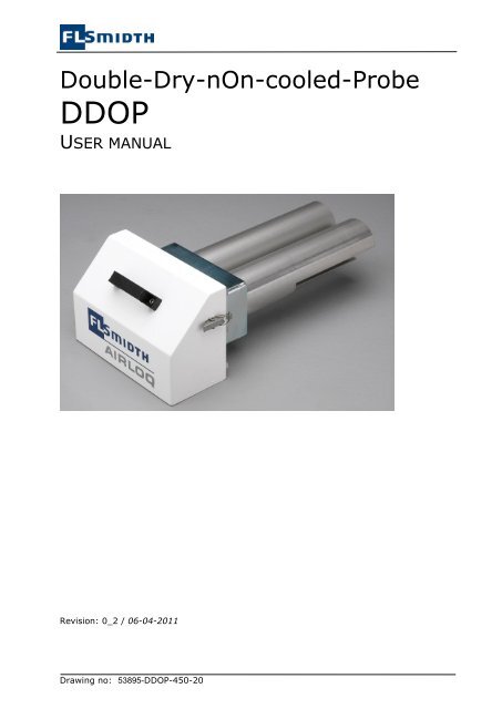
<strong>Double</strong>-<strong>Dry</strong>-<strong>nOn</strong>-<strong>cooled</strong>-<strong>Probe</strong>DDOPUSER MANUALRevision: 0_2 / 06-04-2011Drawing no: 53895-DDOP-450-20
Unit Operation InstructionDDOP <strong>Probe</strong>TABLE OF CONTENTSDDOP ....................................................................................................................... 11.1 APPENDIX ....................................................................................................... 21.2 SERIAL NUMBERS .............................................................................................. 22 PREFACE .............................................................................................................. 32.1 DOCUMENT MAP ............................................................................................... 32.2 DEFINITIONS AND TERMS .................................................................................... 32.2.1 GENERAL .................................................................................................. 32.2.2 UNITS AND CONVERSION FACTORS.................................................................... 32.2.3 DDOP PROBE ............................................................................................ 42.3 HOW TO READ THIS MANUAL ................................................................................. 42.4 WARNING ....................................................................................................... 42.4.1 WARNING – HAZARDOUS VOLTAGES! ................................................................. 42.4.2 WARNING – TOXIC, EXPLOSIVE GASES ............................................................... 52.4.3 WARNING - ACIDS ....................................................................................... 52.4.4 WARNING - BURNS ...................................................................................... 52.4.5 WARNING - PRESSUREE ................................................................................. 52.4.6 WARNING – MOVING MACHINERY ...................................................................... 53 TECHNICAL INFORMATION DDOP PROBE ......................................................................... 63.1 PHYSICAL DISTANCE BETWEEN EQUIPMENT ................................................................. 63.2 GENERAL INFORMATION DDOP PROBE ..................................................................... 74 INSTALLATION OF PROBE ........................................................................................... 84.1 BEFORE INSTALLATION ........................................................................................ 84.1.1 TRANSPORT............................................................................................... 84.1.2 UNPACKING............................................................................................... 84.2 INSTALLING THE PROBE ....................................................................................... 84.3 FLANGE CONNECTION TO PROCESS .......................................................................... 84.4 CONNECTION OF HOSES ...................................................................................... 84.4.1 CLEANING AIR HOSES ................................................................................... 84.4.2 HEATED SAMPLE LINES .................................................................................. 85 SAFETY INSTRUCTION ............................................................................................... 96 FUNCTION DESCRIPTION OF PROBE ............................................................................... 106.1 UNIT OVERVIEW .............................................................................................. 106.2 PARTS .......................................................................................................... 106.3 FUNCTION DESCRIPTION PROBE ............................................................................ 106.4 COMMISSIONING OF PROBE ................................................................................. 106.5 DISMOUNTING PROBE ........................................................................................ 107 PROBE CLEANING BOX ............................................................................................. 117.1 INSTALLATION ................................................................................................. 117.1.1 LOCATION OF GMU ................................................................................... 117.1.2 AIR SUPPLY............................................................................................. 117.1.3 CABLING BETWEEN GAS MONITORING UNIT AND OTHER EQUIPMENT ........................... 118 MAINTENANCE ....................................................................................................... 118.1 GENERAL ....................................................................................................... 118.2 SPARE PARTS .................................................................................................. 118.3 MAINTENANCE PROBE ........................................................................................ 118.3.1 PREPARE PROBE FOR MAINTENANCE ................................................................ 128.3.2 MAINTENANCE FILTER OF PROBE .................................................................... 12Drawing no: 53895-DDOP-450-20 Page 1 of 14
Unit Operation InstructionDDOP <strong>Probe</strong>8.4 MAINTENANCE PROGRAM FOR THE PROBE ................................................................. 129 TROUBLE SHOOTING ................................................................................................ 1310 CONTACT INFO ...................................................................................................... 1311 DOCUMENT REVISION .............................................................................................. 131.1 APPENDIX(Appendix is found directly after this operating instruction)• Drawings according to “Document list: Drawings”• Part list1.2 SERIAL NUMBERSThis manual is specifically related to the following unit serial numbersThis manual covers all serial numbers from49393-01 and forwardThe serial number follows the terms like: 5xxxx-yy where 5xxxx indicates serial lot number. The “yy”is a unique unit number(Documents revision history versus serial numbers is found in section 10)The serial number is tagged on each unit with a stainless steel plate on front of frame orsimilar.Drawing no: 53895-DDOP-450-20 Page 2 of 14
Unit Operation InstructionDDOP <strong>Probe</strong>2 PREFACEThis operating instruction is called a unit manual. The operating instruction covers only thisparticnular unit with respect to technical data, installation, use etc. This specific unit is apart of a complete system. Control and interaction in the specific system may varyaccording to system demands.The SDSP <strong>Probe</strong> is to be used with FLSmidth Airloq analysis system. The <strong>Probe</strong> comprises aflange, piping, Filter, connectors among others.The system interaction with the SDSP-<strong>Probe</strong> is described in the system manual. Thedocument overview is to be found in section 2.1.The whole analysis system is to be operated and maintained as described in the systemmanual. If not, the efficiency and lifetime of the system will be reduced. An alarm mustalways be corrected at once. Qualified and trained personnel must perform themaintenance.2.1 DOCUMENT MAPThis manual is to be considered as part of the complete system documentation. A completeset of system documentation for an FLSmidth Airloq A/S gas analysis system may comprise:• User manuals (Binder) (all project specific drawings, list etc.) includingo System datasheets covering project specific data.o System operation instructionso Unit operating instructions (this document among others)o Drawings, lists etc.• Data sheets (Binder)o Sub supplier’s manuals and datasheets2.2 DEFINITIONS AND TERMS2.2.1 GENERALSystem (analysis system)System manualSystem datasheetUnit manualGMUCUBETrained/qualified PersonnelThe complete analysis system which includes this unit amongothersThe manual covering system function and interaction with thisunitOverall system data where all technical data and units areidentifiedAn operating instruction for a specific unit (Part of completesystem. E.g. for a <strong>Probe</strong>)<strong>Gas</strong> Monitoring Unit: Cabinet or housing comprising analysisparts, power distribution and control.FLSmidth Airloq A/S analysis housing insulated, heated, <strong>cooled</strong>and with GMU installed.Indicates personnel that is not only certified to work on theplant according to all local and national regulations, butpersonnel who also has specific training from e.g. FLSmidthAirloq in use and maintenance of gas analysis systems.2.2.2 UNITS AND CONVERSION FACTORSAll units in FLSmidth Airloq documentation are SI-units except from:Drawing no: 53895-DDOP-450-20 Page 3 of 14
Unit Operation InstructionDDOP <strong>Probe</strong>Pressure:Temperature:Bar°C (degrees Celsius)For general use the following approximations can be used for conversion:Length: mm to inch factor 0,04Pressure: Bar to PSI (US) factor 14,5Temperature: °C to °F °F = °C × 1.8 + 322.2.3 DDOP PROBEDDOP<strong>Probe</strong>BBFilter<strong>Double</strong>-<strong>Dry</strong>-<strong>nOn</strong>-cOoled-<strong>Probe</strong>Extracts sample gas from a specific point in process.Blow-back cleaning air for filter cleaning.Filters sample gas from dust particles to protect the system.2.3 HOW TO READ THIS MANUALRead the instructions in this manual carefully before installing the system.FLSmidth Airloq A/S cannot accept any liability for damages due to nonobservanceof this manual.Sign:Before doing anything to the system, read warnings in section 2.4.This manual must be used in conjunction with the appendix. The document map in section2.1 shows an overview of the complete gas analysis system. This document covers theSDSP <strong>Probe</strong> only. For e.g. electrical wiring, the reader must use the appendix “Circuitdiagram”. All issues related to system performance must be found in the system manual.No part of this manual may be reproduced or transmitted in any form or by any means,electronic or printed, without the prior written permission of FLSmidth Airloq A/S. If thismanual is translated, the English version is to be considered as the original one.2.4 WARNING2.4.1 WARNING – HAZARDOUS VOLTAGES!Sign:All electrical installations must be in accordance with national and local regulations, andqualified personnel who are aware of these regulations must perform the electricalinstallation.Voltage must not be applied to the system until all electrical connections have been madeand checked and then only by qualified personnel who are aware of the risks involved.Any disconnection of the earthed conductor inside or outside the device or the release of theearthed conductor connection can make the device hazardous to life. Deliberatedisconnection is inadmissible/prohibited.All connections must be made in accordance with the drawings in this manual.Drawing no: 53895-DDOP-450-20 Page 4 of 14
Unit Operation InstructionDDOP <strong>Probe</strong>2.4.2 WARNING – TOXIC, EXPLOSIVE GASESSign:Be sure to observe the safety regulations for the respective gases (sample gas and testgases/span gases) and test gas cylinders! The gas outlet should be led to ambient air toavoid danger to operators.Inflammable or explosive gas mixtures must not be introduced into the analysis systemunless the system is designed for the application.To avoid danger to operators by explosive, toxic or unhealthy gas components, flush thegas lines with ambient air or nitrogen before cleaning or exchange parts of the gas paths.2.4.3 WARNING - ACIDSSign:To avoid danger to operators by acid droplets build up in gas lines, first flush the gas linesbefore cleaning or exchange parts of the gas paths.Always use skin and eye protection before cleaning or exchanging parts of the gas pathsincluding condensate trap.2.4.4 WARNING - BURNSSign:To avoid the danger of operators getting burned due to high temperatures of probe andother components, the demands of occupational health regulations should be followed.Always plug the hole to the process when the probe is removed from the flange. The plugmust be secured with the lock pin.2.4.5 WARNING - PRESSUREESign:To avoid danger to operator the hoses must be without pressure before dismounting of anyconnections or hoses.2.4.6 WARNING – MOVING MACHINERYSign:Do not remove covers from Extraction Device with compressed air pressure to ExtractionDevice.Drawing no: 53895-DDOP-450-20 Page 5 of 14
Unit Operation InstructionDDOP <strong>Probe</strong>3 TECHNICAL INFORMATION DDOP PROBEDimensions:Total, LxWxHSample Filter:MaterialFilter size640x330x220mmAISI 316L20µm ,102xØ50/40Process conditions:Available length for insertion in process400mmTemperature Max. 400°CDust load Max. 200 g/m 3Weight:Weight, dry:26 kgTemperatures:Ambient temperature: -10°C to 55°C 1Storage temperature: -15°C to 55°CEquipment must be protected against heatradiationConnections:Sample line connection:6 mm stainless steel SwagelokBlow Back hoses10 mm stainless steel SwagelokHose clampsSpecified according to actual sample gas hosediameter.Flange for mounting probeSee Drawing “DDOP <strong>Probe</strong>”Flange is supplied by FLSmidth AirloqCompressed air:Pressure:600 kPaRange 550-750 kPaConsumption:1 Nm3/h at 600 kPaQuality: 3-3-3 according to ISO 8573-1Maximum 5 mm (size) 5 mg/m3 particlesMinimum -20° water pressure dew point**Pressure dew point must be minimum -10°Cbelow minimum ambient temperature at anytime.Maximum 1 mg/m3 oil3.1 PHYSICAL DISTANCE BETWEEN EQUIPMENTThis information is covered by the system manual.1 <strong>Probe</strong> must be protected to prevent condensation and freezing.Drawing no: 53895-DDOP-450-20 Page 6 of 14
Unit Operation InstructionDDOP <strong>Probe</strong>3.2 GENERAL INFORMATION DDOP PROBEThe <strong>Double</strong>-<strong>Dry</strong>-<strong>nOn</strong>-cOoled-<strong>Probe</strong> (DDOP) is made of stainless steel, enabling it towithstand temperatures of up to 400°C.The DDOP probe is special designed for use after the pre-heater in cement plants. Theprobe is normally installed in the down comer pipe coming from the top of the pre-heater.The probe is a double probe thus it can be used for continuous measuring.A stainless steel filter is mounted in the probe, inside the process, the purpose of the filteris to avoid dust particles to be transported into the sample lines.Drawing no: 53895-DDOP-450-20 Page 7 of 14
Unit Operation InstructionDDOP <strong>Probe</strong>4 INSTALLATION OF PROBESee layout drawing “System View”4.1 BEFORE INSTALLATION4.1.1 TRANSPORTAll transport must be carried out according to local regulations. Transport may be doneeither with equipment in transport box or unpacked. When equipment is still in a box, itmay be moved by standard fork lift.When unpacked, the <strong>Probe</strong> is easily handled manually.It is highly recommended to unpack equipment as close as possible to installation point toprotect against damage during storage and transport.4.1.2 UNPACKINGBefore installation equipment must be unpacked, the wood box must be opened with acrowbar, or e.g. a circular saw (buzz saw) may be used to open the seaworthy box. The sawmust be carefully adjusted to a cutting dept of max. 2 mm though wood panels to avoiddamage of equipment.4.2 INSTALLING THE PROBEThe probe is bolted to the supplied flange, se layout drawings “DDOP: <strong>Probe</strong>”, “DDOP:System view”1. The measuring point must be located in a place where the gas is homogenous andrepresentative for the process.2. As rule of thumb there must not be any obstacles 5 x channel diameter before and 2 xchannel diameter after probe location.3. The probe must be positioned thus the filters are “protected” against the gas flow. Thisis to avoid directly downstroke of dust on the filter.4.3 FLANGE CONNECTION TO PROCESSThe flange is welded to the process4.4 CONNECTION OF HOSESAll hoses must be protected against environment and damage. Hoses must be secured toe.g cable ladders.4.4.1 CLEANING AIR HOSESThe probe is connected to the <strong>Probe</strong> Cleaning Panel using the hoses supplied. Position thehoses thus bends are avoided. Take care to leave space to withdraw the probe from theprocess without disconnecting any hose.Connect the cleaning air hoses according to the following tableFrom <strong>Probe</strong>To PCP10 mm Swagelok fitting on Line 1 10 mm bulkhead labelled “BB1”10 mm Swagelok fitting on Line 2 10 mm bulkhead labelled “BB2”4.4.2 HEATED SAMPLE LINESThe probe is connected to the GMU using the supplied heated sample lines E1 and E2. Inorder to avoid pressure drops and condensate traps the hose must be installed thus bendsDrawing no: 53895-DDOP-450-20 Page 8 of 14
Unit Operation InstructionDDOP <strong>Probe</strong>are avoided.Connect the heated sample lines according to following tableFrom <strong>Probe</strong>To GMU6 mm Swagelok fitting on Line 1 Through cable gland labelled “line 1” to 6mmfitting on gas cooler stage E1.1_L16 mm Swagelok fitting on Line 2 Through cable gland labelled “line 2” to 6mmfitting on gas cooler stage E1.1_L2In order to avoid “cold spots” the sample lines must be additionally fixed to the Swagelokfitting by mean of the hose connector, see item W1-09 on drawing “DDOP probe”. The hoseconnector must be installed on the hose end before the 6mm cut-ring is tightened. After the6mm PTFE hose is connected the hose must be pushed to the fitting and the two screws onthe hose connector tightened. At last the hose clamp on the DDOP probe must be fastenedthus the sample hose is proper relieved.5 SAFETY INSTRUCTIONSafety procedure before work on <strong>Probe</strong>Issue:Procedure:Stop systemStop system according to the system manual.Test modeSet system is in test mode, and disables all alarms to CCSaccording to the system manual.Shut off power supplyShut off all electrical power sources from system GMUaccording to system manual.Shut off the air supplyClose main air valve air supply e.g. V2.3 on the Utillity Air.Blow down the pressure in air tanks. Install padlock orsimilar to secure valve.Perform work on <strong>Probe</strong>Remove covers etc. from unit.Drawing no: 53895-DDOP-450-20 Page 9 of 14
Unit Operation InstructionDDOP <strong>Probe</strong>6 FUNCTION DESCRIPTION OF PROBESee layout drawing “SDSP <strong>Probe</strong>”6.1 UNIT OVERVIEWHeat shieldWeld flangeFilters(Hidden)Sample and BBhoseconnecetionsPic 1 <strong>Probe</strong> parts overview<strong>Probe</strong>s Line 1and Line 2Sample hose clamps6.2 PARTSTag number Type FunctionW1 <strong>Probe</strong> <strong>Probe</strong> default tag numberDetailed view with subparts can be seen on drawing “DDOP <strong>Probe</strong>”6.3 FUNCTION DESCRIPTION PROBEThe purpose of the probe is to ensure that the gasses measured are representative for theprocess gas. The sample end of the probe is inserted into the process. The probe is a doubleprobe thus it can be used for continuous measuringThe probe is made of a stainless steel alloy, which has proven efficient for the application.6.4 COMMISSIONING OF PROBEAfter installation as described in section 4.2 and checking of all electrical and mechanicalinstallation, the <strong>Probe</strong> can be commissioned in conjunction with analysis system asdescribed in “System Manual” The <strong>Probe</strong> is not requiring any adjustments.· Check all bolts are tightened properly· Check sample hoses and blow back hoses are correct installed as described· Check the white insulating cover is correct installed.6.5 DISMOUNTING PROBETo dismount the probe, follow this procedure:Issue:Procedure:Set GMU in test modePut the system into TEST mode and stop the analysis, asdescribed in “System operation manual”Disconnecting all hosesDisconnect sample lineDismount the probeThe probe can now be dismounted from its flangeDrawing no: 53895-DDOP-450-20 Page 10 of 14
Unit Operation InstructionDDOP <strong>Probe</strong>7 PROBE CLEANING BOXDepending of the system configuration the DDOP probe is supplied with a <strong>Probe</strong> Cleaningbox (See system datasheet).The <strong>Probe</strong> Cleaning Box comprises of cleaning valves and terminals for probe filter cleaning.For each probe filter is a valve that connects by the flexible steel bread hoses to the probefilter tubes. The valves is controlled by the system controller7.1 INSTALLATION7.1.1 LOCATION OF GMUInstall the <strong>Probe</strong> Cleaning Box as close as possible to the probe. Make sure that probe canbe removed from process without disconnection of flexible hoses7.1.2 AIR SUPPLYThe <strong>Probe</strong> Cleaning Box is to be connected to the main air supply by a buffer air tank. Thetank should provide pressure control and air punch to ensure sufficient filter cleaning. TheFLS Utillity Air option is recommended.Connection from eg. Utillity Air to <strong>Probe</strong> Cleaning Box should be done in standard piping'sby the customer.Connect the air supply according to the installation drawings.7.1.3 CABLING BETWEEN GAS MONITORING UNIT AND OTHER EQUIPMENTCables must be connected according to section “Cable list” in this manual.8 MAINTENANCE8.1 GENERALThe analysis system must be maintained and checked daily, the following sections containsmaintenance sheets for each unitTo ensure optimal drift and highest possible run time, the equipment should be serviced byan authorised service engineer. The service interval can vary from 1-4 times pr. year.Please contact us at the email address or telephone mentioned below for:· Proposal for a specific service agreement for the present equipment, 24h or normalcontract· Preventive maintenance according to technical documentation· Technical support· Immediate service at breakdown8.2 SPARE PARTSWear parts and recommended spare parts are listed in a section of the parts list. To ensurethat the correct part is delivered when ordering spare parts, please provide FLSmidth Airloqwith the project number which is found on the “System Data Sheet” and the FLSmidth PartNo. (6 digit) or Parts Id / Int. No.8.3 MAINTENANCE PROBEDuring the first few weeks of operation it is important to check the system every day, inorder to get to know the system and the applications in which it is installed and perhaps doadjustments if any.Always keep equipment clean outside and inside. Do not use compressed air to cleancabinets inside.Drawing no: 53895-DDOP-450-20 Page 11 of 14
Unit Operation InstructionDDOP <strong>Probe</strong>NOTE warnings in section 2.48.3.1 PREPARE PROBE FOR MAINTENANCEIssue:Procedure:Stop system/Test mode For system control, see system manualShut off the air supply Close valve V2.3 on the PCPBlow downOpen V2.2 and blow down the air receiverCarry out maintenance As described belowClose drain Close valve V2.2Open air supplyOpen valve V2.3 on the PCPTest mode off / StartFor system control, see system manualsystem on8.3.2 MAINTENANCE FILTER OF PROBEClean filter monthly or when required.NOTE: The probe is very hot when it comes out of the process, take care.Follow the below:Issue:Dismount the sample line formprobeDismount filter from probeClean filterReassemble the probeProcedure:Undo the nut on Swagelok fittingUndo the boltsPull out the filter tubeUse compressed air in the Swagelok fittingUse compressed air on the outside of the filterPut filter back in probe and tighten the bolt. Remember supportfor heated hoseReconnect heated hose to Swagelok fitting8.4 MAINTENANCE PROGRAM FOR THE PROBERefer to section 8.3, to get instructions how to do the maintenance in the following table.Date /Initials Maintenance program D W M YHose connections:XMake visually leak check of flexible hosesClean filter element½Check Cleaning valves and perform service ifrequired (Leak test to be performed)3Drawing no: 53895-DDOP-450-20 Page 12 of 14
Unit Operation InstructionDDOP <strong>Probe</strong>9 TROUBLE SHOOTINGAlarms may vary according to implementation in the system.Fault Meaning Probable cause SolutionFilterbloggingLow sample gasflow due toblockage on filterelement10 CONTACT INFOCondensation on filterelement or fittingscollects dust particlesdue to low temperature1. Insolate probe andfittings to collectprocess heatFLSmidth A/S<strong>Gas</strong> <strong>Analysis</strong> <strong>Technology</strong>Klostermarken 6 · DK-9550 Mariager · DenmarkTel.: +45 7010 2277 · Fax: +45 7010 2288Main e-mail: flsairloq@flsairloq.comService e-mail: service@flsairloq.comCVR-No. DK 10 36 42 48www.flsairloq.com11 DOCUMENT REVISIONRev. Date Author Description Serial numberscovered0_2 06-04-2011 RBN <strong>Probe</strong> Cleaning Box 53895 and forward0_1 23-12-2008 RBN New doc. 49393 and forwardDrawing no: 53895-DDOP-450-20 Page 13 of 14
Document List:Unit ManualRevision List: Unit ManualCustomer Drawing No.:S-GENERI--1-000-50Rev. Date. Ini. Remarks0 27-08-09 RBN1 13-01-12 PQvPCP: P&I DiagramCustomer Drawing No.:S-GENERI--1-100-11ARev. Date. Ini. Remarks0 24-11-11 PQvDDOP: <strong>Probe</strong>Customer Drawing No.:S-GENERI--1-130-10Rev. Date. Ini. Remarks0 23-12-08 RBNPCP DDOP: Component LayoutCustomer Drawing No.:S-GENERI--1-170-30Rev. Date. Ini. Remarks0 24-11-11 PQvCable listCustomer Drawing No.:S-GENERI--1-310-10Rev. Date. Ini. Remarks0 24-11-11 PQvPart listCustomer Drawing No.:S-GENERI-49394-DDOP-300-10Rev. Date. Ini. Remarks0 27-08-09 RBNFLSmidth Airloq A/SKlostermarken 69550 MariagerTlf: +45 70102277FLS Airloq Project : Generic documentationProject No. : S-GENERI<strong>Analysis</strong> system : DDOP <strong>Probe</strong>Customer:End Customer:Rev. Date. Ini. Remarks.1 13-01-12 PQvDrawing number:S-GENERI--1-000-501 / 1The information transmitted by this document is the proprietary and confidential property of FLSmidth, and may not be duplicated, disclosed, or utilized without written consent from FLSmidth
A2.1DDOP PCPBB2BB1Y2.2Y2.1FLSmidth A/S<strong>Gas</strong> <strong>Analysis</strong> <strong>Technology</strong>Klostermarken 69550 Mariager, DenmarkProject / Plant name:- -Drawing title:PCP DDOP: P&I DiagramDrawing number (FLSmidth GAT):5xxxx-DDOP-x-100-11ADrawing number (Customer):Drawing scale: Drawing units: Revision: Initials: Date:Nonemm 0 PQv 24-11-11The information transmitted by this document is the proprietary and confidential property of FLSmidth, and may not be duplicated, disclosed, or utilized without written consent from FLSmidth
218W1-08326 635W1-04W1 W1-05 W1-06320397 95W1-03Line 1Line 2xxxxx-xxxxxxx-xxW1-07W1-10240210130W1-02W1-01W1-11W1-09FLSmidth Airloq A/SKlostermarken 6DK 9550 MariagerDenmarkProject / Plant name:- -Drawing title:DDOP: <strong>Probe</strong>Drawing number (FLS Airloq):49393-DDOP--130-10Drawing number (Customer):Drawing scale: Drawing units: Revision: Initials: Date:1:5mm 0 RBN 23-12-08The information transmitted by this document is the proprietary and confidential property of FLSmidth, and may not be duplicated, disclosed, or utilized without written consent from FLSmidth
1E81S81 7Y2.1 Y2.2BB1BB2- -PCP V2 Component Layout1123xx-DDOP-0-170-301:xmm 0 PQv 13-01-12The information transmitted by this document is the proprietary and confidential property of FLSmidth, and may not be duplicated, disclosed, or utilized without written consent from FLSmidth
Part list<strong>Gas</strong> Monitoring UnitPart ID Pcs. Part description Part No.RemarksFLS No ManufactorW1 1 <strong>Probe</strong>, DDOP GP-DDOP, 1162067 Complete probe, including weld flange 102675 FLSMIDTH AIRLOQSample probe.Part ID Pcs. Part description Part No.RemarksFLS No ManufactorBB1, BB2 2 Hose, SS braid, PTFE 3m, Ø3/8" P23/07-10-3000-11 D=Ø3/8", Con=10mm, l=3000mm101531 BSSPECIALSLANGERBB1, BB2 2 Sign, Ø27, "BB1" SS: 1mm104441 FLSMIDTH AIRLOQBB1, BB2 2 Sign, Ø27, "BB2" SS: 1mm104442 FLSMIDTH AIRLOQW1 1 <strong>Probe</strong>, DDOP GP-DDOP, 1162067 Complete probe, including weld flange 102675FLSMIDTH AIRLOQW1-01 2 Filter tube 1162060 102561 FLSMIDTH AIRLOQW1-02 2 Filter, Sika IS R20,102xØ50/40 6391110200003701 Filter probe, AISI 316L ,G3/8"100852GKN SINTER METALSFILTERS GMBHW1-03 2 <strong>Gas</strong>ket, filter tube 102 3903 Ø105, DN20 102569 FLSMIDTH AIRLOQW1-04 1 <strong>Gas</strong>ket, DDOP 102 3904 320x210x3102568FLSMIDTH AIRLOQW1-05 1 Flange, DDOP weld flange 1162062 102564 FLSMIDTH AIRLOQW1-06 1 Flange, DDOP, SS 1162063 102565 FLSMIDTH AIRLOQW1-07 1 Leak tool, DDOP 1162066 102567 FLSMIDTH AIRLOQW1-08 1 Shield, DDOP white w. logo 103731 FLSMIDTH AIRLOQFLSmidth Airloq A/SKlostermarken 69550 MariagerTlf: +45 70102277FLS Airloq Project : Generic documentationProject No. : S-GENERI<strong>Analysis</strong> system : DDOP <strong>Probe</strong>Customer:End Customer:Rev. Date. Ini. Remarks.0 27-08-09 RBNDrawing number:S-GENERI-49394-DDOP-300-101 / 3The information transmitted by this document is the proprietary and confidential property of FLSmidth, and may not be duplicated, disclosed, or utilized without written consent from FLSmidth
Part listSample probe.Part ID Pcs. Part description Part No.RemarksFLS No ManufactorW1-09 2 Hose connector, 16/10mm 1162091 For heated sample hose103595FLSMIDTH AIRLOQW1-10 2 Pipe section, Ø10x36 103800 FLSMIDTH AIRLOQW1-11 2 Angle, 10-10mm, SS SS-10M0-9 101823 SWAGELOK<strong>Probe</strong> Cleaning PanelPart ID Pcs. Part description Part No.RemarksFLS No Manufactor1E8 0 Heater, Cabinet, 130W SK 3107.000 VARENUMMER SPÆRRET104499 RITTAL1S8 0 Thermostate, 5-60°C SK 3110.000 100271 RITTALA2 1 Cabinet, 300*400*120(PCP DDOP) 1556.500 106378 RITTALA2 1 <strong>Probe</strong> Cleaning Panel, PCP PCP DDOP 106231 FLSMIDTH AIRLOQY2.1, Y2.2 2 Valve 2/2,1/2" NC 24VDC 204339 Atex Zone 2 dust105998BÜRKERT-CONTROMATICRecommended wear parts for 12 monthsPart ID Pcs. Part description Part No.RemarksFLS No ManufactorW1, DDOP 2 Filter, Sika IS R20,102xØ50/40 6391110200006601 Filter probe, AISI 316L ,G3/8"100852FLSMIDTH AIRLOQW1, DDOP 2 <strong>Gas</strong>ket, filter tube 102 3903 Ø105, DN20 102569 FLSMIDTH AIRLOQFLSmidth Airloq A/SKlostermarken 69550 MariagerTlf: +45 70102277FLS Airloq Project : Generic documentationProject No. : S-GENERI<strong>Analysis</strong> system : DDOP <strong>Probe</strong>Customer:End Customer:Rev. Date. Ini. Remarks.0 27-08-09 RBNDrawing number:S-GENERI-49394-DDOP-300-102 / 3The information transmitted by this document is the proprietary and confidential property of FLSmidth, and may not be duplicated, disclosed, or utilized without written consent from FLSmidth
Part listRecommended wear parts for 12 monthsPart ID Pcs. Part description Part No.RemarksFLS No ManufactorRecommended spare partsPart ID Pcs. Part description Part No.RemarksFLS No ManufactorA2, Y2.1, Y2.2 1 Valve 2/2,1/2" NC 24VDC 204339 Atex Zone 2 dust105998W1, BB1, BB2 1 Hose, SS braid, PTFE 3m, Ø3/8" P23-07-10-3000-11 D=Ø3/8", Con=10mm, l=3000mm101531W1, DDOP 1 <strong>Gas</strong>ket, DDOP 3mm 1023904 320x210x3mm102568BÜRKERT-CONTROMATICBSSPECIALSLANGERFLSMIDTH AIRLOQFLSmidth Airloq A/SKlostermarken 69550 MariagerTlf: +45 70102277FLS Airloq Project : Generic documentationProject No. : S-GENERI<strong>Analysis</strong> system : DDOP <strong>Probe</strong>Customer:End Customer:Rev. Date. Ini. Remarks.0 27-08-09 RBNDrawing number:S-GENERI-49394-DDOP-300-103 / 3The information transmitted by this document is the proprietary and confidential property of FLSmidth, and may not be duplicated, disclosed, or utilized without written consent from FLSmidth


