Advance Modeling of a Skid-Steering Mobile Robot for Remote ...
Advance Modeling of a Skid-Steering Mobile Robot for Remote ...
Advance Modeling of a Skid-Steering Mobile Robot for Remote ...
- No tags were found...

Create successful ePaper yourself
Turn your PDF publications into a flip-book with our unique Google optimized e-Paper software.
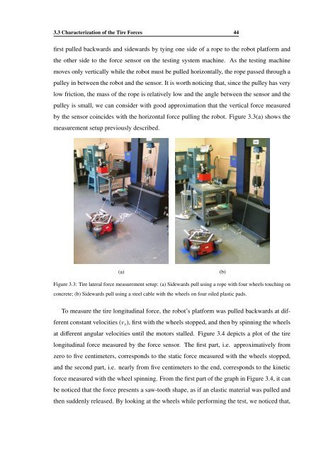
3.3 Characterization <strong>of</strong> the Tire Forces 44first pulled backwards and sidewards by tying one side <strong>of</strong> a rope to the robot plat<strong>for</strong>m andthe other side to the <strong>for</strong>ce sensor on the testing system machine. As the testing machinemoves only vertically while the robot must be pulled horizontally, the rope passed through apulley in between the robot and the sensor. It is worth noticing that, since the pulley has verylow friction, the mass <strong>of</strong> the rope is relatively low and the angle between the sensor and thepulley is small, we can consider with good approximation that the vertical <strong>for</strong>ce measuredby the sensor coincides with the horizontal <strong>for</strong>ce pulling the robot. Figure 3.3(a) shows themeasurement setup previously described.(a)(b)Figure 3.3: Tire lateral <strong>for</strong>ce measurement setup: (a) Sidewards pull using a rope with four wheels touching onconcrete; (b) Sidewards pull using a steel cable with the wheels on four oiled plastic pads.To measure the tire longitudinal <strong>for</strong>ce, the robot’s plat<strong>for</strong>m was pulled backwards at differentconstant velocities (v x ), first with the wheels stopped, and then by spinning the wheelsat different angular velocities until the motors stalled. Figure 3.4 depicts a plot <strong>of</strong> the tirelongitudinal <strong>for</strong>ce measured by the <strong>for</strong>ce sensor. The first part, i.e. approximatively fromzero to five centimeters, corresponds to the static <strong>for</strong>ce measured with the wheels stopped,and the second part, i.e. nearly from five centimeters to the end, corresponds to the kinetic<strong>for</strong>ce measured with the wheel spinning. From the first part <strong>of</strong> the graph in Figure 3.4, it canbe noticed that the <strong>for</strong>ce presents a saw-tooth shape, as if an elastic material was pulled andthen suddenly released. By looking at the wheels while per<strong>for</strong>ming the test, we noticed that,