dsPIC33F FRM - Section 45. High-Speed Analog Comparator
dsPIC33F FRM - Section 45. High-Speed Analog Comparator
dsPIC33F FRM - Section 45. High-Speed Analog Comparator
- No tags were found...

Create successful ePaper yourself
Turn your PDF publications into a flip-book with our unique Google optimized e-Paper software.
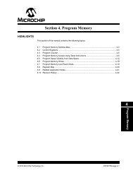
<strong>Section</strong> <strong>45.</strong> <strong>High</strong>-<strong>Speed</strong> <strong>Analog</strong> <strong>Comparator</strong>HIGHLIGHTSThis section of the manual contains the following major topics:<strong>45.</strong>1 Introduction .................................................................................................................. 45-2<strong>45.</strong>2 Features Overview....................................................................................................... 45-2<strong>45.</strong>3 Module Description ...................................................................................................... 45-3<strong>45.</strong>4 Control Registers ......................................................................................................... 45-4<strong>45.</strong>5 Configuring the <strong>High</strong>-<strong>Speed</strong> <strong>Analog</strong> <strong>Comparator</strong>......................................................... 45-7<strong>45.</strong>6 Application Information ................................................................................................ 45-8<strong>45.</strong>7 <strong>High</strong>-<strong>Speed</strong> <strong>Analog</strong> <strong>Comparator</strong> Limitations................................................................ 45-9<strong>45.</strong>8 Register Maps............................................................................................................ 45-10<strong>45.</strong>9 Related Application Notes.......................................................................................... 45-11<strong>45.</strong>10 Revision History ......................................................................................................... 45-1245<strong>High</strong>-<strong>Speed</strong> <strong>Analog</strong><strong>Comparator</strong>© 2007 Microchip Technology Inc. DS70296A-page 45-1
<strong>dsPIC33F</strong> Family Reference Manual<strong>45.</strong>1 INTRODUCTIONThe <strong>High</strong>-<strong>Speed</strong> <strong>Analog</strong> <strong>Comparator</strong> module in the <strong>dsPIC33F</strong> Switch Mode Power Supply(SMPS) and Digital Power Conversion device family provides a way to monitor voltage andcurrents in a power conversion application.The <strong>High</strong>-<strong>Speed</strong> <strong>Analog</strong> <strong>Comparator</strong> module contains up to four high-speed analog comparatorswith dedicated 10-bit Digital-to-<strong>Analog</strong> Converters (DACs) that provide a programmablereference voltage to one input of the comparator.<strong>45.</strong>2 FEATURES OVERVIEWThe following is a list of key features of the <strong>High</strong>-<strong>Speed</strong> <strong>Analog</strong> <strong>Comparator</strong> module:• Up to four analog comparators• Dedicated 10-bit DAC for each analog comparator• Programmable output polarity• Interrupt generation capability• Up to 16 selectable input sources• DAC output• Multiple voltage references for the DAC:- AVDD/2- Internal Reference 1.2V ±1%- External Reference < (AVDD – 1.6V)• <strong>Analog</strong>-to-Digital Converter (ADC) sample and convert trigger capability• Ability to disable the <strong>High</strong>-<strong>Speed</strong> <strong>Analog</strong> <strong>Comparator</strong> module to reduce power consumption• Functional support for <strong>High</strong>-<strong>Speed</strong> Power Supply PWM module, which includes:- PWM Duty Cycle Control- PWM Period Control- PWM Fault DetectDS70296A-page 45-2© 2007 Microchip Technology Inc.
<strong>Section</strong> <strong>45.</strong> <strong>High</strong>-<strong>Speed</strong> <strong>Analog</strong> <strong>Comparator</strong><strong>45.</strong>3 MODULE DESCRIPTIONFigure 45-1 shows a functional block diagram of one analog comparator from the <strong>High</strong>-<strong>Speed</strong><strong>Analog</strong> <strong>Comparator</strong> module.The analog comparator provides high speed operation with a typical delay of 20 ns. Thecomparator has a typical offset voltage of ±5 mV. The negative input of the comparator is alwaysconnected to the DAC circuit. The positive input of the comparator is connected to an analogmultiplexer that selects the desired source pin.The analog comparator input pins are typically shared with pins used by the ADC module. Boththe comparator and the ADC can use the same pins at the same time. This capability enables auser to measure an input voltage with the ADC and detect voltage transients with the comparator.Figure 45-1:SMPS <strong>Comparator</strong> Module Block DiagramCMPxA*INSELCMPxB*CMPxC*MUXTrigger to PWMStatusCMPxD*CMPx*01Glitch FilterPulseGeneratorRANGECMPPOLAVDD/2INTREFMUXDACDACOUTInterrupt RequestAVSS10CMREFDACOEEXTREF*x = 1, 2, 3, and 445<strong>High</strong>-<strong>Speed</strong> <strong>Analog</strong><strong>Comparator</strong>© 2007 Microchip Technology Inc. DS70296A-page 45-3
<strong>dsPIC33F</strong> Family Reference Manual<strong>45.</strong>4 CONTROL REGISTERSThe following registers are used to configure the <strong>High</strong>-<strong>Speed</strong> <strong>Analog</strong> <strong>Comparator</strong> module:• <strong>Comparator</strong> Control Register x (CMPCONx)This register is used to configure the comparator voltage reference source, input pin andoutput polarity. Depending on the device variant, there are up to four individual registers(CMPCON1-CMPCON4), which correspond to the respective comparator.• <strong>Comparator</strong> DAC Control Register x (CMPDACx)The contents of this register determine the threshold voltage for the comparator.Depending on the device variant, there are up to four individual registers(CMPDAC1-CMPDAC4), which correspond to the respective comparator.DS70296A-page 45-4© 2007 Microchip Technology Inc.
<strong>Section</strong> <strong>45.</strong> <strong>High</strong>-<strong>Speed</strong> <strong>Analog</strong> <strong>Comparator</strong>Register 45-1:<strong>Comparator</strong> Control Register x (CMPCONx)R/W-0 U-0 R/W-0 U-0 U-0 U-0 U-0 R/W-0CMPON — CMPSIDL — — — — DACOEbit 15 bit 8R/W-0 R/W-0 R/W-0 U-0 R-0 U-0 R/W-0 R/W-0INSEL EXTREF — CMPSTAT — CMPPOL RANGEbit 7 bit 0Legend:R = Readable bit W = Writable bit U = Unimplemented bit, read as ‘0’-n = Value at POR ‘1’ = Bit is set ‘0’ = Bit is cleared x = Bit is unknownbit 15 CMPON: <strong>Comparator</strong> A/D Operating Mode bit1 = <strong>Comparator</strong> module is enabled0 = <strong>Comparator</strong> module is disabled (reduces power consumption)bit 14 Unimplemented: Read as ‘0’bit 13 CMPSIDL: <strong>Comparator</strong> Stop in Idle Mode bit1 = Discontinue module operation when device enters Idle mode0 = Continue module operation in Idle modeIf a device has multiple comparators, any CMPSIDL bit set to ‘1’ will disable all comparators while inIdle mode.bit 12-9 Reserved: Read as ‘0’bit 8bit 7-6DACOE: DAC Output Enable1 = DAC analog voltage is output to DACOUT pin (1)0 = DAC analog voltage is not connected to DACOUT pinINSEL: <strong>Comparator</strong> Input Source Select bit00 = Select CMPxA input pin01 = Select CMPxB input pin10 = Select CMPxC input pin11 = Select CMPxD input pinbit 5EXTREF: External Reference Enable bit1 = External source provides reference to DAC (maximum DAC voltage determined by externalvoltage source)0 = Internal reference sources provide reference to DAC (maximum DAC voltage determined byRANGE bit setting)bit 4 Reserved: Read as ‘0’bit 3CMPSTAT: Current state of comparator output including CMPPOL selectionbit 2 Reserved: Read as ‘0’bit 1bit 0CMPPOL: <strong>Comparator</strong> Output Polarity Control bit1 = Output is inverted0 = Output is not invertedRANGE: DAC Output Voltage Range bit1 = <strong>High</strong> range: Max DAC value = AVDD/2 (1.65V @ 3.3V AVDD)0 = Low range: Max DAC value = INTREF (1.2V ±1%)45Note 1:DACOUT can only be associated with a single comparator at any given time.<strong>High</strong>-<strong>Speed</strong> <strong>Analog</strong><strong>Comparator</strong>© 2007 Microchip Technology Inc. DS70296A-page 45-5
<strong>dsPIC33F</strong> Family Reference ManualRegister 45-2:<strong>Comparator</strong> DAC Control Register x (CMPDACx)U-0 U-0 U-0 U-0 U-0 U-0 R/W-0 R/W-0— — — — — — CMREFbit 15bit 8R/W-0 R/W-0 R/W-0 R/W-0 R/W-0 R/W-0 R/W-0 R/W-0CMREFbit 7 bit 0Legend:R = Readable bit W = Writable bit U = Unimplemented bit, read as ‘0’-n = Value at POR ‘1’ = Bit is set ‘0’ = Bit is cleared x = Bit is unknownbit 15-10 Reserved: Read as ‘0’9-0 CMREF: <strong>Comparator</strong> Reference Voltage Select bits1111111111 = (CMREF • INTREF/1024) or (CMREF • (AVDD/2)/1024) volts depending on RANGEbit, or (CMREF • EXTREF/1024) if EXTREF bit is set•••0000000000 = 0.0 voltsDS70296A-page 45-6© 2007 Microchip Technology Inc.
<strong>Section</strong> <strong>45.</strong> <strong>High</strong>-<strong>Speed</strong> <strong>Analog</strong> <strong>Comparator</strong><strong>45.</strong>5 CONFIGURING THE HIGH-SPEED ANALOG COMPARATORThe <strong>High</strong>-<strong>Speed</strong> <strong>Analog</strong> <strong>Comparator</strong> module is configured using the CMPCONx register. TheINSEL bits are used to select the comparator input pin. The signal to be monitored must beconnected to this pin.The EXTREF bit in the CMPCONx register selects between an external reference source or theinternal reference source. If the EXTREF bit is set (CMPCONx = 1), the voltage applied tothe EXTREF pin provides the comparator reference voltage.If the EXTREF bit is cleared (CMPCONx = 0), the RANGE bit (CMPCONx) in theCMPCONx register determines the comparator reference voltage. If Low Range is selected(CMPCONx = 0), the internal band gap reference (INTREF) provides the comparatorreference. If <strong>High</strong> Range is selected (CMPCONx = 1), AVDD/2 provides the comparatorreference.<strong>45.</strong>5.1 10-bit DACEach analog comparator in the <strong>High</strong>-<strong>Speed</strong> <strong>Analog</strong> <strong>Comparator</strong> module has a dedicated 10-bitDAC that is used to program the comparator threshold voltage.Each DAC has an output enable bit (DACOE) in the <strong>Comparator</strong> Control (CMPCONx)register that enables the DAC reference voltage to be an output on the device (DACOUT).DACOUT can only be associated with a single comparator at any given time. When more thanone DACOE bit is set, the DACOUT pin will reflect the DAC output of the comparator with thehighest priority. The comparator priority is based on the comparator number, with <strong>Comparator</strong> 1having the highest priority.The full range of the DAC (AVDD/2) will typically be used when the chosen input source pin isshared with an ADC input.The reduced range option (INTREF) is typically used when monitoring currents via a currentsense shunt resistor. Usually, the measured voltages in such applications are small (< 1.25V);therefore, the option of using a reduced reference range for the comparator extends the availableDAC resolution in these applications.The use of an external reference enables the user to connect to a reference that better suits theirapplication.<strong>45.</strong>5.2 Interaction with Digital I/O Pin BuffersIf the <strong>High</strong>-<strong>Speed</strong> <strong>Analog</strong> <strong>Comparator</strong> module is enabled and a pin has been selected as thesource for the comparator, then the digital input buffer associated with that pin will be disabled.This is done to prevent excessive currents in the digital buffer due to analog input voltages.<strong>45.</strong>5.3 Glitch FilterThe <strong>High</strong>-<strong>Speed</strong> <strong>Analog</strong> <strong>Comparator</strong> module provides a glitch filter for the comparator output tomask transient signals less than two instruction cycles in a duration. In Sleep or Idle mode, theglitch filter is bypassed to enable an asynchronous signal from the comparator to the interruptcontroller. This asynchronous signal can be used to wake up the processor from Sleep or Idlemode.<strong>45.</strong>5.4 Operation in Sleep and Idle ModesThe comparator can be disabled while in Idle mode if the CMPSIDL bit in the CMPCONx registeris set (CMPCONx = 1). Setting the CMPSIDL bit for any one of the comparators causes theentire <strong>High</strong>-<strong>Speed</strong> <strong>Analog</strong> <strong>Comparator</strong> module to be disabled while in Idle mode.If the <strong>High</strong>-<strong>Speed</strong> <strong>Analog</strong> <strong>Comparator</strong> module is disabled (CMPCONx = 0), all of the analogcomparators and the DACs are disabled to reduce power consumption.45<strong>High</strong>-<strong>Speed</strong> <strong>Analog</strong><strong>Comparator</strong>© 2007 Microchip Technology Inc. DS70296A-page 45-7
<strong>dsPIC33F</strong> Family Reference Manual<strong>45.</strong>6 APPLICATION INFORMATIONThe <strong>High</strong>-<strong>Speed</strong> <strong>Analog</strong> <strong>Comparator</strong> module provides high-speed analog comparators that canbe used in many power conversion applications. The outputs of the <strong>High</strong>-<strong>Speed</strong> <strong>Analog</strong><strong>Comparator</strong> module can be used to perform the following functions:• Generate an interrupt• Trigger an ADC sample and convert process• Truncate the PWM signal (current limit)• Truncate the PWM period (current reset)• Disable the PWM outputs (fault-latch)The output of the <strong>High</strong>-<strong>Speed</strong> <strong>Analog</strong> <strong>Comparator</strong> module can be used in multiple modes at thesame time. For example, comparator output can be used to generate an interrupt, have the ADCtake a sample and convert it, and truncate the PWM output, all in response to a voltage beingdetected beyond its expected value.The comparator can also be used to wake up the system from Sleep or Idle mode when theanalog input voltage exceeds the programmed threshold voltage.The potential applications of the <strong>High</strong>-<strong>Speed</strong> <strong>Analog</strong> <strong>Comparator</strong> module are numerous andvaried. The following section describes some typical applications in power conversion circuits.<strong>45.</strong>6.1 Power Factor Correction Boost Converter: PWM Reset Using<strong>High</strong>-<strong>Speed</strong> <strong>Analog</strong> <strong>Comparator</strong><strong>Analog</strong> comparators are widely used in a Power Factor Correction Boost Converter as shown inFigure 45-2. The <strong>High</strong>-<strong>Speed</strong> <strong>Analog</strong> <strong>Comparator</strong> module can be utilized for this applicationinstead of adding expensive circuitry. The <strong>High</strong>-<strong>Speed</strong> <strong>Analog</strong> <strong>Comparator</strong> is used in conjunctionwith the <strong>High</strong>-<strong>Speed</strong> Power Supply PWM module to generate the Current Reset mode PWMsignal. For more information on this PWM mode of operation, refer to <strong>Section</strong> 43: “<strong>High</strong>-<strong>Speed</strong>Power Supply PWM”.The <strong>High</strong>-<strong>Speed</strong> <strong>Analog</strong> <strong>Comparator</strong> is configured to reset the PWM module when the measuredcurrent through the inductor falls below the minimum acceptable current level. This minimumcurrent level is determined by the application.Initially, the power semiconductor switch is turned ON. After a constant ON time, the switch isturned OFF and the PWM module waits for the current to decay below the comparator threshold.When the current falls below the threshold, the comparator resets the PWM module, turning thepower semiconductor switch back ON and thereby energizing the inductor again.Figure 45-2:Application of Current Reset PWM ModeProgrammed PeriodPWM1HTONTOFFILPWM1HActual PeriodSMPS <strong>Comparator</strong> resets PWM counterPWM cycle restarts earlyLDVOUT+IL+CINCOUTACINPWM1HDS70296A-page 45-8© 2007 Microchip Technology Inc.
<strong>Section</strong> <strong>45.</strong> <strong>High</strong>-<strong>Speed</strong> <strong>Analog</strong> <strong>Comparator</strong><strong>45.</strong>7 HIGH-SPEED ANALOG COMPARATOR LIMITATIONS<strong>45.</strong>7.1 <strong>Comparator</strong> Input RangeThe analog comparator has a limitation for the input Common Mode Range (CMR) of(AVDD – 1.5V) typical. This means that both inputs to the comparator (the chosen CMPx inputpin and the selected reference source) should be within this range. As long as one of the inputsis within the CMR, the comparator output will be correct. However, any input exceeding the CMRlimitation will cause the comparator input to be saturated.If both inputs exceed the CMR, the comparator output will be indeterminate.<strong>45.</strong>7.2 DAC Output RangeThe maximum reference voltage input to the DAC should not exceed (AVDD – 1.6V). If theexternal reference voltage input exceeds this value, the DAC output will become indeterminate.<strong>45.</strong>7.3 EXTREF RangeIf EXTREF is selected as the comparator reference source, the voltage at the EXTREF pinshould not exceed (AVDD – 1.5V). If the voltage at EXTREF exceeds this value, the comparatoroutput can become unpredictable.45<strong>High</strong>-<strong>Speed</strong> <strong>Analog</strong><strong>Comparator</strong>© 2007 Microchip Technology Inc. DS70296A-page 45-9
<strong>dsPIC33F</strong> Family Reference Manual<strong>45.</strong>8 REGISTER MAPSA summary of the registers associated with the <strong>High</strong>-<strong>Speed</strong> <strong>Analog</strong> <strong>Comparator</strong> module is provided in Table 45-1.Table 45-1: <strong>Analog</strong> <strong>Comparator</strong> Control Register MapFile Name ADR Bit 15 Bit 14 Bit 13 Bit 12 Bit 11 Bit 10 Bit 9 Bit 8 Bit 7 Bit 6 Bit 5 Bit 4 Bit 3 Bit 2 Bit 1 Bit 0 AllResetsCMPCON1 0540 CMPON — CMPSIDL — — — — DACOE INSEL EXTREF — CMPSTAT — CMPPOL RANGE 0000CMPDAC1 0542 — — — — — — CMREF 0000CMPCON2 0544 CMPON — CMPSIDL — — — — DACOE INSEL EXTREF — CMPSTAT — CMPPOL RANGE 0000CMPDAC2 0546 — — — — — — CMREF 0000CMPCON3 0548 CMPON — CMPSIDL — — — — DACOE INSEL EXTREF — CMPSTAT — CMPPOL RANGE 0000CMPDAC3 054A — — — — — — CMREF 0000CMPCON4 054C CMPON — CMPSIDL — — — — DACOE INSEL EXTREF — CMPSTAT — CMPPOL RANGE 0000CMPDAC4 054E — — — — — — CMREF 0000DS70296A-page 45-10© 2007 Microchip Technology Inc.
<strong>Section</strong> <strong>45.</strong> <strong>High</strong>-<strong>Speed</strong> <strong>Analog</strong> <strong>Comparator</strong><strong>45.</strong>9 RELATED APPLICATION NOTESThis section lists application notes that are related to this section of the manual. Theseapplication notes may not be written specifically for the <strong>dsPIC33F</strong> product family, but theconcepts are pertinent and could be used with modification and possible limitations. The currentapplication notes related to the <strong>High</strong>-<strong>Speed</strong> <strong>Analog</strong> <strong>Comparator</strong> module are:Title Application Note #No related applications notes at this time.Note:Please visit the Microchip web site (www.microchip.com) for additional ApplicationNotes and code examples for the <strong>dsPIC33F</strong> family of devices.45<strong>High</strong>-<strong>Speed</strong> <strong>Analog</strong><strong>Comparator</strong>© 2007 Microchip Technology Inc. DS70296A-page 45-11
<strong>dsPIC33F</strong> Family Reference Manual<strong>45.</strong>10 REVISION HISTORYRevision A (September 2007)This is the initial release of this document.DS70296A-page 45-12© 2007 Microchip Technology Inc.