Download - Panasonic Biomedical
Download - Panasonic Biomedical
Download - Panasonic Biomedical
- No tags were found...

Create successful ePaper yourself
Turn your PDF publications into a flip-book with our unique Google optimized e-Paper software.
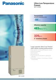
Operating InstructionsBlood Bank RefrigeratorMBR-1405GRMBR-1405GR SeriesPlease read these instructions carefully before using this product, and save this operating instructionsfor future use.See page 35 for all model numbers.
CONTENTSINTRODUCTION P. 3PRECAUTIONS FOR SAFE OPERATION P. 4ENVIRONMENTAL CONDITIONS P. 8REFRIGERATOR COMPONENTSRefrigerator unit P. 9Inside of front cover P. 11Control panel components P. 12INSTALLATION SITE P. 13INSTALLATION P. 14START-UP OF UNIT P. 15PLACING OF STORAGE ITEMS P. 16PREPARATION OF MONITOR BOTTLE P. 17DISPLAY OF CHAMBER TEMPERATURE P. 18DEFROSTING OF EVAPORATOR P. 18REMOTE ALARM TERMINAL P. 19CALIBRATION OF SENSOR P. 20ALARM FUNCTIONS P. 21SELF DIAGNOSTIC FUNCTIONS P. 22ROUTINE MAINTENANCECleaning of exterior, interior, and accessories P. 23Checking of alarm operation P. 23Cleaning of condenser filter P. 24Cleaning of evaporating tray P. 24Replacement of fluorescent lamp P. 25Replacement of glow starter P. 26REPLACEMENT OF BATTERY P. 27TROUBLESHOOTING P. 28DISPOSAL OF UNIT P. 29Recycle of battery P. 29Decontamination of unit P. 29SPECIFICATIONS P. 34PERFORMANCE P. 35SAFETY CHECK SHEET P. 362
INTRODUCTIONRead this operating instructions carefully before using the appliance and follow the instructions forsafety operation.Our company never guarantee any safety if the appliance is used for any objects other than intendeduse or used by any procedures other than those mentioned in this operating instructions.Keep this operating instructions in an adequate place to refer to it as necessary.The contents of the operating instructions will be subjected to change without notice due to theimprovement of performance or functions.Contact our sales representative or agent if any page of the operating instructions is lost or page orderis incorrect.Contact our sales representative or agent if any point in this operating instructions is unclear or if thereare any inaccuracies.No part of this operating instructions may be reproduced in any form without the expressed writtenpermission of our company.CAUTIONOur company guarantees the product under certain warranty conditions. Our company in noway shall be responsible for any loss of content or damage of content.3
PRECAUTIONS FOR SAFE OPERATIONIt is imperative that the user complies with this operating instructionsas it contains important safety advice.Items and procedures are described so that you can use this unit correctly and safely.If the precautions advised are followed, this will prevent possible injury to the user andany other person.Precautions are illustrated in the following way:WARNINGFailure to observe WARNING signs could result in a hazard to personnelpossibly resulting in serious injury or death.CAUTIONFailure to observe CAUTION signs could result in injury to personnel anddamage to the unit and associated property.Symbol shows;this symbol means caution.this symbol means an action is prohibited.this symbol means an instruction must be followed.Be sure to keep this operating instructions in a place accessible to users of this unit.< Label on the unit >This mark is labeled on the cover in which the electrical components of high voltageare enclosed to prevent the electric shock.The cover should be removed by a qualified engineer or a service personnel only.4
PRECAUTIONS FOR SAFE OPERATIONWARNINGDo not use the unit outdoors. Current leakage or electric shock may result if the unit is exposed torain water.Only qualified engineers or service personnel should install the unit. The installation byunqualified personnel may cause electric shock or fire.Install the unit on a sturdy floor and take an adequate precaution to prevent the unit fromturning over. If the floor is not strong enough or the installation site is not adequate, this may resultin injury from the unit falling or tipping over.Never install the unit in a humid place or a place where it is likely to be splashed by water.Deterioration of the insulation may result which could cause current leakage or electric shock.Never install the unit in a flammable or volatile location. This may cause explosion or fire.Never install the unit where acid or corrosive gases are present as current leakage or electricshock may result due to corrosion.Always ground (earth) the unit to prevent electric shock. If the power supply outlet is notgrounded, it will be necessary to install a ground by qualified engineers.Never ground the unit through a gas pipe, water main, telephone line or lightning rod. Suchgrounding may cause electric shock in the case of an incomplete circuit.Connect the unit to a power source as indicated on the rating label attached to the unit. Useof any other voltage or frequency other than that on the rating label may cause fire or electric shock.Never store volatile or flammable substances in this unit if the container cannot be sealed. Thesemay cause explosion or fire.Do not insert metal objects such as a pin or a wire into any vent, gap or any outlet on the unit.This may cause electric shock or injury by accidental contact with moving parts.Use this unit in safe area when treating the poison, harmful or radiate articles. Improper usemay cause bad effect on your health or environment.Turn off the power switch (if provided) and disconnect the power supply to the unit prior to anyrepair or maintenance of the unit in order to prevent electric shock or injury.Do not touch any electrical parts (such as power supply plug) or operate switches with a wethand. This may cause electric shock.5
PRECAUTIONS FOR SAFE OPERATIONWARNINGEnsure you do not inhale or consume medication or aerosols from around the unit at the time ofmaintenance. These may be harmful to your health.Never splash water directly onto the unit as this may cause electric shock or short circuit.Never put containers with liquid on the unit as this may cause electric shock or short circuit whenthe liquid is spilled.Never bind, process, or step on the power supply cord, or never damage or break the powersupply plug. A broken supply cord or plug may cause fire or electric shock.Do not use the supply cord if its plug is loose. Such supply cord may cause fire or electric shock.Never disassemble, repair, or modify the unit yourself. Any such work carried out by anunauthorized person may result in fire, or electric shock or injury due to a malfunction.Disconnect the power supply plug if there is something wrong with the unit. Continuedabnormal operation may cause electric shock or fire.When removing the plug from the power supply outlet, grip the power supply plug, not the cord.Pulling the cord may result in electric shock or fire by short circuit.Disconnect the power supply plug before moving the unit. Take care not to damage the powercord. A damaged cord may cause electric shock or fire.Disconnect the power plug when the unit is not used for long periods. Keeping the connectionmay cause electric shock, current leakage, or fire due to the deterioration of insulation.If the unit is to be stored unused in an unsupervised area for an extended period, ensure thatchildren do not have access and that doors cannot be closed completely.The disposal of the unit should be accomplished by appropriate personnel. Remove doors toprevent accidents such as suffocation.Do not put the packing plastic bag within reach of children as suffocation may result.6
PRECAUTIONS FOR SAFE OPERATIONCAUTIONUse a dedicated power source (a dedicated circuit with a breaker) as indicated on the rating labelattached to the unit. A branched circuit may cause fire resulting from abnormal heating.Connect the power supply plug to the power source firmly after removing the dust on the plug.A dusty plug or improper insertion may cause a heat or ignition.Never store corrosive substances such as acid or alkali in this unit if the container cannot besealed. These may cause corrosion of inner components or electric parts.Check the setting when starting up of operation after power failure or turning off of powerswitch. The stored items may be damaged due to the change of setting.Be careful not to tip over the unit during movement to prevent damage or injury.Prepare a safety check sheet when you request any repair or maintenance for the safety of servicepersonnel.7
ENVIRONMENTAL CONDITIONSThis equipment is designed to be safe at least under the following conditions (based on the IEC 61010-1):Indoor use;Altitude up to 2000 m;Temperature 5 o C to 40 o CMaximum relative humidity 80% for temperature up to 31 o C decreasing linearly to 50% relative humidityat 40 o C;Mains supply voltage fluctuations up to ±10% of the nominal voltage;Transient overvoltages up to the levels of OVERVOLTAGE CATEGORY Ⅱ;Temporary OVERVOLTAGES occurring on the mains supply;Applicable pollution degree of the intended environment (POLLUTION DEGREE 2 in most cases);8
REFRIGERATOR COMPONENTSRefrigerator unit12 Light switch 3Front cover [page 11]Door gasketTemperature recorder10459Florescent lamp[page 25]Outer doorMBR-1405GR876119
REFRIGERATOR COMPONENTS1. Door alarm switch: This switch detects the door status (open/close). The door check lamp is ONwhen the door is open and the alarm buzzer sounds with 2 minutes delay. [page 21]2. Control panel: With the key on the control panel, temperature display can be changed and the alarmtest is available. Also, the running status can be checked on the temperature display and an indicator.[page 12]3. Air intake vent (upper front): Do not block this vent. Blocking this vent may cause unstablechamber temperature. Do not insert fingers or similar articles into the vent.4. Monitor bottle (upper and lower): A sensor to display the chamber temperature is attached to themonitor bottle. Fill the bottle with 200 mL of 10% glycerol fluid or water before commencing theoperation. [page 17]5. Access port (right and left side): This port allows a sensor or cable of measuring equipment to enterthe chamber from outside.Replace the insulation and the rubber caps when the access port is not used. Improper replacementmay cause rise of chamber temperature or condensation around the access port.6. Leveling foot (front, 2 locations): These are screw bolts used to install and fix the unit. Adjust theheight of the leveling feet by turning the screw bolts until 2 front casters are away from the floor. [page 14]7. Dew receiver: The condensation on the outer door is accumulated on this dew receiver. Wipe off thewater on the dew receiver with a cloth.The condensation may be found on the outer door frame with ambient humidity of about 50%R.H. andon the glass surface of the outer door with ambient humidity of about 60%R.H. This is not a malfunction.8. Drawer (MBR-1405GR): The maximum load is 40 kg per drawer.Shelf (MBR-1405G): The set location is adjustable. The maximum load is 40 kg per shelf.Items to be stored in the chamber must be placed on the shelves or drawers. Do not put storageitems directly on the bottom of the chamber.9. Inner door: This prevents the cold air from escaping when the outer door is opened. Always closethe inner door surely before closing the outer door.10. Air exhaust vent (bottom): Do not block this vent. Blocking this vent may cause unstable chambertemperature. Arrange the storage items not to subject to the cold air from this vent.11. Evaporating tray: Defrost water from the evaporator accumulates on the evaporating tray andevaporates into the atmosphere. See page 24 for cleaning.10
REFRIGERATOR COMPONENTSInside of front cover1 2 3541. Condenser filter: This filter is to prevent dust from plugging the condenser. Clean the condenserfilter once a month. See page 24 for cleaning.2. Remote alarm terminal: Refer to page 19.3. Power switch: “|”; ON, “○”; OFF.4. Glow starter: This is for the fluorescent lamp. Replace the glow starter when the fluorescent lampis replaced. For the replacement, refer to page 26.5. Battery switch (at the bottom): ON-OFF switch for built-in battery for power failure alarm. Alwaysturn on this switch when the blood bank refrigerator is operated to assure the power failure alarm. Turnoff this switch when the blood bank refrigerator is not used for long period to protect the battery.11
REFRIGERATOR COMPONENTSControl panel components1 23 4511 10 9 8 7 61. Door check indicator (DOOR): The red LED lamp is lit when the outer door is opened.2 minutes after the door check indicator is ON, the buzzer is activated to notice the door opening.[page 21]2. Alarm indicator (ALARM): The red LED lamp blinks during an alarm status. [page 21]3. Temperature display indicator (LOWER): This lamp is lit when the lower monitor bottle temperatureis displayed or when the average temperature of lower and upper monitor bottle temperature is displayedon the temperature display.4. Temperature display indicator (UPPER): This lamp is lit when the upper monitor bottle temperatureis displayed or when the average temperature of lower and upper monitor bottle temperature is displayedon the temperature display.5. Temperature display: Normally this shows the present chamber temperature and during an alarmstatus, this shows a blinking chamber temperature [page 21]. And an error code and a blinking chambertemperature is displayed alternately when the self diagnostic function detects any abnormality. [page 22]6. Up arrow key ( ): This key is used at calibration mode of sensor for temperature display. Pressingthis key at calibration mode causes the numerical value to change. [page 20]7. Scroll key ( ): This key is for service and used by a service personnel only.8. Calibration key (CAL): This key is used for the calibration of sensor for temperature display.Pressing this key for more than 5 seconds leads “calibration mode”. [page 20]Use this key only when the calibration of sensor for temperature display is necessary.9. Temperature display changeover key (UPPER/LOWER): By pressing this key, the displayedtemperature is changed in sequence; upper temperature, lower temperature, and average temperature ofupper and lower temperature. [page 18]10. Alarm test key (ALARM TEST): This key is used to check the operation of alarm buzzer, alarmindicator and remote alarm terminal. [page 21]11. Alarm buzzer stop key (BUZZER): Pressing this key silences the alarm buzzer when the alarmindicator blinks and the alarm buzzer sounds.12
INSTALLATION SITETo operate this unit properly and to obtain maximum performance, install the unit in a location with thefollowing conditions:A location not compliance with the following conditions may cause poor performance, failure oraccident.A location not subjected to direct sunlightDo not install the unit under direct sunlight. Installation in a location subjected to direct sunlight maydegrade the performance.A location with adequate ventilationLeave at least 10 cm around the unit for ventilation. Poor ventilation will result in a reduction of theperformance and consequently the failure.A location away from heat generating sourcesAvoid installing the unit near heat-emitting appliances such as a heater or a boiler etc. Heat candecrease the intended performance of the unit.A location with little temperature changeInstall the unit under stable ambient temperature. Installing the unit under unstable ambient temperaturemay result in unstable performance.A location with a sturdy and level floorAlways install the unit on a sturdy and level floor withstanding the total weight of the unit. The unevenfloor or tilted installation may cause failure or injury. Unstable condition may cause vibration or noise.A location not prone to high humidityInstall the unit in the ambient of 80% R.H. or less humidity. Installation under high humidity may causecurrent leakage or electric shock.CAUTIONThe unit may collect excessive frost on the evaporator if it is installed in high temperature and highhumidity location. This will cause frequent defrosting.A location without flammable or corrosive gasNever install the unit in a flammable or volatile location. This may cause explosion or fire or may resultin the current leakage or electric shock by the corrosion of the electrical components.CAUTIONNever install the unit in a location where the corrosive material such as sulfur compound is likelyto be generated (near a drainage facilities, etc). Corrosion of the copper pipe may result indeterioration of cooling unit and consequently the failure.A location without the possibility of anything fallAvoid installing the unit in the location where anything can fall down onto the unit. This may cause thebreakdown or failure of the unit.13
INSTALLATION1. After unpackagingRemove all transportation packaging materials and tapes. Open the doors and ventilate the unit. If theoutside panels are dirty, clean them with a diluted neutral dishwashing detergent.Undiluted detergent can damage the plastic components. For the dilution, refer to the instruction ofthe detergent.After the cleaning with the diluted detergent, always wipe it off with a wet cloth. Then wipe off thepanels with a dry cloth.Note:Remove the cable tie banding the power supply cord. Prolonged banding may cause the corrosion ofthe cord coating.2. Installing the unitExtend the leveling feet by rotating them counterclockwiseto separate 2 front casters from the floor. [Fig. 1]And adjust the leveling feet to level the unit.The unit is installed firmly by separating the front castersfrom the floor. The unit may be moved at the time ofopening/closing the door if the front casters contact withfloor.3. Fixing the unit2 fixtures are attached on the rear of the unit. These keepadequate space between the unit and wall and also can beused for fixing the unit. Fix the unit to the wall by usingthese fixtures and a rope or chain. [Fig. 2]Leveling footFixtureFig. 14. Ground (earth) the unitThe ground (earth) is for preventing the electric shock inthe case of the electrical insulation is somehow degraded.Always ground the unit at the time of installation.A 3-prong plug with grounding pole is provided to theposer supply cord. There is no need for electric work forgrounding.If the power supply outlet is not grounded, it will benecessary to install a ground by qualified engineers.Fig. 214
START-UP OF UNITFollow the procedures for the initial and consequent operations of the unit.At the recovery from power failure, the operation is start-up automatically with temperature setting of 4±1.5 o C1. With the blood bank refrigerator empty, connect the power supply plug to the dedicated outlet withappropriate rating, and turn on the power switch.The alarm buzzer operates. Silence the alarm buzzer by pressing the alarm buzzer stop key(BUZZER). The alarm buzzer recovers after 30 minutes. (This is caused by high temperature alarmfunction and not a malfunction.)2. Fill the monitor bottles with 10% glycerol fluid or water of 200 mL. [page 17]Close the doors (outer and inner door) securely. The door check indicator is lit when the outer door isopen. The alarm buzzer activates when the outer door is opened for more than 2 minutes. The alarmbuzzer is canceled when the outer door is closed.3. The chamber temperature is set to 4±1.5 o C at the factory. Check that the chamber temperaturereaches 4±1.5 o C on the temperature display.Check that the chamber temperature falls to 4±1.5 o C on the temperature display when the start-upafter cleaning, maintenance or moving.4. Turn on the light switch to check the fluorescent lamp is on. After checking, turn off the light switch ifthe light is not necessary.5. Turn on the battery switch.Always turn on the battery switch when the blood bank refrigerator is operating to assure the powerfailure alarm.6. Begin slowly placing items into the chamber to minimize the temperature rise.Never put the storage items on the bottom of the chamber. Always put the storage items on the shelf orin the drawer.The outer door has a condensation on the glass during refrigerator operation. Wipe off the condensationwith a dry soft cloth. Also, wipe off the water on the dew receiver regularly.15
PLACING OF STORAGE ITEMSDo not disturb the air circulation in the chamber by the storage items. The disturbed air circulation cancause the freezing of storage items or degrade of temperature distribution in the chamber.Air intake ventDo not block the air intake by the storage items near the air intake vent. Care should be taken not to putany paper or plastic chips near the air intake vent. They may be vacuumed up and block the air intakevent.Air exhaust ventDo not block the air exhaust by the storage items near the air exhaust vent. Care should be taken not toput storage items nearby the air exhaust vent. The storage items may be frozen.Load line [Fig. 3]The storage area is limited to ensure the air flow in the chamber. The labels “load line” are attached tothe right and left side of the chamber. Always put the storage items within the area limited by the labels.CAUTIONNever block the air intake or exhaust vent. Also, never disturb the air circulation therefore, place thestorage items with adequate space.Never store corrosive substances such as acid or alkali in this unit if the container cannot be sealed.These may cause corrosion of inner components or electric parts.Air intakeventLoad lineAir exhaustventAir circulationRange of thecontainersLoad lineContainers< Section view >Fig. 316
PREPARATION OF MONITOR BOTTLEBefore start-up of the operation, fill the monitor bottles (upper and lower) with 10% glycerol fluid or waterof 200 mL by following the procedure below.1. Remove the bottom shelf (for model MBR-1405G) orremove the top and bottom drawer (for modelMBR-1405GR).2. Remove the cover on the monitor bottle.The cover is fixed by the upper and lower clicks. It canbe removed by pulling the upper side forward as shown infigure 1.Recorder sensor(upper monitor bottle)Sensor fortemp. display3. Take out the sensor for temperature display from themonitor bottle.The sensor for temperature display is not fixed,therefore it is removed together with the cover.For the upper monitor bottle, take out the recordersensor as well.Fixing screwCoverFig. 14. Remove the fixing screws (2 screws) and take out themonitor bottle.Cap5. Remove the cap (screw type) on the monitor as shownin the figure 2.Loosen6. Pour 10% glycerol fluid or water of 200 mL into themonitor bottle.7. Cap the monitor bottle and fix the monitor bottle to itsoriginal location by the fixing screws.Fig. 28. Set the sensor for temperature display to the monitor bottle and replace the cover.For the upper monitor bottle, set the recorder sensor as well.9. Replace the bottom shelf (for model MBR-1405G) or replace the top and bottom drawer (for modelMBR-1405GR).17
DISPLAY OF CHAMBER TEMPERATUREThe chamber temperature is set to 4±1.5 o C at the factory. The temperature on the temperature displayshows the temperature of sensor for temperature display attached to the monitor bottle (upper and lower).By pressing the temperature display changeover key, the displayed temperature is changed in sequence;upper temperature, lower temperature, and average temperature of upper and lower temperature. Thetable 1 shows the procedure for changeover.The upper temperature is the representative of high temperature and the lower temperature is therepresentative of low temperature. Accordingly, the displayed temperature is not always 4±1.5 o C.This is not a malfunction.Table 1. Changeover of temperature display●: Lamp ON ○: Lamp OFFOperation Key operated Indication after operation Display mode1Plug-in the power supplyplug and turn on thepower switch.-----Average temperatureis displayed.● UPPER● LOWERAveragetemperature2Press the temperaturedisplay changeover key.UPPERLOWERUpper temperature isdisplayed.● UPPER○ LOWERUppertemperature3Press the temperaturedisplay changeover key.UPPERLOWERLower temperature isdisplayed.○ UPPER● LOWERLowertemperature4Press the temperaturedisplay changeover key.UPPERLOWERAverage temperatureis displayed.● UPPER● LOWERAveragetemperature5 Repeat from step 2.DFROSTING OF EVAPORATORThe following 2 defrost methods are adopted in this unit. Both of them are controlled automatically.Cycle defrostTo keep the chamber temperature stable, the compressor is cycled on and off. During “off” period anyfrost which has accumulated on the evaporator is melted by energizing a defrost heater. This will nothave any discernible effect on the chamber temperature.Forced defrostWhen the ambient humidity is high, or a large amount of damp product is being stored in the chamber,there is a possibility that cycle defrost may not be enough to remove all of the frost on the evaporator. Inthis case, a forced defrost can be initiated.When the unit is operating under a forced defrost, the current chamber temperature and “dF” is displayedalternately on the temperature display.Once the forced defrost is completed, the normal operation resumes. The temperature of blood bag(400 mL) in the chamber rises by approximately 1 to 2 o C during the forced defrost.18
REMOTE ALARM TERMINALThe alarm status is noticed to a remote location when a remote alarm equipment (commercial item) isconnected to the remote alarm terminal. It is recommended to install a remote alarm equipment(commercial item) when the blood bank refrigerator is installed in a desolate location so that an alarmstatus is noticed to an operator.Contact our representative or agent for the installation of a remote alarm equipment (commercial item).Location of remote alarm terminal: inside the front coverAllowable contact capacity: DC 30 V・2 AContact output:between COM and N.O. between COM and N.C.At normal status open closeAt abnormal status close openThe alarm status of remote alarm terminal is cancelled by pressing the alarm buzzer stop key(BUZZER) since the remote alarm terminal is operated in conjunction with alarm buzzer. However, thealarm status of remote alarm terminal is not cancelled by pressing the alarm buzzer stop key (BUZZER)when the unit is under power failure alarm.The remote alarm terminal is in alarm status when the power supply plug is unplugged because it isregarded as a power failure. In this case, the alarm status of remote alarm terminal is not cancelled bypressing the alarm buzzer stop key (BUZZER).Connection of remote alarm terminal1. Open the front cover by pulling firmly on both lowercorners of the front cover.N.C. COM N.O.2. Connect the lead wire of a remote alarm equipment(commercial item) to the terminal. [Fig.1]3. Replace the front cover.Fig. 119
CALIBRATION OF SENSORThe temperature on the temperature display shows the temperature of sensor for temperature displayattached to the monitor bottle (upper and lower).Follow the procedure below when the calibration of the sensor for temperature display is necessary.1. Remove the cover on the monitor bottle as shown infigure 1.2. Take out the sensor for temperature display from thechamber.For the upper monitor bottle, it has a recorder sensor(left side) as well. Care should be taken not to take outthe recorder sensor.3. Prepare a bottle or beaker with a solution of crushed iceand cold water. Agitate the mixture thoroughly.4. Put the sensor for temperature display to be calibratedin the mixture.5. Select the temperature display by pressing temperaturedisplay changeover key to show the temperature of sensorfor temperature display to be calibratedFor the changeover of temperature display, refer topage 17.Recorder sensor(upper bottle)Sensor fortemp. displayCover Fig. 16. While sometimes agitating the mixture, allow the temperature indicated on the temperature display tobe stable.7. Calibration is needed if the temperature on the temperature display does not show 0 o C.8. Press the calibration key (CAL) on the control panel for 5 seconds.The temperature display shows C00.9. Set an identification code for sensor for temperature display by using the up arrow key ( ).The identification code for upper sensor for temperature display: C01The identification code for lower sensor for temperature display: C02.Never set any identification code other than C01, C02.10. Press the calibration key (CAL).11. Check that the temperature shown on the temperature display is approximately 0 o C.Repeat the above procedure through 6 to 10 if the temperature shown on the temperature display isout of range of 0±0.2 o C.12. Take out the sensor for temperature display from the mixture and wipe it with a dry and soft cloth.13. Replace the sensor for temperature display and fix it with a cover.For the upper monitor bottle, also replace and fix the recorder sensor.20
ALARM FUNCTIONSThis unit has the alarm functions shown below.Contact our sales representative or agent if the alarm status continues because there is a possibility ofany failure.Alarms Situation Indication Alarm buzzer Remote alarmHigh temp.alarmLow temp.alarmPower failurealarmDoor alarmIf the temperature of the upperor lower sensor for temp.display is higher than 6 o C.If the temperature of the upperor lower sensor for temp.display is lower than 2 o C.At the power failure.If the power supply plug isunplugged.When power switch of off.When the outer door is open.Alarm indicator blinks.Displayed temp. blinks.Alarm indicator blinks.Displayed temp. blinks.Alarm indicator blinks.Temperature display isoff.Door check indicatorlights.Intermittent toneIntermittent toneIntermittent toneIntermittent tone with2 minutes delay.Alarm statusAlarm statusAlarm status.The alarm status of remote alarm terminal is cancelled by pressing the alarm buzzer stop key(BUZZER) since the remote alarm terminal is operated in conjunction with alarm buzzer. However, thealarm status of remote alarm terminal is not cancelled by pressing the alarm buzzer stop key (BUZZER)when the unit is under power failure alarm.This unit is provided with the alarm buzzer recovery function. The alarm buzzer will operate againafter 30 minutes if the alarm status continues even if the alarm buzzer was silenced by pressing the alarmbuzzer stop key (BUZZER).The power failure alarm is kept for approximately 24 hours (when the battery is charged fully). 2-dayoperation of blood bank refrigerator is necessary to charge the fully discharged battery to full level. Aremote alarm keeps alarm status even if the battery is discharged.The blood bank refrigerator resumes the operation with 4±1.5 o C setting at the recovery from thepower failure.-----Checking of alarm operationThe alarm operation can be checked by the procedure below.1. Press the alarm test key (ALARM TEST).2. The alarm indicator blinks, the alarm buzzer sounds intermittently, and the remote alarm is in alarmstatus. This is kept for 90 seconds and finished automatically.During the 90 seconds, the alarm buzzer can not be silenced by pressing the alarm buzzer stop key(BUZZER).3. The alarm operation can be canceled by pressing the alarm test key (ALARM TEST) again during the90 seconds.21
SELF DIAGNOSTIC FUNCTIONSThis unit has the self diagnostic functions shown below.Contact our sales representative or agent if an error code (ex. E03) is displayed resulting from the selfdiagnostic.Self diagnostic Situation Indication Alarm buzzer Remote alarmAlarm indicator blinks.If the defrost sensor isE03 and chamber temp. isdisconnected.displayed alternately.SensorabnormalityBattery checkFan motor checkIf the defrost sensor isshort-circuited.If the compressor sensor isdisconnected.If the compressor sensor isshort-circuited.If the low temp. alarm sensor isdisconnected.If the low temp. alarm sensor isshort-circuited.If the upper sensor for temp.display is disconnected.If the upper sensor for temp.display is short-circuited.If the lower sensor for temp.display is disconnected.If the lower sensor for temp.display is short-circuited.When about 3 years have passedwith the power switch on.(time to replace the battery)When about 6 years have passedwith the power switch on.(time to replace the fan motor)Alarm indicator blinks.E04 and chamber temp. isdisplayed alternately.Alarm indicator blinks.E05 and chamber temp. isdisplayed alternately.Alarm indicator blinks.E06 and chamber temp. isdisplayed alternately.Alarm indicator blinks.E13 and chamber temp. isdisplayed alternately.Alarm indicator blinks.E14 and chamber temp. isdisplayed alternately.Alarm indicator blinks.E15 and chamber temp. isdisplayed alternately.Alarm indicator blinks.E16 and chamber temp. isdisplayed alternately.Alarm indicator blinks.E17 and chamber temp. isdisplayed alternately.Alarm indicator blinks.E18 and chamber temp. isdisplayed alternately.F-1 and chamber temp. isdisplayed alternately.F-2 and chamber temp. isdisplayed alternately.Intermittent tone----- ---------- -----Alarm statusThe alarm status of remote alarm terminal is cancelled by pressing the alarm buzzer stop key(BUZZER) since the remote alarm terminal is operated in conjunction with alarm buzzer. However, thealarm status of remote alarm terminal is not cancelled by pressing the alarm buzzer stop key (BUZZER)when the unit is under power failure alarm.This unit is provided with the alarm buzzer recovery function. The alarm buzzer will operate againafter 30 minutes if the alarm status continues even if the alarm buzzer was silenced by pressing the alarmbuzzer stop key (BUZZER).22
ROUTINE MAINTENANCEWARNINGAlways disconnect the power supply to the unit prior to any repair or maintenance of the unit inorder to prevent electric shock or injury.Ensure you do not inhale or consume medication or aerosols from around the unit at the time ofmaintenance. These may be harmful to your health.Cleaning of exterior, interior, and accessoriesUse a dry cloth to wipe off small amounts of dirt on the outside and inside of the unit and all accessories.If the outside panels are dirty, clean them with a diluted neutral dishwashing detergent.Wipe off the condensation on the glass or exterior of the cabinet with a dry soft cloth.Undiluted detergent can damage the plastic components. For the dilution, refer to the instruction ofthe detergent.After the cleaning with the diluted detergent, always wipe it off with a wet cloth. Then wipe off thecabinet or accessories with a dry cloth. Never pour water onto or into the unit. This may cause electric shock or failure.CAUTIONDo not use a brush, an acid, a thinner, a laundry soap, a powder detergent, boiling water forcleaning. These cause damage of painted surface or failure of plastic and rubber components. Also, donot wipe the plastic and rubber components by a volatile material.Checking of alarm operationCheck the alarm operation regularly (once per 6 months) to assure the alarm is activated at the time ofpower failure. The alarm operation can be checked by the procedure below.1. Press the alarm test key (ALARM TEST).2. The alarm indicator blinks, the alarm buzzer sounds intermittently, and the remote alarm is in alarmstatus. This is kept for 90 seconds and finished automatically.During the 90 seconds, the alarm buzzer can not be silenced by pressing the alarm buzzer stop key(BUZZER).3. The alarm operation can be canceled by pressing the alarm test key (ALARM TEST) again during the90 seconds.23
ROUTINE MAINTENANCECleaning of condenser filterThe condenser filter is installed inside the front cover. Clean the condenser filter every 6 months to keepthe appropriate cooling performance.1. Open the front cover by pulling firmly on both lowercorners of the front cover. [Fig. 1]Condenser filter2. Raise the shaft, and insert end of a shaft in black hole ofthe front cover. This keeps the front cover from fallingback.3. Tug gently on black tab on lower center of condenserfilter to remove the condenser filter.4. Clean the condenser filter with a vacuum cleaner orwater.Fig. 15. Thoroughly dry the condenser filter when using water to clean it.6. After cleaning the condenser filter, return it to the original position and replace the front cover.Cleaning of evaporating trayThe evaporating tray is installed on the back of the unit. Clean the evaporating tray once a month.1. Remove the tray fixture under the evaporating tray byunscrewing 4 screws and the evaporating tray is free. [Fig.1]2. Wash away any accumulated dirt in the evaporatingtray.3. Fix the evaporating tray with the tray fixture and 4screws.EvaporatingtrayTray fixtureFig.124
ROUTINE MAINTENANCEReplacement of fluorescent lampFollow the procedure below when replacing a fluorescent lamp. The fluorescent lamp is locatedvertically at the back of the center mullion. [Fig. 1]1. Turn off the light switch and power switch and thendisconnect the power supply plug.Center mullion2. Move the stored items on the left shelves (drawers) tothe right shelves (drawers). Then remove all shelves(drawers) on the left side.Water-proofcover3. Pull the fluorescent lamp backwards with the lamp coverto remove the fluorescent lamp from the clips (2 locations)together with the lamp cover and the wiring.4. After removing the water-proof cover, remove the socketwith the wiring on the both sides of the lamp cover.Clip5. Take out the fluorescent lamp from the lamp cover andinsert a new fluorescent lamp in it.6. Replace the socket with the wiring and the water-proofcover on the both sides of the lamp cover.Fluorescent lampFig. 17. Fix the lamp cover with the clip (2 locations).8. Replace the shelves (drawers) on the left side and return the stored items.9. Connect the power supply plug to the outlet and turn on the power switch.10. Turn on the light switch to check the fluorescent lamp is on.25
ROUTINE MAINTENANCEReplacement of glow starterThe glow starter is located inside the front cover. [Fig. 1]1. Turn off the light switch and power switch and then disconnect the power supply plug.2. Lift the front cover by pulling firmly on both lower corners of the front cover. Then raise the shaft, andinsert end of a shaft in black hole of the front cover. This keeps the front cover from falling back.3. Remove the glow starter and install a new glow starter. (glow starter; FG-1P)4. Replace the front cover.5. Connect the power supply plug to the outlet and turn on the power switch.6. Turn on the light switch to check the fluorescent lamp is on.Glow starterFig. 126
REPLACEMENT OF BATTERYReplace the battery for power failure alarm every 3 years (when F-1 and chamber temperature isdisplayed alternately to ensure the alarm is operated in the event of power failure. Contact our salesrepresentative or agent for the replacement of battery when F-1 and chamber temperature is displayedalternately.The alarm function (blink of alarm indicator, sound of alarm buzzer) will not operate when the batteryfor power failure alarm is flat.The alarm indicator blinks and the alarm buzzer sounds by the battery for power failure alarm. Theregular replacement of the battery for power failure alarm is important to prevent the rise of chambertemperature in the case of unexpected situation.WARNINGThe replacement of the battery for power failure alarm should be executed by a qualified engineer or aservice personnel only. The replacement of the battery for power failure alarm involves the risk ofelectric shock.The used battery is a recyclable precious resource. Do not dispose of the battery. Always follow theprocedure for recycling.Replacement of battery for power failure alarmThe battery for power failure alarm is located at the backof the control panel. [Fig. 1] The battery is accessiblefrom the top of the blood bank refrigerator.Battery1. Turn off the light switch and power switch and thendisconnect the power supply plug.2. Remove the cover behind the control panel byunscrewing 4 screws.3. Disconnect the connector, loosen 2 screws fixing theFig. 1battery bands and then remove the battery. [Fig. 2]ConnectorBatteryBattery bandAlways put an insulating tape on the terminal portion of theused battery to prevent the short circuit.4. Fix a new battery with 2 screws and battery bands, andthen connect the connector.5. Replace and fix the cover with 4 screws.6. Connect the power supply plug to the outlet and turn onthe power switch.Fig. 227
TROUBLESHOOTINGIf the unit malfunctions, check out the following before calling for service.If the malfunction is not eliminated after checking the following items or the malfunction is not shown inthe table below, contact our sales representative or agent.MalfunctionIf nothing operates evenwhen plugged inThe alarm is activated atstart-upThe alarm is activatedduring operationNoisyWhen chamber does notget cold enoughThe displayed temperatureis not 4 o CCheck/RemedyThe unit is not connected to the power supply properly.The capacity and voltage of power supply is not sufficient.There is a power failure.The circuit breaker on the supply circuit is activated.A breaker of 15 A or more is recommended.The fuse on the supply circuit is blown.The alarm status is kept until the chamber temperature reaches theset temperature.The alarm buzzer recovers after 30 minutes even if the alarm buzzeris silenced by pressing the alarm buzzer stop key (BUZZER).The unit is not connected to the power supply properly.The capacity and voltage of power supply is not sufficient.There is a power failure.The circuit breaker on the supply circuit is activated.A breaker of 15 A or more is recommended.The fuse on the supply circuit is blown.The outer door was kept opened for a long time.The outer door is opened.An error code is displayed on the temperature display. [page 22]Contact our sales representative or agent.The floor is not sturdy.The installation site is not level.The blood bank refrigerator is tilted.The cabinet contacts the surrounding wall.The outer door is frequently opened.The inner door is open.The unit is in direct sunlight.The ventilation around the unit is blocked.There is a nearby heat source.The ambient temperature is too high.The allowable ambient temperature is between 5 and 35 o C.The storage items are too much.The air exhaust vent is blocked up with storage items.The access port is not covered.The access port should be covered with the insulation and rubbercaps when no use.The door gasket is damaged.If it is damaged, contact our sales representative or agent forreplacement.Any foreign substance is located between door gaskets.The displayed temperature between 3 and 5 o C (depending on theambient temperature) is not a malfunction28
DISPOSAL OF UNITWARNINGIf the unit is to be stored unused in an unsupervised area for an extended period ensure that childrendo not have access and doors cannot be closed completely.The disposal of the unit should be accomplished by appropriate personnel. Always removedoors to prevent accidents such as suffocation.Recycle of batteryThe unit contains a rechargeable battery. The battery is recyclable. At the endof it’s useful life, check with you local solid officials option or proper disposal.廢 電 池請 回 收*Label indication is obliged to comply with Taiwanese battery regulation.Decontamination of unitBefore disposal of unit, decontaminate the unit yourself.29
DISPOSAL OF UNIT(English)FOR EU USERSThe symbol mark and recycling systems described below apply to EU countries and do not apply tocountries in other areas of the world.Your <strong>Panasonic</strong> product is designed and manufactured with high quality materials and components whichcan be recycled and/or reused.The symbol mark means that electrical and electronic equipment, batteries and accumulators, at theirend-of-life, should be disposed of separately from your household waste.Note:If a chemical symbol is printed beneath the symbol mark, this chemical symbol means that the battery oraccumulator contains a heavy metal at a certain concentration. This will be indicated as follows: Hg:mercury, Cd: cadmium, Pb: leadIn the European Union there are separate collection systems for used electrical and electronic equipment,batteries and accumulators.Please, dispose of them correctly at your local community waste collection/recycling centre.Please, help us to conserve the environment we live in!(German)Für EU-StaatenDas Symbol und das erwähnte Wiederverwertungssystem gelten nur für die Länder der EU und nicht fürandere Länder oder Gebiete in der Welt.Die Produkte von <strong>Panasonic</strong> werden aus hochwertigen Materialien und Komponenten gefertigt, die sichwieder verwenden lassen.Das Symbol bedeutet, dass elektrische oder elektronische Geräte, Batterien und Akkus am Ende ihrerLebensdauer nicht im Haushaltmüll entsorgt werden dürfen.Hinweis:Ein chemisches Zeichen unter dem Symbol bedeutet, dass die Batterie bzw. der Akku Schwermetalle ingewissen Konzentrationen enthält. Die Metalle werden wie folgt bezeichnet: Hg: Quecksilber, Cd:Kadmium, Pb: BleiIn der Europäischen Union gibt es separate Sammelstellen für elektrische und elektronische Geräte,Batterien und Akkus.Entsorgen Sie solche Geräte bitte richtig in der kommunalen Sammelstelle bzw. im Recyclingzentrum.Helfen Sie mit, die Umwelt in der wir leben, zu schützen.30
DISPOSAL OF UNIT(French)POUR LES UTILISATEURS DE UELe symbole et les systèmes de recyclage évoqués ci-dessous s'appliquent uniquement aux pays de UE.Votre produit <strong>Panasonic</strong> est conçu et fabriqué avec des composants et des matériaux de hautes qualitésqui peuvent être recyclés et/ou réutilisés.Le symbole signifie que les équipements électriques et électroniques, les batteries et les accumulateursne doivent pas être mis au rebut avec les déchets domestiques à l'issue de leur durée de vie.Remarque:Si un symbole chimique est imprimé sous le symbole, le symbole chimique indique que la batterie oul'accumulateur contient une certaine concentration de métaux lourds. Les métaux sont indiqués de lamanière suivante: Hg: mercure, Cd: cadmium, Pb: plomb.Il existe différents systèmes de collecte pour les équipements électriques et électroniques, les batteries etles accumulateurs usagés au sein de l'Union européenne.Veuillez mettre les équipements au rebut de manière correcte, auprès de votre centre de recyclage/decollecte des déchets local.Aidez-nous à préserver l'environnement dans lequel nous vivons!Les machines ou appareils électriques et électroniques contiennent fréquemment des matières qui, sielles sont traitées ou éliminées de manière inappropriée, peuvent s’avérer potentiellement dangereusespour la santé humaine et pour l’environnement.Cependant, ces matières sont nécessaires au bon fonctionnement de votre appareil ou de votre machine.Pour cette raison, il vous est demandé de ne pas vous débarrasser de votre appareil ou machine usagéavec vos ordures ménagères.(Spanish)PARA USUARIOS DE LA UNION EUROPEAEl símbolo y los sistemas de reciclado descriptos a continuación se aplican para países de la UniónEuropea y no se aplica para países en otras áreas del mundo.Su producto <strong>Panasonic</strong> fue diseñado y fabricado con materiales de alta calidad y componentes quepueden ser reciclados y/o vueltos a usar.El símbolo significa que los equipos eléctricos y electrónicos, baterías y acumuladores, al final de su vidaútil, debe ser desechados separadamente de sus residuos domiciliarios.Nota:Si hay un símbolo químico impreso debajo del símbolo, este símbolo químico significa que la batería oacumulador contiene una cierta concentración de un metal pesado. Esto es indicado de la siguientemanera: Hg: mercurio, Cd: cadmio, Pb: plomoEn la Unión Europea hay sistemas de recolección separados para equipos eléctricos y electrónicos,baterías y acumuladores usados.Por favor, disponga de ellos correctamente en el centro de recolección de residuos/reciclado de lacomunidad de su localidad.Por favor, ayúdenos a proteger el medio ambiente en que vivimos!31
DISPOSAL OF UNIT(Portuguese)PARA UTILIZADORES DA UEO símbolo e os sistemas de reciclagem descritos abaixo aplicam-se aos países da UE e não se aplicamaos países noutras áreas do mundo.O seu produto <strong>Panasonic</strong> foi concebido e fabricado com materiais e componentes de elevada qualidadeque podem ser reciclados e/ou reutilizados.O símbolo significa que o equipamento eléctrico e electrónico, baterias e acumuladores, em final de vida,não devem ser deitados fora juntamente com o lixo doméstico.Atenção:Se estiver impresso um símbolo químico debaixo do símbolo de , este símbolo químico significa que abateria ou acumulador contém um metal pesado numa determinada concentração. Estará indicado daseguinte forma: Hg: mercúrio, Cd: cádmio, Pb: chumboNa União Europeia existem sistemas de recolha separados para equipamento eléctrico e electrónico,baterias e acumuladores.Por favor, entregue-os no seu centro de reciclagem/recolha de lixo local.Por favor, ajude-nos a conservar o ambiente!(Italian)PER UTENTI UEIl simbolo e i sistemi di riciclaggio descritti di seguito si applicano esclusivamente ai paesi dell’UE.Questo prodotto <strong>Panasonic</strong> è stato progettato e realizzato con materiali e componenti di elevata qualitàche possono essere riciclati e/o riutilizzati.Il simbolo di riciclaggio mostrato di seguito indica che i dispositivi elettrici ed elettronici, le batterie e gliaccumulatori, una volta esauriti, devono essere smaltiti separatamente rispetto ai rifiuti domestici.Nota:Se sotto il simbolo di riciclaggio appare un simbolo chimico, esso sta ad indicare che la batteria ol’accumulatore contengono metalli pesanti a determinate concentrazioni. Questo viene specificato comesegue: Hg: mercurio, Cd: cadmio, Pb: piombo.Nell’Unione europea esistono diversi sistemi per la raccolta dei rifiuti speciali quali i dispositivi elettrici edelettronici, le batterie e gli accumulatori.Si raccomanda di provvedere allo smaltimento di tali rifiuti secondo quanto previsto dalle normativevigenti in materia.Aiutaci a conservare l’ambiente!32
DISPOSAL OF UNIT(Dutch)VOOR GEBRUIKERS IN DE EUHet symbool en de recycleersystemen die hieronder beschreven worden, zijn van toepassing op delanden in de EU en zijn niet van toepassing op landen in andere delen van de wereld.Uw <strong>Panasonic</strong> product is ontworpen en gemaakt met materialen en onderdelen van hoge kwaliteit, diegerecycleerd en opnieuw gebruikt kunnen worden.Het symbool betekent dat elektrische en elektronische apparatuur, batterijen en accu's aan het eind vanhun leven apart van uw huisafval weggegooid moeten worden.Let op:Indien een chemisch symbool afgedrukt staat onder het symbool, betekent dit chemisch symbool dat debatterij of accu een zwaar metaal met een bepaalde concentratie bevat. Dit wordt als volgt aangegeven:Hg: kwik, Cd: cadmium, Pb: loodIn de Europese Unie zijn afzonderlijke inzamelingssystemen voor gebruikte elektrische en elektronischeapparatuur, batterijen en accu's.Wilt u deze op de juiste manier weggooien bij uw plaatselijk afvalinzameling-/recyclingcentrum in uwbuurt?Help ons het milieu waarin wij leven in stand te houden!(Swedish)FÖR ANVÄNDARE INOM EUDen symbolmärkning och de återvinningssystem som beskrivs här nedan gäller länder inom EU ochgäller inte länder i någon annan del av världen.Din <strong>Panasonic</strong> -produkt har konstruerats och tillverkats med delar och material av hög kvalitet, som kanåtervinnas och/eller återanvändas.Symbolmärkningen innebär att elektrisk och elektronisk utrustning, batterier och ackumulatorer, vid slutetav deras livslängd, inte får slängas som hushållsavfall utan skall slängas separat.Observera:Om en kemisk symbol finns tryckt under denna symbolmärkning, betyder denna kemiska symbol attbatteriet eller ackumulatorn innehåller en tungmetall med en viss koncentration. Detta indikeras påföljande sätt: Hg: kvicksilver, Cd: kadmium, Pb: blyI den Europeiska Unionen finns det separata uppsamlingssystem för använd elektrisk och elektroniskutrustning, batterier och ackumulatorer.Gör dig av med sådana saker på rätt sätt på den speciella lokala platsen för återsamling/återanvändning.Hjälp oss att bevara den miljö vi lever i!33
SPECIFICATIONSProduct nameBlood Bank RefrigeratorMBR-1405GRExternal dimensionsW1440 mm x D830 mm x H1950 mmInternal dimensionsW1320 mm x D710 mm x H1500 mmEffective capacity1301 LExteriorPainted steelInteriorPainted steelOuter doorPainted steel, Provided with 2-layer glass windowInner doorAcrylic resinInsulationRigid polyurethane foamed-in placeDrawer Stainless steel x 12Allowable load; 40 kg/drawerAccess portInner diameter; 30 mm, Right side, Left sideCooling methodForced cool air circulationCompressor Hermetic type, Output; 250 W x 1EvaporatorFin and tube typeCondenserFin and tube typeRefrigerantR-404ADefrostingCycle defrost + forced defrost, Fully automaticDefrost heater88 WTemperature controllerElectronic control systemThermometerDigital thermometerFluorescent lampWhite light (FL40SD for MBR-1405GR-PA, FL40SSECW for MBR-1405GR-PE)Glow starter; FG-4PAlarmsHigh temp. alarm, Low temp. alarm, Power failure alarm, Door alarmBatteryFor power failure alarm (DC 6 V1100 mAh, automatic recharge)Remote alarm contactAllowable contact capacity: DC 30 V・2 AWeight315 kgTemperature recorder7 days typeAccessories1 set of keyOptional componentsInterface board (MTR-480, MTR-L03)Design or specifications will be subject to change without notice.Refer to the updated catalog when ordering an optional component.34
PERFORMANCEProduct nameBlood Bank RefrigeratorMBR-1405GRModel number MBR-1405GR-PA MBR-1405GR-PEStorage temperature 4 o C (distribution; ±1.5 o C)Usable ambient temperature5 o C to 35 o CNoise level48 dB (A scale) (50 Hz)Maximum pressure1992 kPaRated voltage AC 115 V AC 230 V/240 VRated frequency 60 Hz 50 HzPower consumption 375 W 360 W/380 WThe above data is measured based on our internal basis.Design or specifications will be subject to change without notice.The unit with CE mark complies with EC directives.35
CAUTIONPlease fill in this form before servicing.Hand over this form to the service engineer to keep for his and your safety.Safety check sheet1. Refrigerator contents :Risk of infection:Risk of toxicity:Risk from radioactive sources:□Yes□Yes□Yes□Yes□No□No□No□No(List all potentially hazardous materials that have been stored in this unit.)Notes :2. Contamination of the unitUnit interiorNo contaminationDecontaminatedContaminatedOthers:□Yes□Yes□Yes□Yes□No□No□No□No3. Instructions for safe repair/maintenance of the unita) The unit is safe to work onb) There is some danger (see below)□Yes□Yes□No□NoProcedure to be adhered to in order to reduce safety risk indicated in b) below.Date :Signature :Address, Division :Telephone :Product name :Model :Serial number : Date of Installation :Blood Bank Refrigerator MBR-Please decontaminate the unit yourself before calling the service engineer.36
1-1-1 Sakata, Oizumi-Machi, Ora-Gun, Gunma 370-0596, Japan© <strong>Panasonic</strong> Healthcare Co., Ltd. 2012Printed in Japan7FB6P151560002S0412-20712