Felix Tellez - SFERA
Felix Tellez - SFERA
Felix Tellez - SFERA
- No tags were found...

Create successful ePaper yourself
Turn your PDF publications into a flip-book with our unique Google optimized e-Paper software.
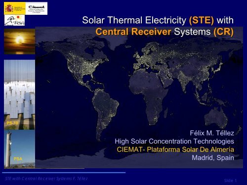
Solar Thermal Electricity (STE) withCentral Receiver Systems (CR)PS-10PSAFélix M. TéllezHigh Solar Concentration TechnologiesCIEMAT- Plataforma Solar De AlmeríaMadrid, SpainSTE with Central Receiver Systems F. TéllezSlide 1
Contents:‣ Overview of STE withCentral ReceiverTechnology‣ Development andState of the Art ofcomponents‣ State of the art ofSTE-CR plants byheat transfer fluids:• Water/Steam• Molten Salts• AirSTE with Central Receiver Systems F. TéllezSlide 2
Main Components of STE with CRReceiverHeliostat Receiver FieldTowerHeliostatsReceiverHeliostat fieldTowerHeat StorageHeat StoragePower BlockSTE with Central Receiver Systems F. TéllezSlide 3
(some) Key factors of STE-CR‣ High Solar Concentration may provide higher overall plant efficiencies (solarfluxes about 100 times larger than in Parabolic Trough technology)‣ The Solar Field (consisting of heliostats, each curved, and provided with trackingmotors) represents around 30-50% of the necessary investment in equipment.‣ The Receiver (combined with its location on the tower) is a key element thatrequires careful technology solutions to ensure high efficiency, easy operationand high durability.‣ The dispatch ability of these systems can be higher than other CSP or STEtechnologies, (Thermal storage of up to 15 hours has been demonstrated and upto 20 hours are under development)‣ Two axes tracking implies:• Higher land requirements (e.g. than Parabolic troughs) ~20% ground occupation(=mirror area/total area)• Lower requirements on civil works for flattening terrains (up to 3-4% is allowed)• Better use of DNI resource (=higher efficiencies) (about a 10% more DNI collectionthan PT for a same aperture)• High investment costs (driving mechanisms)• (probably) Higher cost in maintenance (optical and mechanical) (due to have a“distributed” concentrator)• …STE with Central Receiver Systems F. TéllezSlide 4
CR Systems: A little historySTE with Central Receiver Systems F. TéllezSlide 5
1950’s: ‘Brainstorming’ and firts conceptsSTE with Central Receiver Systems F. TéllezSlide 6
1970’s: Odeillo solar furnace•• Built Built at at the the begining begining of of the the 70s.: 70s.:•63 •63 Flat Flat heliostats heliostats•Thermal •Thermal power power 1 MW. MW.STE with Central Receiver Systems F. TéllezSlide 7
The 1974 oil crisis prompted the development of a variety ofCSP facilities for testing and evaluation of components anddemonstration of plant schemesCentral Solar1- Receptor.2- Campo Heliostatos.3- Torre.4- Almacenamiento.5- Generador Vapor.6- Turbo Alternador.7- Condensador.8- Línea Eléctrica.CESA 1, PSA, Almería, SpainCRS, PSA, Almería, SpainSOLAR 1 &2, Barstow, California, USAACTF Georgia, USANSTTF,Albuquerque, N.M., USA WEIZMMAN, Rehovot, Israel THEMIS, Targassone, France EURELIOS, Adriano, Italy SUNSHINE, Nio, JapónSTE with Central Receiver Systems F. TéllezSlide 8
STE-CR. Actual Characteristics• Two axes tracking is required. HTFTemperatures between 250ºC- 1100 ºC.Solar Fluxes of 300-1000 kW/m2• First Commercial Power Plant (in theworld) inaugurated in March 2007, inSeville (Solucar-PS10),• Numerous demonstration systems havedemonstrated the potential of powertowers.• Cycles Rankine, Brayton and Combined• Actual Peak overall efficiencies (solar toelectricity)~ 17-20%• Mean Annual efficiencies (solar toelectricity): 13-16%• Capacity factors up to ~70% (in Spainand upto 85 % with highest DNI)• Ongoing projects of plants:− ~100 MW in Spain (50 MWe inoperation: PS10, PS20, Gemasolar)− …2,500 MWe in USA. (eSolar,Brightsource, Rocketdine, SolarReserve,…) (5 MWe en operación)− ~200 MWe in Sudáfrica− 50 MWe in MENA− China, India, …?Hot SaltStorage TankConventionalEPGSSteam GeneratorCold SaltStorage TankSTE with Central Receiver Systems F. TéllezCOST AND PERFORMANCE FORECASTS, SL-5641 2003. Slide 9
STE-CR. Actual Characteristics• Learning Curve reactivated with PS10, PS20,eSolar, Gemasolar, …(reduction of ~15% hasbeen achieved in several components –asheliostats- in the firts 4 years of deployment)• Although the maturity is considered lower thanin PT, the greater potential in efficiency andcost reduction of CR plants tends to balancethe deployment of CR and PT plants.• Three preferred technology options: Water-Steam (saturated, superheated, ...), MoltenSalts and Air (atmospheric or presurized).Crimea (URSS)Eurelios en Adrano (Italia)Sunshine-Nio; JapónPSASandia (EE.UU)Weitzman (Israel)SteamSept 20062008PS-20*...STE with Central Receiver Systems F. Téllez20 Steam 2008Solar OneSolar TwoSlide 10
CRS: Some key elements.Component’s options and new DevelopmentSTE with Central Receiver Systems F. TéllezSlide 11
The Heliostat is a key elementA heliostat consists of a large focal curved (~spherical) mirror, providedwith two axes (and composed of facets, foundation and structure, drivingmechanism, controls,…) whose mission is to maintain static the sunlightimage on a certain target (typically on the receiver) throughout the dayFACETSMETALLIC STRUCTUREAZIMUTHDRIVING MECHANISMTORQUE TUBEPEDESTALELEVATIONCONTROLBOXSTE with Central Receiver Systems F. TéllezSlide 12
The heliostat is a key element in terms of overall plantinvestmentSTE with Central Receiver Systems F. TéllezSlide 13
Heliostats – DevelopmentsIn the last three decades a variety of prototypes have been developed and tested.All of them with the main goal of improving performances and/or reducing specificcosts (€uros / m2). (R&D explored: increasing size, lightweight structures,alternative reflecting surfaces, different mechanisms, control boxes, wirelesscommunications,...)STE with Central Receiver Systems F. TéllezSlide 14
Heliostats technology.Examples of prototypes: Stressed Membrane ConceptSAIC Stretched Membrane HeliostatSAIC Multi-Facet Stretched Membrane HeliostatASM 150 Stretched Membrane Heliostat at PSASTE with Central Receiver Systems F. TéllezSlide 15
Heliostats technology.Examples of prototypes: Glass Metal ConceptDecade 1980-1990CASA (CESA1 40 m 2 )ASINEL 65m 2SENER (CESA1 40 m 2 )ATS 150STE with Central Receiver Systems F. TéllezSlide 16
Heliostats technology.Some of the latest developments of prototypes in SpainPCHAH25, H40 SIREC (ETSII)Sanlúcar 120 (PS-10 & PS-20)Space-CilLatest development:PCHA: Design PSA. Autonomous heliostat based on pre-existing Martin-Marietta. First Autonomous Heliostat Field in the World.•Sanlúcar 120: Design Solúcar-ABENGOA. Increase size.New local control (PLC)• H 25: Design PSA. Flat Heliostat for solar furnace. Commercial,decentralized drives.• H40: Design PSA. Spherical Heliostat for tower plant. Commercial,decentralized drives.• Space-Cil: PSA optics & kinematics new concepts, design Solúcar.Cilindrical Heliostat for tower plant.STE with Central Receiver Systems F. TéllezSlide 17
Heliostats technology.Some of the latest developments of prototypes in SpainSENER/GEMASOLAR:-Configuration in “T”-35 facets, 3mm thickreinforced withgalvanized steelstamping support,patented by Sener,- Reflecting surface of115.7 m2,-The foundations aremade of reinforcedconcrete,-Main structure ingalvanized steel,-Drive mechanismpatented by Sener.STE with Central Receiver Systems F. Téllez(Lata, J. et al. 2010)Slide 18
The Optical Quality of the Solar Field (as key) starts with theOptical quality of the heliostat : Curvature / canting of facets andheliostatEach facet is able to reflect and concentrate solar radiation, so thatshould be organized geometrically for joint action by all facets of theheliostat single optical system.This is known as canting (or alignment of the heliostat’s facets) andprovides a single focalHeliostat Before CantingSTE with Central Receiver Systems F. TéllezSlide 19
The Optical Quality of the Solar Field (as key) starts with theOptical quality of the heliostat : Curvature / canting of facets andheliostatHeliostat after CantingAfter CantingCanting purpose toobtain a single focus forall facets of heliostatSTE with Central Receiver Systems F. TéllezSlide 20
Heliostats - Components - Drive MechanismsThis item costs about half the cost of the heliostat. This driving uses two gear motorsthat guide the mirror surface by two rotations: elevation and azimuth.Necessary features:•Sufficient strength to withstand the weight, themobile structure and wind loads, and stiffness toavoid vibration of low frequency.•Ability to generate extremely slow movements.•High positioning accuracy and absence ofbacklash.•Possibility of providing a relatively rapid return tothe position of survival.•Resistance to weathering and atmosphericagents.•Ease of maintenance.•Reduced construction and operation costs.STE with Central Receiver Systems F. TéllezSlide 21
Heliostats - Components - Drive MechanismsEx. Options for “T” type of heliostats: Mechanical vs Hydraulic drivemechanism (f.i. heliostat Sanlucar, …)STE with Central Receiver Systems F. TéllezSlide 22
Heliostats - Components – Control SystemResponsible for basic tasks that ensure the proper daily operation of theheliostat, both the point and in emergency situations. Typically we have twolevels of control: a) Central Control – to stablish setpoints and strategies forheliostat operation, b) Distributed or Local Control (to translate setpoints tothe driving mechanism, …)CONTROLESMOTORESTARJETACONTROLDC / DCCONTROLLOCALSTE with Central Receiver Systems F. TéllezTypical Local Control Tasks:• Solar vector calculus,• Control of drive mechanisms,• Calculation and pointing of heliostat mirrorsurface• Managing of communications with thecentral control• Auto-diagnosis of errors and faults,• Self-protection in an emergency.Slide 23
STE with Central Receiver Systems F. TéllezSlide 24
Emerging concepts: More Modularity -> small Heliostat +multitower SystemsSTE with Central Receiver Systems F. TéllezSlide 25
STE with Central Receiver Systems F. TéllezSlide 26
CRS. Actual status of heliostat developmentASM-150GM-100ATS-150SAIC-170SANLUCAR 120STE with Central Receiver Systems F. Téllez• Heliostat: Actual developments have shown an excellentperformance with a trend to reduce cost by oppositeways:• Larger sizes (from 90 to 150 m2) to attain lowerspecific costs in the driving mechanism (totalinvestment per square meter of aperture, installed)• Smaller sizes (1 to 20 m2) to reduce therequirements on the driving mechanisms, increasingthe land occupation and allowing schemes ofganged tracking• Actual reference may be the Abengoa’s and/or theSener’s heliostats (in operation in PS10, PS20 andGEMASOLAR): Sizes ~ 120 m2• Prices ~160-170 €/m2 (installed)• Optical qualities of 2.5 mrad are easily attained and areenough for the first plants.• Durability of about 20 years has been proved in facilitieslike PSA• New Developments are focused in reducing costs indriving mechanism and lighter structures, reducing thecabling requirements by autonomous heliostat, reducingO&M costs, etc.Slide 27
The optical quality is an issue: The combination ofimperfections (mirrors, canting, structure, tracking, …)lead to a loss of efficiency (“degraded sun”). An errorconvolution may be used to quantify the quality.Angulo solar (teta_s), [mrad]Error Solar (68.3% sign.),mradError estructuraError seguimiento solarError Total (68.3% sign.)Error Total (95% sign.)0.009599333 radianes0.0028 radianes0.001979899 radianes0.002828427 radianes0.004445222 radianes0.008712635 radianesSpherical curvature, no wavinessσ =σ+σ+σ2D2S2sp2cVariability ofFocal ImageSpherical curvature, with wavinessSTE with Central Receiver Systems F. TéllezSummer solstice, 7:30 a.m.Summer Solstice, solar noonSummer Solstice, 7:30 p.m.Slide 28
Besides, the loss of efficiency of each heliostat, the solar field maybe designed (choosing heliostat distribution, tower heigh, receiversize, …) to obtain the optimum compromise of efficiency and costs.Ŋ plant= Ŋ solar_field*ŋ receiver*ŋ power_block= p electricity/ p solar_incidentSTE with Central Receiver Systems F. TéllezSlide 29
Cosine Factor• The cosine factor is one ofthe most important factors foroptimizing the Solar Fieldoptical efficiency.• Due to the cosine factor, theeffective reflection area isreduced.• The cosine factor dependson the sun position and theposition of the heliostat in thefield respect to receiver(including tower height).• Typically an annualestimation of the cosinefactor is used for solar fielddesignBesides, the loss of efficiency of each heliostat, the solar field maybe designed (choosing heliostat distribution, tower heigh, receiversize, …) to obtain the optimum compromise of efficiency and costs.STE with Central Receiver Systems F. TéllezSlide 30
Atmospheric attenuationBesides, the loss of efficiency of each heliostat, the solar field maybe designed (choosing heliostat distribution, tower heigh, receiversize, …) to obtain the optimum compromise of efficiency and costs.In the case of having a very large solar field apertures, many design factors suggest very talltower heights and large heliostat field far from the tower. In these cases, ATMOSPHERICATTENUATION may be a significant efficiency limitation for heliostat fields having a singletower.STE with Central Receiver Systems F. TéllezSlide 31
Solar field Maintenance is required to maintain high levelsof performance (e.g. in reflectivity by mirror washing, etc.)- Required demineralized water of about 0.2liters/kWh- Typical frequencies of washing are 2-3weeksSTE with Central Receiver Systems F. TéllezSlide 32
Solar field design is aimed to choose «optimal» coordinates ofheliostats respect to the tower (+heliostat characteristics,thermal power requirements on receiver + …)Ŋ plant= Ŋ solar_field*ŋ receiver*ŋ power_block= p electricity/ p solar_incidentCOSINE FACTOR SHADOWS +BLOCKSAIR TRANMITTANCESPILLAGE FACTORHeliostat’s positions in fieldTOTAL OPTICAL FIELD EFFICIENCYSTE with Central Receiver Systems F. TéllezSlide 33
Solar Field designs & Relationship with receiver(Receiver may be placed on Top)North fieldCircular field+ secondary reflectionThe use of re-concentratorsTower heigh increases modifies the with field the power andfield arrangement: dispositionMultitowersEverything is linked(Receiver may be placed on the botom)STE with Central Receiver Systems F. TéllezTower cost increses more than linearly with heighSlide 34
STE with Central Receiver Systems F. TéllezSlide 35
Solar field – receiver relationship: Concentratedsolar flux distribution on apertureFlat PlateReceiverCavityReceiverCylindrical ExternalReceiverNon-homogeneous flux distributions over the receiver decreases the efficiencyand the life time of receiver (thermal stress)STE with Central Receiver Systems F. TéllezSlide 36
The Receiver is a key componentThe receiver is a key sub-componentin the development of CentralReceiver technology. From severalpoints of view:• Concentrates most of the perceptionof "technological risk" attributable tothe technology• it may represent a significant part ofthe investment cost (ie ~ 17% inGemasolar)• Its efficiency is a proportional factorin overall plant performance (~ totalelectricity)• Its design continues being achallenge for engineering (since thateach design solution is tailor-madeaccounting for a large set ofconstrains)0,42%2%13%17%Distribución de los costes de inversión14%33%Inversión Total en Campo SolarInversión Total Bloque de PotenciaInversión Total en ReceptorInversión Total TorreInversión Total Caldera de GasInversión Total AlmacenamientoCostes Indirectos20%STE with Central Receiver Systems F. TéllezSlide 37
The choice of the receiver type and designmay attend to several constrains anddesign requirements, like:• High absortivity (ideally ~black body)• The working fluid choice• The nominal conditions in temperatureand solar flux• The placement in relationship to thesolar field,• The “optimal” rate amongPerformance/cost/Durability. (Thisimplies an adequate choice of materialsfor corrosion and oxidation resistance,thermal stress resistance, cost,…)• Modularity to reduce investment andMaintenance costs,• Etc.Two typologies of Receiver/absorber:Tubes and VolumetricSTE with Central Receiver Systems F. TéllezSlide 38
The choice of the receiver type and designmay attend to several constrains anddesign requirements, like:• High absortivity (ideally ~black body)• The working fluid choice• The nominal conditions in temperatureand solar flux• The placement in relationship to thesolar field,• The “optimal” rate amongPerformance/cost/Durability. (Thisimplies an adequate choice of materialsfor corrosion and oxidation resistance,thermal stress resistance, cost,…)• Modularity to reduce investment andMaintenance costs,• Etc.Two typologies of Receiver/absorber:Tubes and VolumetricSTE with Central Receiver Systems F. TéllezSlide 39
Riesgos tecnológicosTechnological risks in the Receiver ~ Technical factorsassociated to the high temperature and high solar flux•Controllability•Stability•Thermal stress•Thermal gradients•Durability•ReliabilitySTE with Central Receiver Systems F. TéllezSlide 40
Heat storage (and hibridization) increase the6 hours of storagedispatchabilityFossil Hybridization‣ CRS as other STE technologieshave a unique integrability into4aconventional thermal plants‣ With thermal storage or fossilfuel backup solar thermal plantscan provide firm capacity withoutthe need of separate backuppower plants and withoutstochastic perturbations of thegrid.‣ Solar thermal can supply peakpower in summerly heat periodswhen hydro and wind are scarce12a 8a noon 4p 8p 12aHEATSTORAGEOPTICAL CONCENTRATORRECEIVERFOSSIL BACKUPW12a 4a 8a noon 4p 8p 12aHOTPOINTCOLD POINTSTE with Central Receiver Systems F. TéllezSlide 41
Capacity of Heat Storage options100000CHEMICAL THERMAL MECHANICALBituminous coal 12000Fuel Oil, Gasoline 9000 - 11000Liquid Natural Gas 5800Methanol 4300Liquid Hydrogen 2380Natural Gas 1000Hydrogen (100 bar) 300Batteries 50 - 100Molten Salts 500 - 700MgO 300Bricks / Pebbles Bed 100Steam (100 bar) 120Glauber´s Salt 100Water 35Rotating Wheels 60Pr. Air (100 bar) 100.8 Pumped Storage (300 m)1000010001001010.1Solar TRESPS-10Air Tech.Volumespecific energy content (kWh/m3)STE with Central Receiver Systems F. TéllezSlide 42
Status of the CRS – Heat Storage• Heat storage (up to 15-20 hours) feasible with2-tank molten salt and about 2-3 hours usingpebbles-beds (for air technologies).• Heat storage for saturated or superheated steamis quite expensive and requires R&D.• The cost goal is about ~20 €/kWhTSASTE with Central Receiver Systems F. TéllezSlide 43
Heat storage using nitrate molten salts (indeedfor CRS)STE with Central Receiver Systems F. TéllezSlide 44
Almacenamiento Heat storage térmico for water para steam SRC con firstvapor: primera implementationsimplementaciónSTE with Central Receiver Systems F. TéllezSlide 45
Operating TemperaturaThermodinamic CycleAvailability of HeatstorageSTE with Central Receiver Systems F. TéllezDistinguished by the heat transfer fluid, there are threeCRS options in competence:Direct SteamGeneration< 290º C Saturated290-550 ºC Superheated550-650 ºC SupercríticRankine(or integration aspreheating in CC)¿!Presurized steam vesel~ 30 mintos(Nitrate) MoltenSaltsAtmospheric &Presurized Air565 ºC 750-900ºCRankine(or integration aspreheating in CC)YesTwo tanks(hot/cold) ~15 hRankine / Brayton(or integration in topof CC)YesPebbles Beds(termocline) ~3 hCapacity Factor (full loadequivalent) 2.200 h/year 2200 - 5.700 3.500 h/yearh/yearOverall Annual13-16 % 14-18 % 14-18 %EfficiencyEstimated cost ofelectricityCommercial Situation(actuales / potenciales)0,17-0,23€/kWh-aPS10, PS20 (Saturado),eSolar (Sobrec.)Brightsource E (Supercrit.)0,14-0,17€/kWh-aGemasolar/SolarTresRockedyne/SolarReserveAbu-Dhabi?0,13-0,16 ¿?€/kWh-a(1ª versión PS10)Pending ¡!Slide 46
CRS with Water-SteamSTE with Central Receiver Systems F. TéllezSlide 47
CR with Direct Steam Generation‣ Cheap, abundant heat transfer fluid with no environmental impact‣ Not required Heat exchanger between solar receiver and Power blockSaturated SteamAdvantages:‣ They have shown its feasibility (conventional boilers, Past demonstrationprojects –as CESA 1, …- and commercial CR plants PS10, …)‣ Easy adaptation of conventional technologies‣ Very low thermal losses (due to low temperature + cavity effect)Disadvantages:‣ Low efficiency of the PBSuperheated steamAdvantages:‣ They may produce (for a same receiver/plant size) up to 20-30% more electricitythan the saturated steam (due to the higher PB efficiency)Disadvantages:‣ Controllability in the receiver due to Phase change‣ Technological risk lead to a recommendation of additional R&D‣ More espensive materials (due to higher temperatures)STE with Central Receiver Systems F. TéllezSlide 48
State of the artSTE with Central Receiver Systems F. TéllezSlide 49
State of the artSTE with Central Receiver Systems F. TéllezSlide 50
STE-CR with Steam.Ex. Optional scheemeSTE with Central Receiver Systems F. TéllezSlide 51
PS10 - PS20. Already in Commercial applicationSTE with Central Receiver Systems F. TéllezSlide 52
PS-10.Daily OperationDaily Operation Phases:‣ 1 – Preheating from the night resting time up toachieve the previous conditions for coupling to theturbine‣ 2 – Starting, turbine connection and operatingpressures stabilization.‣ 3 – Operation, from power production stabilizationupto stopping.‣ 4 – Stop, actions carried out after depressurizationup to turbine decoupling.‣ 5 – Hot re-starting, after a transitory stop (shutdown)STE with Central Receiver Systems F. TéllezSlide 53
PS10 performance in a spring daySTE with Central Receiver Systems F. TéllezSlide 54
PS10. Operation in a day requiring support with gasSTE with Central Receiver Systems F. TéllezSlide 55
Availability‣ PS10 has been in operation almost all the 6317 sunny hours since21.06.07 up to 31.12.08.‣ Total plant availability in this period is larger than 96%.‣ Receiver availability in the period is larger than 99%.STE with Central Receiver Systems F. TéllezSlide 56
Annual electricity productionSTE with Central Receiver Systems F. TéllezSlide 57
Alpine Sun Tower: STE-CR (superheated steam,small heliostats, …) 92 MWe by eSolar inCaliforniaSTE with Central Receiver Systems F. TéllezSlide 58
Ivanpah: 440 MWe (by Brightsource ~Luz2)in California (superheated steam)STE with Central Receiver Systems F. TéllezSlide 59
CRS with Molten SaltsSTE with Central Receiver Systems F. TéllezSlide 60
CRS with Molten SaltsAdvantages‣ The molten salts may be used both to cool the receiver (asHTF) and as heat storage, thus, avoiding the use of a Heatexchanger.‣ Due to the high Capacity factors this seems be themost profitable solution for solar-only schemesSTE with Central Receiver Systems F. TéllezDisadvantages:‣ Operating temperatures are limited to the range 250-600 ºC‣ It requires electrical tracing‣ Risk of Salts FreezingSlide 61
Molten salts receivers are being explored for CRand also for Parabolic TroughCentral Receiver(Torresol, SolarReserve, …)STE with62Central Receiver Systems F. TéllezSlide 62
Precedent Molten Salts receiversReceptores de de SalesSalesTemperatura Temperatura Salida Salida Fluido Fluido 566º 566º CFlujo Flujo incidente incidente 400 400 kW kW / / m 2 2Máximo Máximo Teórico Teórico 800 800 kW/m kW/m 2 2Eficiencia Eficiencia 85-90% 85-90% (SIT)(SIT)STE with Central Receiver Systems F. TéllezReceptor MSEE Albuquerque (NuevoMexico)Absorbedor: 3.8 m de ancho y 3.6 m dealtoPotencia: 5 MW térmicosApertura: 2.1 m de ancho por 3.6 m de Slide 63
Precedent Molten Salts receiversReceptor cavidad con 16 m2aperturaTemperatura sales =250/450ºCVapor 410ºC y 40 barSTE with Central Receiver Systems F. TéllezCentral Themis en Targasonne (Francia)Potencia: 2,5 MWe201 helióstatos y 10.740 m2Torre 106 mSlide 64
Precedent Molten Salts receivers• The largest demonstration of a molten salt power tower was the Solar Twoproject - a 10 MW power tower located near Barstow, CA.• The plant began operating in June 1996. The project successfullydemonstrated the potential of nitrate salt technology.• Some of the key results were: the receiver efficiency was measured to be88%, the thermal storage system had a measured round-trip efficiency ofgreater than 97%, the gross Rankine-turbine cycle efficiency was 34%, allof which matched performance projections.• The overall peak-conversion efficiency of the plantwas measured to 13.5%. The plant successfullydemonstrated its ability to dispatch electricityindependent of collection. On one occasion, theplant operated around-the-clock for 154 hoursstraight.• the project identified several areas to simplify thetechnology and to improve its reliability. On April 8,1999, this demonstration project completed its testand evaluations and was shut down.RadiaciónsolarRadiaciónsolarEnergía almacénmedianochemediodíamedianochemediodíamedianochePotenciaSalidaSTE with Central Receiver Systems F. TéllezSlide 65
CR: First Commercial Power Plants.Solar Tres / GEMASOLAR• Solar Tres Project partially financed by the European Commission (with 5 M€; ContractNo. NNE5/2001/369; with a consortium SENER, CIEMAT, ALSTOM-SIEMENS, SAINTGOBAIN y GHERSA.• Sener & Ciemat (with a budget of 6 M€) validated the receiver Technology• TORRESOL promotes the GEMASOLAR Power plant (Next speech)STE with Central Receiver Systems F. TéllezSlide 66
STE-CR with Molten salts and large heat storage constitute(maybe) the most promising option for «solar electricity»GEMASOLAR: StartingSTE with Central Receiver Systems F. TéllezSlide 67
Molten Salts –(Other Tecnology Promoters: SolarReserve/Rocketdyne (USA)STE with Central Receiver Systems F. TéllezSlide 68
CRS with AirSTE with Central Receiver Systems F. TéllezSlide 69
CRS with AirAdvantages:‣ Working fluid always available‣ Good performance under solar transients‣ Low thermal losses (due cavity effect of volumetricabsorber)‣ Very high working temperatures are feasible (1200ºC achieved)‣ …Disadvantages:‣ Air is not a very good heat transfer medium‣ It is difficult to cool adequately (by air mass flowdistribution) to obtain uniform temperature in theabsorber aperture‣ When requiring pressurized air there are pressurelimitations and maximum sizes of quartz window‣ Integration in C.C. feasible but not commercialSTE with Central Receiver Systems F. TéllezSlide 70
Plant schemeReceiverHot Air 680ºCSteamGeneratorThermalStorage~Heliostat FieldBlowerCold Air110ºCBlowerSteam65 bar, 460ºCPower BlockSTE with Central Receiver Systems F. TéllezSlide 71
Experimental Plant Julich (open volumetric)STE with Central Receiver Systems F. TéllezSlide 72
CRS with (pressurized) AirSTE with Central Receiver Systems F. TéllezSlide 73
Project “Solgate”SRC- Pressurized AirAimed for Solar Combined cycleSTE with Central Receiver Systems F. TéllezSlide 74
STE-CR with Pressurized airAir Pressure Technology•Brayton cycle or combined type•Limitations on receiver design and field ofheliostats•Limitations in size of receiver module byquartz windowsecondary concentratorwindowair inletabsorberair outletSTE with Central Receiver Systems F. TéllezSlide 75
SolHyCo(Gas turbine and Cogeneration)‣Solarization of a commercial Gas turbine (100 kWe)‣Tube receiver for presurized air‣Allowing Co-generation, (e.g. Air conditioning andheating)‣High overall efficiency‣Status: prototype (+ development of new receiver)STE with76Central Receiver Systems F. TéllezSlide 76
• Combined system• Possibility to hybridizate with biodieselPresurized Air: SOLUGAS projectSolugas: Solar Up‐scale Gas Turbine Systemsolar airreceiver800°Cfuel350°C1150°C140 heliostats2 MW e4.6 MW e650°CSTE with77Central Receiver Systems F. TéllezSlide 77
THANKS FOR YOUR ATTENTION !Félix M. TéllezHigh Solar Concentration Technologieswww.psa.es; www.ciemat.es (felix.tellez@ciemat.es)STE with Central Receiver Systems F. Téllez<strong>Felix</strong>.tellez@ciemat.esSlide 78