Study of radiation damage in silicon detectors for high ... - F9
Study of radiation damage in silicon detectors for high ... - F9
Study of radiation damage in silicon detectors for high ... - F9
- No tags were found...

Create successful ePaper yourself
Turn your PDF publications into a flip-book with our unique Google optimized e-Paper software.
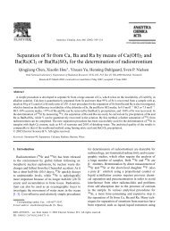
52 3. Ir<strong>radiation</strong> FacilityFigure 3.13: I/V measurement <strong>of</strong> the diode K3. Guard r<strong>in</strong>gs were kept at the same potentialas the pad but their current is not <strong>in</strong>cluded <strong>in</strong> the measurement. Measurement a) was taken 5days after ir<strong>radiation</strong> (stored at 5 C) and was per<strong>for</strong>med at 5 C. The full depletion voltage fromthe C/V measurement at 10 kHz is 30610 V, agree<strong>in</strong>g well with the position <strong>of</strong> the m<strong>in</strong>imum<strong>in</strong> the I/V curve. Value <strong>in</strong> the m<strong>in</strong>imum after the bump (45 A) is taken as the value <strong>of</strong> thebulk generation current at full depletion. b) Measurement <strong>of</strong> the same diode taken after total<strong>of</strong> 5 days at 60 C.From equations 2.38 and 2.9 it follows that the bulk generation current is <strong>in</strong>creas<strong>in</strong>gas the square root <strong>of</strong> the depletion voltage until the sample is fully depleted and thevalues at the plateau could be used to determ<strong>in</strong>e (eq. 2.50). The I/V curve <strong>of</strong> an<strong>in</strong>verted p + -n-n + diode (g. 3.13) however deviates from the expected I / p V shape. Acharacteristic bump can be observed on all samples after <strong>in</strong>version. The explanation hasbeen proposed <strong>in</strong> [51]. After <strong>in</strong>version, the depleted region starts to grow from the n sidewhile guard r<strong>in</strong>gs are on the p side. For low depletion voltages, the surface current isthusnot fully collected by guard r<strong>in</strong>gs, contribut<strong>in</strong>g to the current measured on the centralpad. When the sample is fully depleted guard r<strong>in</strong>gs are fully operational aga<strong>in</strong> (g. 3.13).Thus throughout this work, the leakage current at the m<strong>in</strong>imum after the bump has beenused as the best estimate <strong>of</strong> the bulk generation current.The ma<strong>in</strong> contribution to the error comes from the surface current that rema<strong>in</strong>spresent at the m<strong>in</strong>imum after the bump. As can be seen from data presented later(e.g. g. 4.16), this contribution is rather small <strong>for</strong> diodes with work<strong>in</strong>g guard r<strong>in</strong>gs.The variations <strong>of</strong> the alpha parameter determ<strong>in</strong>ed by this method are at the level <strong>of</strong> few