Installation Instructions - Restoration Hardware
Installation Instructions - Restoration Hardware
Installation Instructions - Restoration Hardware
- No tags were found...

You also want an ePaper? Increase the reach of your titles
YUMPU automatically turns print PDFs into web optimized ePapers that Google loves.
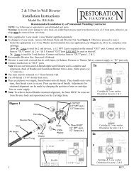
<strong>Installation</strong> <strong>Instructions</strong>Thermostatic Valve and TrimModel No. RH-5744RH-59441
General CharacteristicsIn case of instantaneous heaters, hot water flow has to at least meet flow required by heaterand maintain burning. (Specified by heater manufacturer)Operating SpecificationsHot water supply temperature:Maximum: Reference manufacturing specificationMinimum: 140°FMinimum difference between hot and mixed temperature is: 50°FOperating Pressure:Maximum: 70 PSIMinimum: 20 PSIOperating pressure (on hot and cold line) should be kept as balanced as possible in order toassure maximum efficiency.When the pressure is greater than 70 PSI, a pressure reducer is required. To be fitted beforevalve.Technical DataThe temperature control knob is graduated from 75°F to 120°F with auto stop at 100° toavoid scalding.Temperature limit setting of less than 120°FFit a stop valve/volume control between thermo valve outlet and end devise(s).Plumbing Recommendations• An independent water supply for both hot and cold is required. Do not pipe off ring main.• Large runs of pipe work will cause frictional loss of pressure.• The recommended main water supply piping to valve shall be 3/4” minimum• If more than one valve is installed, the recommended main water supply piping to valveshall be 1” minimum, reducing to 3/4” within 24” of each valve.(Ensure adequate supply from both hot and cold water can be maintained.)Water By-LawsThe mixing valve should be installed in compliance with the water by-laws. For furtherdetails refer to the latest copy of by-laws guide or your local water authority.2
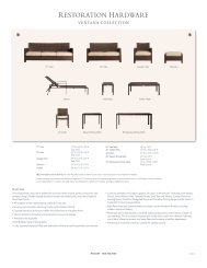
I. Rough in Valve <strong>Installation</strong>Note: Use Teflon tape or equivalent to seal all threaded port joints.1. Do not remove mud cover from valve before locating mounting surface depth in the wall.2. Do not turn the cartridge stem - temperature settings are pre-calibrated at the factory.3. Install plug into one of the two outlet ports. Note: For proper valve operation only one outletport may be used.4. Mount valve to cross support using shims and screws (not included). Valve shall be perpendicularand fixed firmly to cross support to achieve proper trim attachment.5. Place the cross support with valve between wall studs. The min./max. valve exposure templateon the mud cover and vertical height desired within tub/shower enclosure determinesthe exact cross support placement. Attach cross support to wall studs.Cartridge stemDO NOT TURNShimFigure 1PlugWall studCross supportMaximum exposureFinished wallMud covertemplateMinimum exposureFigure 2Mud cover3
II. Connecting Water Supply1. Thoroughly flush supply lines to remove any debris, metallic shavings, flux, etc.2. Shut off water supply to valve.3. Hot and cold water supplies MUST be connected to designated sides for proper operation ofvalve.4. If solder/brazing the fitting connections, pre-assembly hot & cold adapter fittings to copperpiping. Using Teflon tape or equivalent to attach adapter to appropriate inlet port.Important: All excessive heat shall be a minimum of 4” from valve.5. Connect outlet pipe to stop valve/volume control (not included), and from stop valve pipe tovarious end device(s).6. Turn on water supply to valve and check for leaks.Outlet pipefor showerconnection4” min.Hot watersupplyCartridge stem(DO NOT TURN)Figure 3Cold watersupply4
III. Installing Trim & Temperature Setting1. Remove and discard mud cover and screws.2. Slide sleeve over valve body with grooved notch to topside.3. Slide cover plate with gasket over sleeve and attach with decorative screws provided (see Fig.4).4. Orient and position limit stop ring and temperature ring as shown below (see Fig. 5).5. Open shut-off valve and verify water temperature at outlet device by using a thermometer.NOTE: The safe and factory set temperature is 100°F. If the temperature needs to be adjustedfollow step 6, otherwise skip to step 7.6. Rotate cartridge stem to adjust temperature:(clockwise = colder or counterclockwise = hotter)7. Place bonnet onto cartridge stem with red button (100°F) positioned straight up and inlinewith notch on the sleeve (see Fig. 6).8. Secure handle onto bonnet with long flat head screw.9. Press cap onto decorative handle. Remove adhesive backing from button, align and press ontocap.SleeveValveFigure 4Cover PlateStop ringScrewBonnetTemperatureRingCartridgestemCapButtonFigure 5 Figure 6Handle5
Check valve (Reference Fig. 8)1. Turn water supply to valve inlets off.2. Tighten center screw on check valve inward until it clears bottom on check valve slot.3. Unscrew check valve with large bladed screwdriver.4. Remove check valve and clean per previous step 4 and 5.5. Replace valve back into housing, unscrew center and re-close to 7 turns max.6. Turn on water supply to valve inlets.7. Fully open the check valve screws and inspect for leaks.8. Reinstall trim and set temperature per section III.Check valveO-ringFilterFigure 87
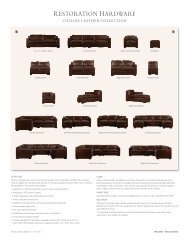
<strong>Restoration</strong> <strong>Hardware</strong>Product Size Specification DiagramMaximum Extension2” ± 1/4”2Max ExtensionShown with RH-5744(Sold separately)
••••••Extension <strong>Installation</strong>Remove trim as shown in Figure 1.Remove STOP RING (1) from VALVE STEM (2).Install extension SLEEVE (3) onto VALVE STEM (2).Reinstall STOP RING (1) onto extension SLEEVE (3).Using the two 8-32 X 3” SCREWS (4) provided with extension kit, reinstall cover PLATE (5).Install nomenclature RING (6) and thermo BONNET (7).Using the M4 X .7 X 70 stainless steel SCREW (8) provided with extension kit, re-attach HAN-DLE (9) and press CAP (10) onto HANDLE (9).6514 3278910Figure 13
Care and CleaningThe lustrous finish on your <strong>Restoration</strong> <strong>Hardware</strong> Bathware fixture shouldbe treated with care. Improper handling or cleaning can damage the surfaceof any metal finish. Use a soft cloth to wipe clean. Avoid harsh abrasivecleaner. Water contains lime and other mineral deposits that will be left onthe surface after the water has evaporated. You can prevent these depositsfrom forming by always wiping the fixture dry immediately after use.Technical Support and Customer ServiceFor technical support in the installation of your <strong>Restoration</strong> <strong>Hardware</strong>Bathware fixture, please call 1-866-417-5207 weekdays between the hoursof 7:00am and 4:00pm PST.For other questions regarding your order, to order additional components ofthe <strong>Restoration</strong> <strong>Hardware</strong> Bathware Collection, to order replacement parts,or to address warranty issues, please contact <strong>Restoration</strong> <strong>Hardware</strong>Customer Service at 1-877-747-4671.4
Thermostatics h o w e r s y s t e m sThermostatic Shower Valve & Trimf e at u r e s & b e n e f i t s• Solid brass components.• Sixteen gallons/minute flow rate supports upto three water outlets running simultaneously.• Temperature control only. <strong>Installation</strong> ofthermostatic valve also requires the purchaseand installation of flow control valve(s) – soldseparately. One flow control valve is neededfor each water outlet in your shower system.(Showerhead, handheld shower, etc).• User accessible, adjustable maximum watertemperature selection.• 3/4" Thermostatic Rough-in Valve, includestrim to match collection.• Paraffin cartridge, Built-in check valves withservice stops, NPT threading Meets ASSEStandard 1016, IAPMO and CSA Listed.Other Components (sold separately):• Flow control valve & trim set.- On/off valve that controls water flow.- One valve needed per water outlet, allowsfor more than one outlet at a time.• Valve trim extension kit. Extends valve anadditional 1-3/8" from wall. Includes spineextension, lock washer and handle screw.Shower Onlyparts required• Thermostatic valve & trim set• Flow control valve & trim set• Showerhead, flange & armShower withHandheld Showerparts required• Thermostatic valve & trim set• Flow control valve & trim set (2)• Showerhead, flange & arm• Handheld shower