Theoretical HDO emission from low-mass protostellar envelopes
Theoretical HDO emission from low-mass protostellar envelopes
Theoretical HDO emission from low-mass protostellar envelopes
- No tags were found...

Create successful ePaper yourself
Turn your PDF publications into a flip-book with our unique Google optimized e-Paper software.
A&A 441, 171–179 (2005)DOI: 10.1051/0004-6361:20053081c○ ESO 2005Astronomy&Astrophysics<strong>Theoretical</strong> <strong>HDO</strong> <strong>emission</strong> <strong>from</strong> <strong>low</strong>-<strong>mass</strong> <strong>protostellar</strong> <strong>envelopes</strong> ⋆B. Parise 1,⋆⋆ , C. Ceccarelli 2 ,andS.Maret 31 CESR CNRS-UPS, BP 4346, 31028 Toulouse Cedex 04, Francee-mail: bparise@mpifr-bonn.mpg.de2 Laboratoire d’Astrophysique, Observatoire de Grenoble, BP 53, 38041 Grenoble Cedex 09, France3 Department of Astronomy, University of Michigan, 500 Church Street, Ann Arbor MI 48109-1042, USAReceived 17 March 2005 / Accepted 28 May 2005Abstract. We present theoretical predictions of the rotational line <strong>emission</strong> of deuterated water in <strong>low</strong>-<strong>mass</strong> protostar collapsing<strong>envelopes</strong>. The model accounts for the density and temperature structure of the envelope, according to the inside-out collapseframework. The deuterated water abundance profile is approximated by a step function, with a <strong>low</strong> value in the cold outerenvelope and a higher value in the inner envelope where the grain mantles evaporate. The two abundances are the two mainparameters of the modeling, along with the temperature at which the mantles evaporate. We report line flux predictions fora30and5L ⊙ source luminosity respectively. We show that ground-based observations are capable of constraining the threeparameters of the model in the case of bright <strong>low</strong>-<strong>mass</strong> protostars (L > 10 L ⊙ ), and that no space-based observations, such asHSO observations, are required in this case. On the contrary, we show that the study of <strong>low</strong>-luminosity sources (L < 10 L ⊙ ),assuming the same <strong>HDO</strong> abundance profile, requires too much integration time to be carried out either with available groundbasedtelescopes or with the HIFI instrument on board HSO. For these sources, only the large interferometer ALMA will al<strong>low</strong>one to constrain the <strong>HDO</strong> abundance.Key words. ISM: abundances – ISM: molecules – stars: formation1. IntroductionWater is a key molecule in the study of star formation for fourmain reasons. Since it has a large dipole, it has large spontaneous<strong>emission</strong> coefficients and high critical densities, whichmakes it a powerful diagnostic tool. Secondly, water is importantin star forming regions for the role it plays in cooling thegas (Neufeld & Kaufman 1993), and, sometimes, also in heatingit (e.g. Ceccarelli et al. 1996, hereinafter CTH96). Third, itis an important molecule <strong>from</strong> the chemical point of view, becausein many circumstances it is the most abundant oxygenbearingmolecule, and, hence, it influences the abundance ofall the more complex “trace” molecules; in other words, itinfluences the overall chemical composition of the gas (e.g.Rodgers & Charnley 2003). Finally, water is the most abundantcomponent of grain mantles too (e.g. Gibb et al. 2004). For allthese reasons, it is extremely important to know its abundancedistribution in star forming regions. Unfortunately, the interstellarrotational water lines are absorbed by the water vapourof the Earth’s atmosphere. Therefore, the observation of watervapour in astrophysical sources requires out-of-atmosphere⋆ Appendices are only available in electronic form athttp://www.edpsciences.org⋆⋆ Present address: Max-Planck Institut für Radioastronomie,Auf dem Hügel 69, 53121 Bonn, Germany.instruments, like those on the satellites ISO, SWAS and ODIN,or the future satellite HSO, to be launched in 2007.Fortunately, some rotational transitions of the deuteratedform of water, <strong>HDO</strong>, are observable <strong>from</strong> ground-based telescopes,and can be used, under some circumstances, to probethe water content in astrophysical sources. Furthermore, <strong>HDO</strong>is an interesting molecule in itself, because it gives importantinformation on the water formation and on the physical conditionsof the observed region, either now or during the past. Ifformed on the grain surfaces during a previous phase, for example,and then released into the gas phase because of mantleevaporation due to the heating <strong>from</strong> a new-born star, the measured<strong>HDO</strong> abundance would reveal the past history of waterformation. This is likely the case of what happens in solartype protostars. After a pre-collapse cold phase where thegrain mantles are likely formed, either because of accretion ofmolecules onto the grain surfaces or because of the synthesis ofthe molecules on the grain surfaces, the molecules are releasedin the gas phase in the regions heated by the protostar radiation.Two classes of molecules show evidence of this process:i) Hydrogenated molecules such as formaldehyde andmethanol (Ceccarelli et al. 2000b; Schöier et al. 2002,2004; Maret et al. 2004, 2005) and complex organicmolecules, observed in the so-called “hot cores” (Cazauxet al. 2003; Bottinelli et al. 2004a,b; Kuan et al. 2004).Article published by EDP Sciences and available at http://www.edpsciences.org/aa or http://dx.doi.org/10.1051/0004-6361:20053081
172 B. Parise et al.: Models of <strong>HDO</strong> <strong>emission</strong>ii)These molecules are not observed in the cold gas withlarge abundances measured in the inner regions of the<strong>envelopes</strong> surrounding solar-type protostars. Indeed,they are direct and indirect products of the grain mantleevaporation, so that they are linked to the pre-collapsephase.Deuterated molecules observed with extremely large abundances,which can only be formed during the cold, denseand CO depleted phase of the pre-collapse (Roberts &Millar 2000; Roberts et al. 2003). Notable examples areformaldehyde (Ceccarelli et al. 1998), methanol (Pariseet al. 2002, 2004), hydrogenated sulfide (Vastel et al. 2003)and ammonia (Lis et al. 2002; van der Tak et al. 2002).<strong>HDO</strong> belongs to the second class of molecules, signs of thepast pre-collapse phase. The above-mentioned moleculesshow extremely large deuteration ratios in <strong>low</strong> <strong>mass</strong> starformingregions: singly deuterated molecules are morethan 10% of their H-counterparts, whereas doubly andtriply deuterated molecules can respectively be as highas 10% and ∼1%. On the contrary, <strong>HDO</strong> is only a relativelysmall fraction of H 2 O, about 3% at best (Parise et al. 2005),andnoD 2 O has been detected so far, at relatively <strong>low</strong> upperlimits to our knowledge (Cernicharo, private communication).The above relative small values agree with thenon-detection of solid <strong>HDO</strong> in protostars (e.g. Dartoiset al. 2003; Parise et al. 2003). Thus, there is evidencethat water deuteration fol<strong>low</strong>s a different route with respectto the other molecules. In addition, the study of theavailable observations in IRAS 16293–2422 suggests thatthe deuteration ratio is not the same in the inner and outerenvelope: 3% and ≤0.2% in the inner and outer enveloperespectively (Parise et al. 2005). Thus, in order to better understandthis difference, one needs to be able to disentanglewhere the different <strong>emission</strong>s come <strong>from</strong>. The presentstudy aims at giving a theoretical tool for the estimate ofthe <strong>HDO</strong> abundance in <strong>protostellar</strong> <strong>envelopes</strong>, in the innerand outer regions, and, possibly, the evaporation temperature,and, consequently, at indicating the best observationsto obtain this information. Specifically, given that thesatellite HSO will be launched in 2007, particular care willbe devoted to discussing whether observations with instrumentson this satellite will be required to derive the <strong>HDO</strong>abundance and evaporation temperature in <strong>low</strong> <strong>mass</strong> <strong>protostellar</strong><strong>envelopes</strong>, compared to observations that can beobtained with ground based telescopes.The paper is organized as fol<strong>low</strong>s: we describe the adoptedmodel and code in Sect. 2, we present the <strong>HDO</strong> molecule aswell as the instruments available to observe its rotational spectrumin Sect. 3. We describe the general characteristics of thepredicted spectrum in Sect. 4 and give the results in Sect. 5for a relatively high (30 L ⊙ )and<strong>low</strong>(5L ⊙ ) luminosity case.Section 6 contains a discussion about the best lines to observeto derive the <strong>HDO</strong> abundance in the inner and outer envelope,as well as the <strong>HDO</strong> ice evaporation temperature. We also discussthe interest of carrying out space-based versus groundbased<strong>HDO</strong> observations to constrain these parameters.2. The model descriptionThe model used to compute the <strong>HDO</strong> <strong>emission</strong> in collapsing<strong>envelopes</strong> has been adapted <strong>from</strong> the original model developedby CHT96 to predict the OI, CO and H 2 O line <strong>emission</strong>,and successively modified to compute the H 2 CO line <strong>emission</strong>(Ceccarelli et al. 2003). Here we describe the basic assumptionsof the model.The envelope density structure and dynamics are assumedto fol<strong>low</strong> the “inside-out” collapse picture (Shu 1977), for aspherical initial isothermal sphere undergoing collapse. In theouter envelope, not yet affected by the collapse, the molecularhydrogen number density distribution n H2 (r) is given by:n H2 (r) =a 22πµm H G r−2( ) 2= 2.8 × 10 8 ar −20.35 km s −1 100 AU cm−3 (1)where a is the sound speed, m H is the hydrogen <strong>mass</strong>, µ is themean molecular <strong>mass</strong> in amu units, equal to 2.8, r 100 AU is thedistance <strong>from</strong> the center in 100 AU units, and G is the gravitationalconstant. In the inner collapsing regions the density isdescribed by the free-fall solution:n H2 (r) =(1 Ṁ 2 ) 12r− 3 24πµm H 2GM ⋆(2)= 1.2 × 10⎛⎜⎝7 Ṁ−52 ⎞ 12⎟⎠M ⋆ r100 3 AUcm −3 . (3)The free fall velocity is given:( ) 12GM⋆2v(r) =r( ) 1M⋆1 2= 4.2 km s −1 ,r 100 AU(4)where Ṁ is the <strong>mass</strong> accretion rate, related to the sound speedby( ) 3Ṁ = 0.975 a3G = a10−50.35 km s −1 M ⊙ yr −1 . (5)Ṁ −5 is Ṁ in units of 10 −5 M ⊙ yr −1 ,andM ⋆1 is the <strong>mass</strong> of thecentral object M ⋆ in units of 1 M ⊙ . The gravitational energyof the collapsed <strong>mass</strong> is released radiatively as material fallsonto the core radius R ⋆ , so that the luminosity of the centralobject is:L ⋆ = GM ⋆ṀR ⋆= 22( )M⋆M ⊙Ṁ −5 R −112 L ⊙ (6)where R 12 = R ⋆ /10 12 cm.The spherical symmetry is conserved throughout the collapsein this model. In this sense, the model gives accurate resultsonly for that part of the envelope in which spherical symmetryis a good approximation, i.e. probably for radii largerthan a few tens of AUs (Ceccarelli et al. 2000a). At smallerscales large deviations <strong>from</strong> the spherical symmetry are expectedbecause of the presence of a circumstellar disk.The gas temperature is computed self-consistently byequating the cooling and heating mechanisms at each point
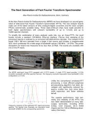
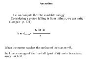
B. Parise et al.: Models of <strong>HDO</strong> <strong>emission</strong> 173of the envelope. Details of these calculations can be found inCHT96. The cooling depends on the abundance of the atomicoxygen, CO and H 2 O, namely the main gas coolants across theenvelope. Hence their abundances are hidden parameters of themodel. The resulting gas temperature tracks the dust temperaturevery closely across the envelope, except where the icymantles evaporate. Because of the injection of large quantitiesof water in the gas phase and the consequent enhancement ofthe gas cooling, the gas and dust (thermally) decouple in a relativelysmall region after the icy mantles evaporation (see alsofor example Maret et al. 2002).Ceccarelli et al. (2000a) and Maret et al. (2002) demonstratedthat the gas temperature differs by no more than 10%<strong>from</strong> the dust temperature, and this occurs in a relatively smallregion just next to where the ices sublimate. There is some uncertaintyabout the water and oxygen abundances in protostars,as derivations of the H 2 O abundance has been obtained in twosources only, IRAS 16293 and NGC 1333–IRAS4 (Ceccarelliet al. 2000a; Maret et al. 2002). However, these uncertainties donot much affect the gas temperature derivation, as in the outerenvelope the gas is cooled mostly by CO 1 , and in the inner envelopeit is cooled by the sublimated water. At the same time, inthe inner region the heating of the gas is dominated by the collisionalde-excitation of the water molecules, photopumped bythe photons emitted by the innermost warm dust (CHT96), sothat the coupling between the dust and gas is always ensured.As a result, the <strong>HDO</strong> computed line intensity is insensitive tothese uncertainties.The original CHT96 model is time-dependent, but the authorsdemonstrated that the physical structure and water chemistrycan be computed at each time independently of the previoushistory, once the luminosity and the <strong>mass</strong> of the protostarare known. The reason for this is that in the outer cold envelopethe abundance of the water is practically constant with time,whereas in the inner warm envelope the water abundance is setby the ice evaporation, except in the very inner regions wherethe temperature exceeds 250 K. Since the sizes of the evaporationregion are set by the temperature and the density profile,for practical applications to real sources one needs to inputthem only. The velocity field is also needed to compute the lineintensity, and this can be derived as well <strong>from</strong> observations.For the standard case described in Sect. 4, we consideredthe case of IRAS 16293, whose velocity, density and temperatureprofiles have been derived by several authors <strong>from</strong> actualobservations. The computations shown in Figs. 2–7 adopted theprofile derived in Ceccarelli et al. (2000a). We also studied thecase of a <strong>low</strong> luminosity source, and we used the velocity, densityand temperature profiles derived for the source L1448 mmby Maret et al. (2004).We approximate the <strong>HDO</strong> abundance profile with a stepfunction. In the outer envelope the <strong>HDO</strong> abundance, x cold ,is relatively <strong>low</strong> and similar to that observed in molecularclouds. In the innermost regions of the envelope, wherethe dust reaches the evaporation temperature T evap , the <strong>HDO</strong>1 The CO lines are optically thick and, therefore, the cooling functiondoes not depend on the CO abundance unless it decreases by afactor of 100 with respect to the standard value.Fig. 1. First energy levels for the <strong>HDO</strong> molecule.abundance, x warm , jumps to larger values. These last three parameters– x cold , x warm and T evap – are the three free parametersof the present modeling, and they will be varied to study theirinfluence on the <strong>HDO</strong> line <strong>emission</strong>.Low-<strong>mass</strong> protostars exhibit energetic molecular outf<strong>low</strong>s,where the gas can be very hot (up to 2000 K, as testified by theH 2 rovibrational <strong>emission</strong> observed in several outf<strong>low</strong>s). Thisgas could in principle contribute to the <strong>HDO</strong> line <strong>emission</strong>, sothat it is important to evaluate whether the outf<strong>low</strong> <strong>emission</strong> canbe comparable to or even larger than the <strong>HDO</strong> <strong>emission</strong> <strong>from</strong>the envelope. From a theoretical point of view, since moleculardeuteration decreases exponentially with increasing gastemperature, the <strong>HDO</strong> abundance is expected to be very <strong>low</strong>in the warm gas of molecular outf<strong>low</strong>s (see also Bergin et al.1999). To support these theoretical expectations, observationsof outf<strong>low</strong>s on several <strong>low</strong>-<strong>mass</strong> protostars have revealed no<strong>HDO</strong> <strong>emission</strong>, at a level at least 10 times fainter than towardsthe protostar (IRAS 16293, Parise et al. 2005; NGC 1333–IRAS2 and IRAS4A, Caux et al. in prep.). We therefore decidedto consider in the present study only the envelope contributionto the <strong>HDO</strong> <strong>emission</strong>.All the line fluxes are computed for a source at a distanceof 160 pc. The model computes the level population of the first34 levels of the <strong>HDO</strong>. The molecular data are <strong>from</strong> the JPL catalogue(http://spec.jpl.nasa.gov/home.html), and thecollisional coefficients are <strong>from</strong> Green (1989), for He-<strong>HDO</strong>collisions between 50 and 500 K, scaled for collision with H 2 .Note that all abundances are reported here with respect to H 2 .3. The <strong>HDO</strong> rotational line spectrum3.1. The energy levels<strong>HDO</strong> is a planar assymetric top molecule. Its dipole liesalong its a and b axies, with dipole moments µ a = 0.657 andµ b = 1.732 Debye (Clough et al. 1973). The al<strong>low</strong>ed transitionsare thus a-type and b-type transitions:∆K a = 0and∆K c = ±1or∆K a = ±1 and∆K c = ±1.
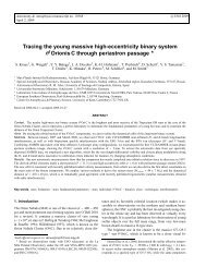
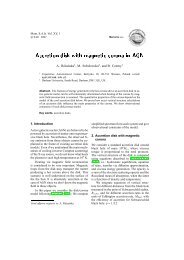
174 B. Parise et al.: Models of <strong>HDO</strong> <strong>emission</strong>Fig. 3. Contribution to the line intensity as function of the distance<strong>from</strong> the central source, for seven <strong>HDO</strong> lines observable<strong>from</strong> the ground (upper panel) and six <strong>from</strong> space based telescopes(<strong>low</strong>er panel).Fig. 2. <strong>HDO</strong> line fluxes predicted for the test caseIRAS 16293−2422 versus the upper level energy of the transition.The upper panel presents the transitions observable <strong>from</strong> theground, the middle panel the transitions observable with HSO/HIFIand the <strong>low</strong>er panel the transitions observable with SOFIA. Thefrequencies of the transitions that are going to be studied in moredetail are indicated in GHz.The first energy levels for <strong>HDO</strong> are presented in Fig. 1.The list of the transitions between the first 34 levels is reportedin Table A.1.3.2. The observing instrumentsWe detail in this section the instruments that operate (or willoperate in the near-future) in the frequency bands interestingfor the <strong>HDO</strong> observations.a) Ground telescopesSeveral ground based facilities al<strong>low</strong> to observe the <strong>HDO</strong> rotationalspectrum transitions.The IRAM (Institute for Millimetre Radioastronomy) 30 mtelescope (Pico Veleta, Spain) operates between 80 and281 GHz.The 15 m JCMT dish (James Clerk Maxwell Telescope,Mauna Kea, Hawaii) observes in the 230, 345, 450, and650 GHz frequency bands. The 800 GHz instrument is nolonger available, but this frequency range will be observablewith APEX.The 10 m CSO dish (Caltech Submillimeter Observatory,Mauna Kea, Hawaii) operates roughly in the same frequencybands as JCMT.The 15 m APEX dish (Atacama Pathfinder EXperiment,Chajnantor, Chile) is being built on the ALMA site. It will al<strong>low</strong>observations in the 230, 345, 650 and 850 GHz bands.b) Airborne instruments: SOFIAThe 2.5 m telescope of the Stratospheric Observatory forInfrared Astronomy, on board a Boeing 747, will be equippedwith several interesting instruments for <strong>HDO</strong> observation.In particular, CASIMIR (CAltech Submillimeter InterstellarMedium Investigations Receiver), will observe in the 500–2100 GHz band and GREAT (German REceiver for Astronomyat Terahertz frequencies) in the 1.5–5 THz.c) The HSO satelliteThe HIFI (Heterodyne Instrument for the Far-Infrared) instrumenton board Herschel Space Observatory (launch plannedin 2007) will al<strong>low</strong> observations in the 480–1250 and 1410–1910 GHz bands.4. Model resultsWe first report the computed <strong>HDO</strong> line spectrum of a test case,to illustrate the general characteristics of the predicted spectrum.Then, in the fol<strong>low</strong>ing paragraphs we discuss thoroughlyhow the <strong>HDO</strong> line spectrum varies with the three free parametersof the model, namely the <strong>HDO</strong> abundance in the outer
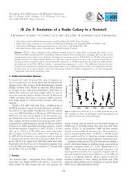
B. Parise et al.: Models of <strong>HDO</strong> <strong>emission</strong> 175Fig. 4. Line intensity as a function of the <strong>HDO</strong> abundance in theouter and inner regions of the envelope, x cold and x warm respectively,for the eight <strong>HDO</strong> transitions at 464, 893, 509, 80, 241, 225, 919and 995 GHz respectively. The first six lines are observable <strong>from</strong> theground, whereas the last two ones will be observable with the Herscheltelescope. Line fluxes are in erg s −1 cm −2 . In these calculations themantle evaporation temperature is 100 K.cold envelope x cold , in the inner warm envelope x warm and theevaporation temperature T evap .The parameters adopted in the test case are reported inTable 1. The values of the hidden parameters are the same asthe test case shown in Ceccarelli et al. (2003) for discussing theH 2 CO line <strong>emission</strong>, and have been derived <strong>from</strong> several observationsof IRAS 16293–2422. The x cold , x warm and T evap parametershave also been derived by the analysis of the <strong>HDO</strong> observationstowards IRAS 16293–2422 (Parise et al. 2005). Inthe fol<strong>low</strong>ing all fluxes are given in erg s −1 cm −2 and are theintegrated <strong>emission</strong> over the entire envelope for a source atFig. 5. Predicted flux for the eight transitions depending on the assumedevaporation temperature and inner <strong>HDO</strong> abundance for anouter abundance x cold fixed to 2 × 10 −10 .160 parsecs. Although the conversion in K km s −1 would havebeen more convenient for the observers, the signal in K km s −1depends on the beam of the telescope used for the observationand how it matches the predicted extent of the <strong>emission</strong>. Wewill give the K km s −1 signal for a few lines, when consideringthe application to observations with ground versus space basedinstruments (Sect. 5).Table A.1 reports the predicted fluxes of the <strong>HDO</strong> lines forthe test case, and Fig. 2 shows the line fluxes as a function ofthe upper energy of the transition.The transitions have been labeled according to the availableobserving facility. The <strong>low</strong>est lying levels are observable <strong>from</strong>the ground and space borne observations become competitivefor upper energies greater than 50 cm −1 .
176 B. Parise et al.: Models of <strong>HDO</strong> <strong>emission</strong>Fig. 6. Predicted flux for the eight transitions depending on the assumedevaporation temperature and outer <strong>HDO</strong> abundance for an innerabundance x warm fixed to 10 −7 .Figure 3 shows the contribution to the <strong>emission</strong> <strong>from</strong> differentshells of the envelope for several transitions with differentupper energy levels, observable with ground-based telescopes(upper panel) or with Herschel-HIFI (<strong>low</strong>er panel). Note thatthe 893 GHz line has been included in the upper panel as it willbe observable with the APEX facility. Some of the lines havebeen observed towards IRAS 16293−2422 using the JCMT andthe IRAM 30 m telescopes (80, 225, 241 and 464 GHz, Pariseet al. 2005). The other ones have been chosen because they arepotentially bright lines (Fig. 2), spanning upper energy levelsup to 150 cm −1 (∼200 K). This figure illustrates that the relativecontribution to the line intensity <strong>from</strong> the inner region(r ≤ 150 AU) increases with increasing upper level energy ofthe transition. While all line intensities are dominated by the<strong>emission</strong> in the inner region (where the abundance is aboutFig. 7. Evaporation temperature dependence in a x warm –x cold diagram.For each transition, the three groups of curves correspond to the contourfor three different values of the line flux. The different curvesfor each group correspond to different values of the evaporation temperature.A narrow group of curves implies that the uncertainty onthe evaporation temperature value will not affect much the estimationof x warm and x cold .3 orders of magnitude higher), the lines with <strong>low</strong> upper levelenergy exhibit a relatively high contribution <strong>from</strong> the cold outerenvelope.4.1. Varying the parametersIn this paragraph, we show how the <strong>HDO</strong> line spectrumchanges varying the three free parameters of the model, namelythe <strong>HDO</strong> abundance in the outer and inner parts of the envelope,x cold and x warm respectively, and the mantle evaporationtemperature T evap .
B. Parise et al.: Models of <strong>HDO</strong> <strong>emission</strong> 177Table 1. Values of the parameters adopted for the test case. The upperpart reports the values of the three free parameters of the model,whereas the <strong>low</strong>er part reports the value of the hidden parameters.Parameterx warmx coldT evapM ⋆Ṁx(CO)x(O)x cold (H 2 O)x warm (H 2 O)Value1 × 10 −71.5 × 10 −10100 K0.8 M ⊙3 × 10 −5 M ⊙ yr −11 × 10 −42.5 × 10 −45 × 10 −73 × 10 −6separate for high x warm . The uncertainty in the evaporation temperaturemostly translates into an uncertainty in x warm .Aremarquablepoint here is again that the 225 GHz <strong>emission</strong> is independentof the temperature.Figure 5 shows that the line fluxes depend much moreon x warm than on T evap . Actually, based in Figs. 5 and 6, it seemsvery difficult to find a way to constrain T evap .However,Fig.7gives a sense of how the two parameters likely can be constrained.The 225 GHz line flux in practice can be used to estimatex warm (Figs. 6 and 7), irrespective of T evap , whereas onecan use, for example, the 464, the 80 and/or the 509 GHz linefluxes to estimate T evap , knowing x warm , <strong>from</strong> Fig. 7. Evidently,it is not possible to easily disentangle the three parameters, butthe above analysis suggests that a full modeling can possiblysucceed.a) x cold and x warmFigure 4 shows the line intensities of eight <strong>HDO</strong> lines(including two lines observable with Herschel-HIFI) for x coldvarying <strong>from</strong> 10 −7 to 10 −12 and x warm varying <strong>from</strong> 10 −5to 10 −10 . As expected, the intensities of the <strong>low</strong>er level transitionsare mostly sensitive to the <strong>emission</strong> <strong>from</strong> the cold partof the envelope, as long as the outer abundance of <strong>HDO</strong> isnot too <strong>low</strong> compared to the inner abundance. For instance the464 GHz line is sensitive to x cold even for inner abundances upto two orders of magnitude larger. On the contrary, the higherthe upper energy, the more the transition becomes dependenton the inner parts of the envelope.The figures also show that the <strong>low</strong> lying lines are much lesssensitive in general to the variation of x warm (a factor 50 at mostvarying x warm by four orders of magnitude) with respect to thehigh lying lines. The latter vary almost linearly with x warm ,sothey are clearly better suited to constrain this parameter thanthe <strong>low</strong> lying lines. On the other hand, x cold is better constrainedby the <strong>low</strong> lying lines, and particularly by the 464 GHz one,which shows the largest variation, nearly 2 orders of magnitudefor a change of x cold of two orders of magnitude.b) T evapFigures 5 and 6 present the predicted fluxes depending onthe evaporation temperature and respectively the inner and theouter abundances. The higher the evaporation temperature, thehigher the inner abundance must be to reproduce the same flux.Indeed, the higher the evaporation temperature, the less extendedthe inner region.The 225 GHz line is mostly independant of the evaporationtemperature in the studied range (Fig 5). Indeed this line hasthe highest upper energy (∼170 K) and is likely to be mostlyexcited in the innermost region of the envelope. Thus it doesnot depend on the evaporation temperature, as long as this temperatureis much <strong>low</strong>er than 170 K, nor on x cold . This line isthus only sensitive to the inner abundance.Another way to understand the dependance of the <strong>emission</strong>versus the evaporation temperature is to plot the regionsspanned when varying the evaporation temperature for a fixed<strong>emission</strong> flux in a x cold –x warm diagram (Fig. 7).As expected, for <strong>low</strong> inner <strong>HDO</strong> abundances, the effect ofthe evaporation temperature is negligible, but curves begin to5. Applications5.1. IRAS 16293–2422In this section we give some practical recipes to derive, to afirst approximation, the values of the parameters of the model<strong>from</strong> actual observations. However, the described method willjust give some approximate estimates of the parameter values,and a full modeling of the source is necessary to derive moreprecise estimates.As a practical example, we will use the data obtained towardsIRAS 16293–2422 (Stark et al. 2004; Parise et al. 2005)and we will derive the approximate values of x cold and x warm .We will then compare these results with those obtained withfull modeling of the <strong>HDO</strong> <strong>emission</strong> <strong>from</strong> this source, as describedin Parise et al. (2005).First, to facilitate the comparison, Table 2 reports the conversionfactor of the line intensity in erg s −1 cm −2 into thevelocity-integrated main beam temperature T mb ∆v observed atthe IRAM and JCMT telescopes respectively, for the five linesobserved towards IRAS 16293−2422 (Parise et al. 2005). Notethat this is simply a conversion table, which does not take intoaccount the convolution of the predicted <strong>emission</strong> with the telescopebeam. This is strictly valid for a point-like source withrespect to the telescope beam sizes. The convolution with thebeam can introduce large factors of difference if the <strong>emission</strong>originates in a region larger than that encompassed by the beamused, as may be the case for <strong>low</strong>-lying lines. In those cases, inorder to use the plots of this article, the observer should takecare to integrate the <strong>emission</strong> over the entire emitting region.Parise et al. (2005) performed a full analysis of the<strong>HDO</strong> <strong>emission</strong> towards IRAS 16293−2422. We describe howeverhow the tools we have given here al<strong>low</strong> us to approximatelyderive the envelope parameters. According to Fig. 7,the <strong>emission</strong> of the 225 GHz line, as well as the upper limiton the x cold derived <strong>from</strong> the 464 GHz line, do not depend onthe evaporation temperature. We can then use Fig. 4 (computedfor an evaporation temperature of 100 K) to derive an upperlimit on x cold <strong>from</strong> the 464 GHz line. Parise et al. (2005) measureda line intensity of 5.5 K km s −1 . Using the conversion factorgiven in Table 2, this corresponds to 2.2×10 −15 erg s −1 cm −2 .We deduce <strong>from</strong> Fig. 4 that x cold is <strong>low</strong>er than a few 10 −10
178 B. Parise et al.: Models of <strong>HDO</strong> <strong>emission</strong>Table 2. Conversion factors of the line intensity in erg s −1 cm −2 into the velocity integrated main beam temperature T mb ∆v observed at theIRAM and JCMT telescopes respectively, for the five lines observed towards IRAS 16293−2422 (Parise et al. 2005). Last column quotes theT mb ∆v observed towards IRAS 16293–2422 (Parise et al. 2005). a Predicted flux <strong>from</strong> the model simply converted into K km s −1 using theconversion factor. b Predicted flux derived using an accurate convolution of the signal with the telescope beam.Transition Frequency Telescope Conversion coeff IRAS 16293–2422(GHz) 1 K km s −1 (T mb ∆v) (Kkm s −1 ) (K km s −1 ) (K km s −1 )(erg s −1 cm −2 ) Conversion a Convolution b Obs c1 1,0 −1 1,1 80.578 IRAM 1.4 × 10 −17 0.19 0.21 0.403 1,2 −2 2,1 225.897 IRAM 4.1 × 10 −17 1.7 1.8 1.72 1,1 −2 1,2 241.561 IRAM 4.4 × 10 −17 1.5 1.5 2.02 2,0 −3 1,3 266.161 IRAM 4.9 × 10 −17 0.20 0.22 0.211 0,1 −0 0,0 464.924 JCMT 4.0 × 10 −16 6.3 5.4 5.5to 10 −9 . The 225 GHz line <strong>emission</strong> then al<strong>low</strong>s us to constrainthe value of x warm (independantly of the evaporation temperature).Indeed, converting the intensity observed by Parise et al.(2005), we find 7 × 10 −17 erg s −1 cm −2 , which with the conditionx cold <strong>low</strong>er than 10 −9 , constrains the abundance of <strong>HDO</strong>in the warm envelope to a value around 10 −7 . The full modelingleads to x warm = (1 ± 0.3) × 10 −7 ,andtoa3σ upper limit onx cold of 10 −9 (Parise et al. 2005).Table 2 compares the predicted fluxes derived <strong>from</strong> themodel by both using the simple conversion flux for a pointlikesource and an accurate convolution with the telescope(IRAM or JCMT) beam, to the observations performed towardsIRAS 16293−2422 (Parise et al. 2005). As expected thesimple conversion works reasonably well for the high-lyinglines, as they originate <strong>from</strong> the small inner envelope (smallenough compared to the beam size to be approximated by apoint). The accuracy of the conversion for the ground line at464 GHz is less good as some of the <strong>emission</strong> originates <strong>from</strong>the outer envelope, which is affected by the convolution of thetelescope beam. Nevertheless the simple conversion is still accurateto 15% because for this testcase, the <strong>HDO</strong> abundance isthree orders of magnitude <strong>low</strong>er in the outer envelope than theinner envelope. The conversion would become critical whenthe abundance in the cold envelope is not <strong>low</strong> compared to thewarm contribution.The plots of Figs. 4–6 can be used with single dish observationswithout the need for convolution, for the signal, originatingin the warm part of the envelope, is likely to be encompassedby the telescope beam.5.2. The <strong>low</strong> luminosity source case: L1448 mmThe previous predictions are of course dependent on the physicalstructure considered for the source. As an example, we alsoplotted the contours for a <strong>low</strong>-luminosity source, L1448 mm,for which physical characteristics can be found in Jørgensenet al. (2002) or Maret et al. (2004). The results are presented inAppendix B. The contours roughly look the same, except thatthe <strong>emission</strong> is weaker in L1448 mm.5.3. Are space-based telescope observations towards<strong>low</strong>-<strong>mass</strong> protostars necessary?We saw in the previous sections that the observation of thestudied lines <strong>from</strong> the ground al<strong>low</strong>s one to perfectly constrainthe inner <strong>HDO</strong> abundance. However, the outer <strong>HDO</strong> abundancecan only be constrained using <strong>low</strong>er energy transitions.Among the studied lines, only the 464 GHz can provide, insome specific conditions (namely when the outer abundanceis not too <strong>low</strong> compared with the inner abundance) some informationon x cold . Unfortunately, the transitions that will be observable<strong>from</strong> space are at higher energy (see Fig. 2). They willhence only provide information on the inner abundance, whichis already correctly constrained with the transitions observedwith ground-based telescopes. Moreover observations <strong>from</strong> theground, when possible, have to be preferred owing to the betterspatial resolution. Table 3 lists the integration time required toobserve some selected transitions with a peak signal to noiseof 5, at a resolution of 0.5 km s −1 , with the various instrumentsIRAM 30 m, JCMT and HSO/HIFI. Note that in each case, onlyone receiver was assumed (single polarization mode) so that theintegration time could in principle be <strong>low</strong>ered by a factor of √ 2if the observations are carried out in double polarization mode.An average of 2 mm of water vapor has been assumed at theIRAM 30 m, where the average elevation of the source is 25 ◦and 70 ◦ respectively for IRAS 16293 and L1448 mm. Weatherband 2 was assumed at JCMT, with a zenith angle of 40 and20 respectively. An efficiency factor of 0.125 was assumed forHIFI, as predicted in chopping mode.These predictions show that for sources as bright asIRAS 16293, observations can be carried out <strong>from</strong> the ground,and no Herschel time is thus necessary. But in the case of a<strong>low</strong>-luminosity protostar, where the same abundance profileof <strong>HDO</strong> was assumed, integration times start to become prohibitive<strong>from</strong> the ground. The 225 and 241 GHz lines mayremain observable, using double polarisation receivers. Notethat the integration time required with HIFI is prohibitive, theonly reasonable transition being the 995 GHz. Thus, in thecase of <strong>low</strong>-luminosity source, neither ground-based telescopesnor HSO/HIFI seem to be sensitive enough. The interferometerALMA might provide in this case the only possibility ofconstraining the <strong>HDO</strong> abundance.
B. Parise et al.: Models of <strong>HDO</strong> <strong>emission</strong> 179Table 3. Integration time required to detect the <strong>HDO</strong> lines with a peaksignal over noise of 5 (see text). Note that only one receiver was assumed,so in principle those times can be <strong>low</strong>ered by a factor √ 2byusing a double polarization setup.Transition IRAM 30 m JCMT HSO/HIFIIRAS 16293 (30 L ⊙ )80 GHz 5.6 h225 GHz 15 min241 GHz 30 min464 GHz 29 min490 GHz 21 min 7 min509 GHz 34 h ∗ 104 min893 GHz 16 min995 GHz 5 minL1448 mm (5 L ⊙ )80 GHz 3500 h225 GHz 110 h241 GHz 227 h464 GHz 185 h490 GHz 132 h 73 h509 GHz 1562 h ∗ 471 h893 GHz 59 h995 GHz 16 h∗ The sensibility drops on the edge of the band.6. ConclusionsWe reported theoretical predictions of the deuterated water line<strong>emission</strong> <strong>from</strong> the <strong>envelopes</strong> of <strong>low</strong> <strong>mass</strong> protostars. In thisstudy, we have focused only on the envelope <strong>emission</strong>, neglectingany <strong>HDO</strong> <strong>emission</strong> <strong>from</strong> the outf<strong>low</strong>s, which is expected tobe of minor importance based on theoretical and observationalarguments. We have shown that the simultaneous observationsof appropriately selected transitions permit us to approximatelyconstrain the <strong>HDO</strong> abundance in the outer cold and inner warmparts of the envelope. The uncertainty on the evaporation temperaturemostly translates into an uncertainty on the inner abundance.The inner abundance can however be quite accuratelydetermined using the 225 GHz line for which the <strong>emission</strong> hasbeen shown to be independent of the evaporation temperature.The most important result of the present study is that,for bright <strong>low</strong>-<strong>mass</strong> protostars (L > 10 L ⊙ ), observationsfeasible <strong>from</strong> ground telescopes are sufficient to constrainthe <strong>HDO</strong> abundance profile and evaporation temperature,and no HSO observations are required. In the case of <strong>low</strong>luminosityprotostars (L < 10 L ⊙ ), both present ground-basedtelescopes and HSO seem to lack the sensitivity necessary toobserve <strong>HDO</strong> lines in a reasonable integration time. The <strong>HDO</strong>abundance profile and evaporation temperature will probablybe directly constrained by future high resolution observationswith the large sub/millimeter interferometer ALMA.Acknowledgements. We wish to thank the anonymous referee for veryuseful comments that helped to improve this article.ReferencesBergin, E. A., Neufeld, D. A., & Melnick, G. J. 1999, ApJ, 510, L145Bottinelli, S., Ceccarelli, C., Lefloch, B., et al. 2004a, ApJ, 615, 354Bottinelli, S., Ceccarelli, C., Neri, R., et al. 2004b, ApJ, 617, L69Caux, E., et al. in prep., A&ACazaux, S., Tielens, A. G. G. M., Ceccarelli, C., et al. 2003, ApJ, 593,L51Ceccarelli, C., Hollenbach, D. J., & Tielens, A. G. G. M. 1996, ApJ,471, 400Ceccarelli, C., Castets, A., Loinard, L., Caux, E., & Tielens, A. G.G. M. 1998, A&A, 338, L43Ceccarelli, C., Castets, A., Caux, E., et al. 2000a, A&A, 355, 1129Ceccarelli, C., Loinard, L., Castets, A., Tielens, A. G. G. M., & Caux,E. 2000b, A&A, 357, L9Ceccarelli, C., Maret, S., Tielens, A. G. G. M., Castets, A., & Caux,E. 2003, A&A, 410, 587Clough, S. A., Beers, Y., Klein, G. P., & Rothman, L. S. 1973, J. Chem.Phys., 59, 2254Dartois, E., Thi, W.-F., Geballe, T. R., et al. 2003, A&A, 399, 1009Gibb, E. L., Whittet, D. C. B., Boogert, A. C. A., & Tielens,A. G. G. M. 2004, ApJS, 151, 35Green, S. 1989, ApJS, 70, 813Jørgensen, J. K., Schöier, F. L., & van Dishoeck, E. F. 2002, A&A,389, 908Kuan, Y., Huang, H., Charnley, S. B., et al. 2004, ApJ, 616, L27Lis, D. C., Roueff, E., Gérin, M., et al. 2002, ApJ, 571, L55Maret, S., Ceccarelli, C., Caux, E., Tielens, A. G. G. M., & Castets,A. 2002, A&A, 395, 573Maret, S., Ceccarelli, C., Caux, E., et al. 2004, A&A, 416, 577Maret, S., Ceccarelli, C., Tielens, A., et al. 2005, A&A, submittedNeufeld, D. A., & Kaufman, M. J. 1993, ApJ, 418, 263Parise, B., Ceccarelli, C., Tielens, A. G. G. M., et al. 2002, A&A, 393,L49Parise, B., Simon, T., Caux, E., et al. 2003, A&A, 410, 897Parise, B., Castets, A., Herbst, E., et al. 2004, A&A, 416, 159Parise, B., Caux, E., Castets, A., et al. 2005, A&A, 431, 547Roberts, H., & Millar, T. J. 2000, A&A, 361, 388Roberts, H., Herbst, E., & Millar, T. J. 2003, ApJ, 591, L41Rodgers, S. D., & Charnley, S. B. 2003, ApJ, 585, 355Schöier, F. L., Jørgensen, J. K., van Dishoeck, E. F., & Blake, G. A.2002, A&A, 390, 1001Schöier, F. L., Jørgensen, J. K., van Dishoeck, E. F., & Blake, G. A.2004, A&A, 418, 185Shu, F. H. 1977, ApJ, 214, 488Stark, R., Sandell, G., Beck, S. C., et al. 2004, ApJ, 608, 341van der Tak, F. F. S., Schilke, P., Müller, H. S. P., et al. 2002, A&A,388, L53Vastel, C., Phillips, T. G., Ceccarelli, C., & Pearson, J. 2003, ApJ, 593,L97
B. Parise et al.: Models of <strong>HDO</strong> <strong>emission</strong>, Online Material p 1Online Material
Appendix A: The predicted fluxes for the test caseof IRAS 16293−2422Table A.1. Predicted fluxes for the IRAS 16293−2422 test case.B. Parise et al.: Models of <strong>HDO</strong> <strong>emission</strong>, Online Material p 2Table A.1. continued.Transition Freq. E up A ul Line flux(GHz) (cm −1 ) (s −1 ) (ergs −1 cm −2 )3 3,0 − 3 3,1 0.824671 233.050 2.12 × 10 −12 2.6 × 10 −285 0,5 − 4 2,2 3.29676 221.946 4.34 × 10 −13 3.2 × 10 −274 3,1 − 4 3,2 5.70278 295.677 4.17 × 10 −10 2.1 × 10 −252 2,0 − 2 2,1 10.2782 109.269 3.63 × 10 −9 1.3 × 10 −223 2,1 − 4 1,4 20.4600 157.064 9.58 × 10 −9 2.6 × 10 −225 3,2 − 5 3,3 22.3077 374.409 1.64 × 10 −8 1.7 × 10 −233 2,1 − 3 2,2 50.2363 157.064 2.08 × 10 −7 1.8 × 10 −204 3,1 − 5 2,4 61.1859 295.676 2.66 × 10 −7 1.3 × 10 −216 0,6 − 5 2,3 69.5506 306.312 3.48 × 10 −9 1.2 × 10 −221 1,0 − 1 1,1 80.5783 32.4939 1.32 × 10 −6 2.7 × 10 −185 1,5 − 4 2,2 120.778 225.862 1.33 × 10 −6 3.8 × 10 −196 1,6 − 5 2,3 138.531 308.612 1.43 × 10 −6 9.7 × 10 −204 2,2 − 4 2,3 143.727 221.832 2.80 × 10 −6 2.6 × 10 −193 2,1 − 4 0,4 207.111 157.060 1.14 × 10 −7 4.2 × 10 −203 1,2 − 2 2,1 225.897 116.456 1.31 × 10 −5 7.0 × 10 −172 1,1 − 2 1,2 241.562 66.1781 1.18 × 10 −5 6.5 × 10 −175 2,3 − 4 3,2 255.050 303.989 1.78 × 10 −5 1.0 × 10 −182 2,0 − 3 1,3 266.161 109.262 1.75 × 10 −5 1.0 × 10 −175 2,3 − 5 2,4 310.533 303.987 1.78 × 10 −5 1.1 × 10 −186 2,5 − 5 3,2 313.751 384.867 3.75 × 10 −5 1.1 × 10 −183 3,1 − 4 2,2 335.396 233.016 2.61 × 10 −5 1.2 × 10 −185 3,2 − 6 1,5 356.836 374.402 3.53 × 10 −7 5.8 × 10 −211 0,1 − 0 0,0 464.925 15.4975 1.69 × 10 −4 2.5 × 10 −153 3,0 − 4 2,3 479.947 233.039 7.28 × 10 −5 4.6 × 10 −183 1,2 − 3 1,3 481.780 116.449 4.74 × 10 −5 2.6 × 10 −162 0,2 − 1 1,1 490.597 46.1612 5.25 × 10 −4 6.4 × 10 −151 1,0 − 1 0,1 509.292 32.4844 2.32 × 10 −3 1.8 × 10 −152 2,0 − 3 0,3 537.793 109.256 9.94 × 10 −7 1.8 × 10 −182 1,1 − 2 0,2 599.927 66.1706 3.45 × 10 −3 2.9 × 10 −153 1,2 − 3 0,3 753.411 116.444 5.90 × 10 −3 4.2 × 10 −154 1,3 − 4 1,4 797.487 182.965 1.31 × 10 −4 3.2 × 10 −164 1,3 − 3 2,2 827.263 182.964 1.28 × 10 −3 4.2 × 10 −152 1,2 − 1 1,1 848.962 58.1067 9.27 × 10 −4 1.0 × 10 −141 1,1 − 0 0,0 893.639 29.7880 8.35 × 10 −3 1.1 × 10 −144 3,1 − 5 1,4 912.605 295.656 2.74 × 10 −6 2.1 × 10 −192 0,2 − 1 0,1 919.311 46.1517 1.56 × 10 −3 1.5 × 10 −144 1,3 − 4 0,4 984.138 182.961 1.07 × 10 −2 5.4 × 10 −153 0,3 − 2 1,2 995.411 91.3064 7.04 × 10 −3 2.3 × 10 −142 1,1 − 1 1,0 1009.94 66.1608 1.56 × 10 −3 1.5 × 10 −145 2,3 − 5 1,4 1161.95 303.968 2.19 × 10 −2 1.6 × 10 −154 2,2 − 4 1,3 1164.77 221.809 2.00 × 10 −2 3.0 × 10 −155 1,4 − 5 1,5 1180.32 265.208 2.97 × 10 −4 2.3 × 10 −163 2,1 − 3 1,2 1217.26 157.036 1.89 × 10 −2 4.4 × 10 −153 1,3 − 2 1,2 1267.04 100.361 3.91 × 10 −3 2.8 × 10 −142 1,2 − 1 0,1 1277.68 58.0972 2.19 × 10 −2 3.1 × 10 −142 2,0 − 2 1,1 1291.64 109.239 1.59 × 10 −2 6.3 × 10 −155 1,4 − 5 0,5 1297.81 265.206 1.97 × 10 −2 5.4 × 10 −153 0,3 − 2 0,2 1353.78 91.2989 5.30 × 10 −3 3.6 × 10 −14Transition Freq. E up A ul Line flux(GHz) (cm −1 ) (s −1 ) (ergs −1 cm −2 )3 2,1 − 2 2,0 1432.88 157.032 3.54 × 10 −3 7.2 × 10 −155 1,4 − 4 2,3 1444.83 265.202 1.02 × 10 −2 8.6 × 10 −154 0,4 − 3 1,3 1491.93 150.121 3.07 × 10 −2 4.0 × 10 −143 3,0 − 4 1,3 1500.99 233.016 3.67 × 10 −6 7.9 × 10 −193 1,2 − 2 1,1 1507.26 116.426 6.58 × 10 −3 3.6 × 10 −142 2,1 − 2 1,2 1522.93 108.890 2.06 × 10 −2 1.1 × 10 −146 1,5 − 6 1,6 1615.63 362.469 5.84 × 10 −4 1.5 × 10 −163 1,3 − 2 0,2 1625.41 100.353 4.49 × 10 −2 5.4 × 10 −143 2,2 − 3 1,3 1648.80 155.350 3.08 × 10 −2 1.1 × 10 −144 1,4 − 3 1,3 1678.58 156.343 9.92 × 10 −3 4.1 × 10 −146 1,5 − 6 0,6 1684.61 362.468 3.47 × 10 −2 4.3 × 10 −154 0,4 − 3 0,3 1763.56 150.115 1.20 × 10 −2 5.0 × 10 −144 2,3 − 4 1,4 1818.53 217.000 4.12 × 10 −2 1.0 × 10 −144 2,3 − 3 2,2 1848.31 216.999 1.06 × 10 −2 1.1 × 10 −144 3,2 − 3 3,1 1872.61 295.443 6.46 × 10 −3 9.6 × 10 −164 3,1 − 3 3,0 1877.49 295.634 6.51 × 10 −3 9.7 × 10 −162 2,1 − 2 0,2 1881.29 108.883 1.21 × 10 −4 7.6 × 10 −163 2,2 − 3 0,3 1920.43 155.344 3.04 × 10 −4 1.1 × 10 −154 2,2 − 3 2,1 1941.80 221.791 1.23 × 10 −2 1.1 × 10 −145 3,3 − 6 1,6 1950.15 373.620 1.11 × 10 −5 9.4 × 10 −195 3,3 − 6 1,6 1950.15 373.620 1.11 × 10 −5 6.3 × 10 −145 0,5 − 4 1,4 1965.55 221.900 8.28 × 10 −2 4.2 × 10 −144 1,3 − 3 1,2 1994.29 182.937 1.66 × 10 −2 4.0 × 10 −144 2,3 − 4 0,4 2005.18 216.995 5.46 × 10 −4 8.0 × 10 −165 3,3 − 6 0,6 2019.13 373.618 4.52 × 10 −4 3.9 × 10 −175 2,4 − 5 1,5 2031.74 293.589 5.43 × 10 −2 7.9 × 10 −156 1,5 − 5 2,4 2064.69 362.459 4.07 × 10 −2 9.5 × 10 −155 1,5 − 4 1,4 2083.04 225.816 1.98 × 10 −2 3.4 × 10 −144 3,2 − 5 1,5 2087.23 295.438 9.50 × 10 −6 1.6 × 10 −185 3,2 − 5 2,3 2110.99 374.360 8.12 × 10 −2 3.0 × 10 −155 2,4 − 5 0,5 2149.22 293.587 8.51 × 10 −4 4.5 × 10 −165 0,5 − 4 0,4 2152.20 221.896 2.23 × 10 −2 4.0 × 10 −144 3,2 − 5 0,5 2204.71 295.436 3.39 × 10 −4 6.0 × 10 −174 3,1 − 4 2,2 2213.71 295.626 7.73 × 10 −2 5.3 × 10 −155 1,5 − 4 0,4 2269.69 225.812 1.36 × 10 −1 5.3 × 10 −143 3,0 − 3 2,1 2278.02 232.998 5.79 × 10 −2 7.5 × 10 −156 2,5 − 6 1,6 2286.21 384.822 7.15 × 10 −2 5.4 × 10 −152 2,1 − 1 1,0 2291.31 108.873 1.26 × 10 −1 3.9 × 10 −145 2,4 − 4 2,3 2296.25 293.583 2.32 × 10 −2 9.6 × 10 −153 3,1 − 4 1,4 2297.65 232.970 5.62 × 10 −6 1.8 × 10 −183 3,1 − 3 2,2 2327.43 232.970 6.09 × 10 −2 7.9 × 10 −155 3,3 − 4 3,2 2343.74 373.612 1.89 × 10 −2 1.7 × 10 −154 3,2 − 4 2,3 2351.73 295.432 8.88 × 10 −2 6.0 × 10 −156 2,5 − 6 0,6 2355.19 384.820 1.23 × 10 −3 2.4 × 10 −165 3,2 − 4 3,1 2360.34 374.355 1.93 × 10 −2 1.8 × 10 −152 2,0 − 1 1,1 2382.17 109.214 1.29 × 10 −1 4.4 × 10 −145 3,3 − 5 2,4 2399.22 373.610 1.07 × 10 −1 4.2 × 10 −156 0,6 − 5 1,5 2411.83 306.258 1.70 × 10 −1 3.3 × 10 −145 2,3 − 4 2,2 2463.05 303.938 2.89 × 10 −2 1.0 × 10 −145 1,4 − 4 1,3 2465.87 265.179 3.27 × 10 −2 2.7 × 10 −146 1,6 − 5 1,5 2480.81 308.558 3.44 × 10 −2 2.0 × 10 −143 3,1 − 4 0,4 2484.30 232.966 1.56 × 10 −4 5.1 × 10 −176 0,6 − 5 0,5 2529.31 306.256 3.67 × 10 −2 2.3 × 10 −146 1,6 − 5 0,5 2598.29 308.556 2.18 × 10 −1 3.7 × 10 −143 2,2 − 2 1,1 2674.28 155.327 1.59 × 10 −1 4.8 × 10 −14
B. Parise et al.: Models of <strong>HDO</strong> <strong>emission</strong>, Online Material p 3Table A.1. continued.Transition Freq. E up A ul Line flux(GHz) (cm −1 ) (s −1 ) (ergs −1 cm −2 )6 2,5 − 5 2,4 2735.28 384.812 4.22 × 10 −2 6.9 × 10 −152 2,0 − 1 0,1 2810.88 109.204 2.43 × 10 −4 2.2 × 10 −156 1,5 − 5 1,4 2916.11 362.440 5.53 × 10 −2 1.5 × 10 −143 2,1 − 2 1,2 2966.08 156.995 1.62 × 10 −1 5.8 × 10 −144 2,3 − 3 1,2 3015.33 216.972 2.05 × 10 −1 4.6 × 10 −145 3,3 − 5 1,4 3250.64 373.591 7.43 × 10 −4 9.9 × 10 −175 2,4 − 4 1,3 3317.29 293.559 2.63 × 10 −1 3.6 × 10 −143 2,1 − 2 0,2 3324.45 156.988 8.77 × 10 −4 4.6 × 10 −154 3,2 − 4 1,3 3372.77 295.409 4.06 × 10 −4 1.0 × 10 −163 3,1 − 3 1,2 3494.45 232.943 1.57 × 10 −4 6.6 × 10 −176 2,5 − 5 1,4 3586.70 384.793 3.37 × 10 −1 2.4 × 10 −144 2,2 − 3 1,3 3640.83 221.751 1.96 × 10 −1 5.9 × 10 −143 3,1 − 2 2,0 3710.07 232.938 6.26 × 10 −1 3.6 × 10 −143 3,0 − 2 2,1 3721.17 232.965 6.30 × 10 −1 3.5 × 10 −144 2,2 − 3 0,3 3912.47 221.746 1.99 × 10 −3 4.4 × 10 −153 3,0 − 3 1,3 3977.05 232.958 1.37 × 10 −4 5.8 × 10 −174 3,2 − 3 2,1 4149.80 295.391 6.85 × 10 −1 3.4 × 10 −144 3,1 − 4 1,4 4175.96 295.581 3.25 × 10 −4 8.7 × 10 −174 3,1 − 3 2,2 4205.74 295.580 7.02 × 10 −1 3.3 × 10 −143 3,0 − 3 0,3 4248.69 232.953 2.23 × 10 −3 8.7 × 10 −164 3,1 − 4 0,4 4362.61 295.576 8.17 × 10 −3 2.0 × 10 −155 2,3 − 4 1,4 4425.31 303.892 2.21 × 10 −1 4.9 × 10 −145 3,2 − 5 1,5 4453.27 374.306 5.25 × 10 −4 8.5 × 10 −175 3,3 − 4 2,2 4551.74 373.561 7.54 × 10 −1 3.0 × 10 −145 3,2 − 5 0,5 4570.75 374.304 1.73 × 10 −2 2.5 × 10 −155 2,3 − 4 0,4 4611.96 303.888 3.35 × 10 −3 2.6 × 10 −155 3,2 − 4 2,3 4717.77 374.300 7.96 × 10 −1 2.9 × 10 −143 3,0 − 2 1,1 5002.54 232.935 4.68 × 10 −4 1.8 × 10 −163 3,1 − 2 1,2 5243.27 232.902 4.16 × 10 −4 1.5 × 10 −164 3,1 − 3 1,2 5372.76 295.553 1.32 × 10 −3 3.3 × 10 −163 3,1 − 2 0,2 5601.64 232.894 3.24 × 10 −3 7.3 × 10 −165 3,2 − 4 1,3 5738.82 374.277 2.85 × 10 −3 4.7 × 10 −164 3,2 − 3 1,3 5848.84 295.351 1.02 × 10 −3 1.8 × 10 −164 3,2 − 3 0,3 6120.47 295.346 1.56 × 10 −2 1.5 × 10 −155 3,3 − 4 1,4 6514.00 373.515 1.83 × 10 −3 1.8 × 10 −165 3,3 − 4 0,4 6700.65 373.511 4.38 × 10 −2 2.7 × 10 −15
Appendix B: The <strong>low</strong> luminosity case: L1448 mmWe present here the results for the case of the <strong>low</strong>-luminositysource L1448 mm. The density and temperature profiles wherederived by Jørgensen et al. (2002).B. Parise et al.: Models of <strong>HDO</strong> <strong>emission</strong>, Online Material p 4Fig. B.1. <strong>HDO</strong> line fluxes predicted for the case of the <strong>low</strong>-luminositysource L1448 mm, for an assumed <strong>HDO</strong> abundance of 10 −10 and 10 −7in the cold and warm parts of the envelope respectively. The upperpanel presents the transitions observable <strong>from</strong> the ground, the middlepanel the transitions observable with HSO/HIFI and the <strong>low</strong>er panelthe transitions observable with SOFIA. The frequencies of the transitionsthat are going to be studied in more detail are indicated in GHz.Fig. B.2. Line intensity as a function of the <strong>HDO</strong> abundance in theouter and inner regions of the envelope, x cold and x warm respectively,for the eight <strong>HDO</strong> transitions at 464, 893, 509, 80, 241, 225, 919 and995 GHz respectively towards the <strong>low</strong>-luminosity source L1448 mm.Line fluxes are in erg s −1 cm −2 . In these calculations the mantle evaporationtemperature is 100 K.
Fig. B.3. Line intensity as a function of the inner <strong>HDO</strong> abundanceand the evaporation temperature, for the eight <strong>HDO</strong> transitions at 464,893, 509, 80, 241, 225, 919 and 995 GHz respectively towards the<strong>low</strong>-luminosity source L1448 mm. Line fluxes are in erg s −1 cm −2 .Inthese calculations the outer <strong>HDO</strong> abundance is 10 −10 .B. Parise et al.: Models of <strong>HDO</strong> <strong>emission</strong>, Online Material p 5