INVERTED MICROSCOPE - MRC
INVERTED MICROSCOPE - MRC
INVERTED MICROSCOPE - MRC
- No tags were found...

You also want an ePaper? Increase the reach of your titles
YUMPU automatically turns print PDFs into web optimized ePapers that Google loves.
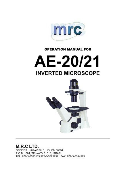
OPERATION MANUAL FORAE-20/21<strong>INVERTED</strong> <strong>MICROSCOPE</strong>M.R.C LTD.OFFICES: HAGAVISH 3, HOLON 58394P.O.B. 1684, TEL-AVIV 61016, ISRAELTEL: 972-3-5593105,972-3-5595252 FAX: 972-3-5594529
We are constantly endeavouring to improve our instruments and to adapt them to therequirements of modern research techniques and testing methods. This involves modification tothe mechanical structure and optical design of our instruments.Therefore, all descriptions and illustrations in this instruction manual, including allspecifications are subject to change without notice.1
TABLE OF CONTENTSSectionPageI. Nomenclature ………………………………………………………………………… 3II. Setting-up the instrument …………………………………………………………… 5III. Assembling the Microscope …………………………………………………………… 61. Installing the Lamp ………………………………………………………………… 62. Halogen Lamp ……………………………………………………………………… 63. Filter Holder ………………………………………………………………………… 64. Mounting the Condenser …………………………………………………………… 75. Installing the Objectives …………………………………………………………… 76. Mechanical Stage ………………………………………………………………… 77. Mounting the Eyepieces …………………………………………………………… 7IV. Microscopic Procedure ……………………………………………………………… 81. Interpupillary Distance Adjustment ………………………………………………… 82. Diopter Adjustment ………………………………………………………………… 83. Brightfield Microscopy …………………………………………………………… 84. Phase-Contrast Microscopy ………………………………………………………… 9V. Photomicrographic Procedure ……………………………………………………… 10VI. Troubleshooting Table ………………………………………………………………… 11VII. Care and Maintenance ………………………………………………………………… 121. Lenses and Filters …………………………………………………………………… 122. Cleaning of Painted or Plastic Components………………………………………… 123. When Not in Use …………………………………………………………………… 134. Warning Lable …………………………………………………………………… 132
I. NomenclatureModel AE203
Model AE214
II. Setting-up the InstrumentWorking Environment• The location should be free from dust, moisture, chemical vapours and from mechanicalvibrations.• Do not situate the instrument in a warm and/or humid environment.• Locate the instrument where the operator’s line of vision is not directed towards a window, alamp or a well-lit bright wall. The quality of the viewed image from the microscope willdeteriorate where there is significant ambient light.Specifications• Magnification Ratio : 40X-400X• Eyepiece : Objective field φ20• Objectives :Maganification N.A. W.D.4X 0.1 15.2PH10X 0.25 6.3PH20X 0.4 5.540X 0.6 2.1• Condenser : 1. N.A. 0.3 / W.D. 72mm• LED : 6V / 30W Halogen Illumination Adjustable• Electrical Specifications:• Input : 90-240VAC, 35W, 50-60HZOutput : 12V, 30W• Fuse : T2.5AL250V (If the orginal fuese is damaged, please replace a new one with samespecification.5
Operating environment• Indoor use• Altitude:Max 2000 meters• Ambient temperature: 15°C to 35°C• Maximum relative humidity: Relative Humidity of not more than 75%• Supply voltage fluctuations: Not to exceed ±10% of the normal voltage• Pollution degree: 2(in according with IEC60664)Installation/Overvoltage category: (in according with IEC60664)• Air Pressure of 75kPa to 106 kPa• No hoar frost, dew, percolating water, rain6
III. Assembling the Microscope Input Voltage• Automatic voltage selection works with electrical outlets worldwide. However, always use apower cord that is rated for the voltage used in your area and that has been approved to meetlocal safety standards. Using the wrong power cord could cause fire or equipment damage.• In case of using the extension cord, use only the power supply cord with the PE(protective earth) wire.• In order to prevent electric shock, always turn the power switch on the power supply off beforeconnecting the power cord.1. Installing the Lamp• In order to prevent electric shock always turn the power switch off and unplug the power cordbefore replacing the lamp.• To remove lamphouse cover, press down lightly and rotate counter clockwise.• Firmly insert the lamp into the socket pinholes until it reaches the limit, be careful not to tiltthe lamp when mounting.• When installing the lamp, do not touch the glass surface of the lamp with bare fingers. Doingso will cause fingerprints, grease, etc., to burn onto the lamp surface, reducing the illuminationprovided by the lamp. If surface is contaminated, wipe it clean using lens tissue.• Return lamphouse cover to original position and rotate clockwise to lock into place. Themodel name marked on the cover should face the user.2. Halogen Lamp• The quartz halogen lamp, used as a light source, has higher luminance and colour temperaturethan conventional tungsten lamps. The luminance is approximately four times brighter.• As long as the lamp voltage is kept constant, the halogen lamp maintains the same level ofbrightness and colour temperature regardless of whether it is new or nearing the end of its life.3. Filter Holder• Insert filter holder in opening located under the lamphouse7
IV. Microscopic Procedure1. Interpupillary Distance Adjustment• Before adjusting the interpupillary distance, bring a specimen into focus using the 10xobjective.• Adjust the interpupillary distance so that both the right and left field of view become one.• This adjustment will enable the user to observe the specimen with both eyes.2. Diopter Adjustment• Diopter adjustment compensates for the differences in vision between the left and right eyes. Inaddition to making observation through both eyes easier, this adjustment also reduces theextent to which focusing is lost when the objective magnification is changed. In particular, thisoccurs when a low magnification objective is used.• The left eyepiece has a separate focusing provision to compensate for slight differences in thefocusing of each eye.• Using the right eye only and viewing through the right-hand eyepiece, adjust the focus with themicroscope fine or coarse adjustment until the image of the specimen is at its sharpest.• Using the left eye only and viewing through the left-hand eyepiece with its independentdiopter-focusing ring, focus until the specimen image is at its sharpest.• The microscope should now be ready binocular viewing.3. Brightfield Microscopy• Set the Phase annular diaphragm slider in centre position (O).• Bring the specimen image into focus.• Adjust the opening of the field of view diaphragm, for normal observation the size of thediaphragm should be just outside the edge of the field of view.• The condenser aperture diaphragm is provided for adjusting the numerical aperture (N.A.) ofthe illuminating system of the microscope. It is important because it determines the resolutionof the image, contrast, depth of focus and brightness.• Stopping down the aperture diaphragm will lower the resolution and brightness but increasethe contrast and depth of focus. By stopping down the N.A. of the condenser to 2/3 of the N.A.of the objective, a good image of suitable contrast will be obtained.9
4. Phase-Contrast MicroscopyFully open the aperture diaphragmMove the aperture diaphragm lever on the condenser to fully open position. Always fully open theaperture diaphragm for phase contrast microscopy. If aperture diaphragm is closed, it will obstructthe annular diaphragm and the phase contrast effect cannot be obtained.• Phase contrast objectives are labelled “Ph”: Ph1; Ph2; Ph3.• For phase contrast microscopy, be sure to use the annular diaphragm that has the same symbolas the objective, despite of the magnification of the objective.• Fully open the aperture diaphragm.• Bring the 10x (Ph1) objective into optical path.• Position the Phase annular diaphragm slider to 10 –20.• Set slider to 40 when using 40x (Ph3) objective.• Remove either eyepiece from the eyepiece tube and insert the phase centering telescopeinstead. Rotate the eyepiece of the centering telescope to focus on both the phase plate imageof the objective and the annular diaphragm image of the phase slider.• If the objective phase plate and the annular of the slider do not coincide, use the two hexagonalscrewdrivers supplied with the microscope to bring the slider annular ring to the centre of thephase plate, so that the image of the annular diaphragm is concentric with the phase plateimage.• If the slider annular ring image is diverged from the phase plate image in the objective, a lowphase contrast image will result.• For phase contrast microscopy at the maximum contrast, use GIF (Green interference filter) inthe optical path.10
V. Photomicrographic Procedure (Model AE21 Only)• The optical path selector lever can be used to set the optical path to either the Binocular tube100:0 or Binocular tube / vertical tube 20:80 (observation: photo).• Before starting photomicrography, check the following:• The condenser is centered.• The condenser annular diaphragm is centred.• The field of view diaphragm is stopped down to slightly just outside the edge of the field of view.• For photomicrographic procedures, refer to the manual of the specific camera being used.Filter selectionFilter holder holds up to two filtersFilter typeDiffuserGIF (Green interference) 546nmNCB (Neutral Colour Balance) BlueProcedureTo be used in all casesFor phase contrast microscopy and forimproving the contrast in monochromephotomicrographyFor routine microscopy and colourphotomicrographyNever attempt either of the following actions, since doing so will damage the focusingmechanism:• Rotate the left and right knob while holding the other.• Turning the coarse and fine focus knobs further than their limit.11
VI. Troubleshooting TableAs you use your microscope, you may occasionally experience a problem. The troubleshootingtable below contains the most frequently encountered problems and their possible causes.Optical and Operating ProblemsProblemVignetting or uneven brightness in thefield of view or field of view onlypartially visibleDust or dirt in field of viewImage quality:No image under phase contrast or detailscannot be viewedEye strain or fatigueImage quality:No image under phase contrast or detailscannot be viewedPossible CauseLamp not installed properlyFilter slider in intermediate positionPhase slider not in click-stop positionIncorrect condenser mountingAperture diaphragm closed too farRevolving nosepiece not clicked into positionOptical path selector lever in intermediate position(Mod. AE21 only)Aperture diaphragm closed too farDust or dirt on specimen’s surfaceBrightfield objective being usedPhase annular diaphragm not in optical pathPhase annular diaphragm and objective phasesymbol do not matchSlider annular ring image has moved away from theobjective phase plate imageThickness of specimen holder is outside thecompensating range of objectiveInterpupillary distance not adjustedDiopter adjustment not madeInadequate illuminationField of view of left and right eyepiece differBrightfield objective being usedPhase annular diaphragm not in optical pathPhase annular diaphragm and objective phasesymbol do not matchSlider annular ring image has moved away from theobjective phase plate image12
Eye strain or fatigueThickness of specimen holder is outside thecompensating range of objectiveInterpupillary distance not adjustedDiopter adjustment not madeInadequate illuminationField of view of left and right eyepiece differElectricalProblemLamp does not lightInadequate brightnessLamp blows out immediatelyLamp flickersPossible CausePower supply not plugged inLamp not installedLamp burnt outSpecified lamp not being usedSpecified lamp not being usedConnectors are not securely connectedLamp near end of service lifeLamp not securely plugged into socketVII. Care and Maintenance1. Lenses and Filters• To clean lens surfaces or filters, first remove dust using an air blower. If dust still persists, usea soft/clean brush or gauze.• A soft gauze or lens tissue lightly moistened with pure alcohol should only be used to removegrease or fingerprints.• Use petroleum benzine to clean immersion oil.• Use petroleum benzine only to remove immersion oil from objective lenses.• Because petroleum benzine and absolute alcohol are both highly flammable, be carefulhandling around open flame.• Do not use same area of gauze or tissue, to wipe more than once.13
2. Cleaning of Painted or Plastic Components• Do not use organic solvents (thinners, alcohol, ether, etc.) doing so could result indiscolouration or in the peeling of paint.• For stubborn dirt, moisten a piece of gauze with diluted detergent and wipe clean.3. When Not in Use• When not in use, cover the instrument with vinyl dust cover and store in a place low inhumidity where mould is not likely to form.• Store the objectives, eyepieces and filters in a container or desiccator with drying agent.Note:If equipment is used in a manner not specified by the manufacturer, the protection provided by theequipment may be impaired.5. Warning lableThe following warning labels (or symbols) are found on the microscope, Study the meaning of thewarning labels (or symbols) and always use the equipment in the safest possible manner.Warning Label / SymbolExplanationIndicates that the surface becomes hot, andshould not be touched with bare hands.Indicates that the main switch is ON.Indicates that the main switch is OFF.Proper handling of the microscope will ensure years of trouble free service.If repair become necessary, please contact us.14