freeclimber 4200 pt, 4400 pt/cl, and 4600 pt/cl ... - GymStore.com
freeclimber 4200 pt, 4400 pt/cl, and 4600 pt/cl ... - GymStore.com
freeclimber 4200 pt, 4400 pt/cl, and 4600 pt/cl ... - GymStore.com
- No tags were found...

You also want an ePaper? Increase the reach of your titles
YUMPU automatically turns print PDFs into web optimized ePapers that Google loves.
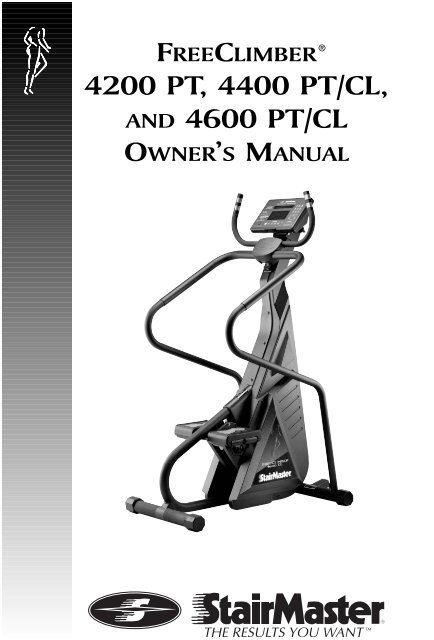
FREECLIMBER<strong>4200</strong> PT, <strong>4400</strong> PT/CL,AND <strong>4600</strong> PT/CLOWNER’S MANUAL®
Printed in the United States.© 2001 StairMaster ® Health & Fitness Products, Inc.All rights reserved.Corporate Headquarters12421 Willows Road N.E., Suite 100Kirkl<strong>and</strong>, WA 98034(800) 635-2936(425) 823-1825Fax (425) 823-9490www.stairmaster.<strong>com</strong>P/N 22867-A© 2001 StairMaster Health & Fitness Products, Inc. StairMaster <strong>and</strong> FreeClimber areregistered trademarks or trademarks of StairMaster Health & Fitness Products, Inc. in the United States<strong>and</strong>/or other countries. All other trademarks are trademarks of their respective <strong>com</strong>panies.StairMaster is a Rutledge Capital CompanyPage iii
WARRANTYThis is to certify that the StairMaster ® FreeClimber ® exercise system is warrantedby StairMaster Health & Fitness Products, Inc. to be free of all defects in materials<strong>and</strong> workmanship. This warranty does not apply to any defect caused by negligence,misuse, accident, alteration, improper maintenance, or an “act of God.” This warrantyis non-transferable from the original owner.If, within three years from the date of purchase, any part of the StairMasterFreeClimber exercise system should fail to operate properly (exce<strong>pt</strong> any accessories or thebattery on the <strong>4600</strong> CL <strong>and</strong> the <strong>4400</strong> CL), contact our Customer Service Department toreport the problem. When calling, please be prepared to provide the customer servicerepresentative with the following information:Page iv• Your name, customer number, shipping address, <strong>and</strong> telephone number• The model <strong>and</strong> serial number of the inoperable machine• The date(s) of purchase for the inoperable machine(s)• Your billing addressThis information will ensure that you are the only one ordering parts under yourwarranty protection. If warranty replacement parts are shipped to you, you may berequired to return the inoperable parts. To facilitate this process, the following policyhas been established:• Please call our Customer Service Department to receive a ReturnMaterial Authorization (RMA) prior to shipment.• StairMaster Health & Fitness Products, Inc. will incur all freightcharges for warranty parts ordered for a machine that is less than 45days old. The parts will be shipped to you via an overnight courier.*• You are responsible for freight charges on warranty parts formachines that are more than 45 days old. You will not be responsiblefor the return shipment of the inoperable parts.• Some inoperable warranty parts must be prom<strong>pt</strong>ly returned to ourCustomer Service Department. We will pay the shipping cost for theinoperable warranty parts. Detailed instructions are in<strong>cl</strong>uded witheach warranty replacement part.StairMaster Health & Fitness Products, Inc. neither makes, assumes, norauthorizes any representative or other person to make or assume for us, any otherwarranty whatsoever, whether expressed or implied, in connection with the sale,service, or shipment of our products. We reserve the right to make changes <strong>and</strong>improvements in our products without incurring any obligation to similarly alter productspreviously purchased. In order to maintain your product warranty <strong>and</strong> to ensure the safe<strong>and</strong> efficient operation of your machine, only authorized replacement parts can be used.This warranty is void if parts other than those provided by StairMaster Health & FitnessProducts, Inc. are used.* Note: Aerosol products cannot be transported via air.
PREFACERegular use of the StairMaster ® FreeClimber ® exercise system is a safe <strong>and</strong>effective way to develop aerobic fitness while conditioning the major mus<strong>cl</strong>esof the lower body. To get the best results, <strong>and</strong> to keep your machine in peakoperating condition, you should carefully read <strong>and</strong> follow the guidelinespresented in this manual.WHAT IS IN THIS MANUAL?The first part of this manual in<strong>cl</strong>udes sections on safety, installation, operatinginstructions, <strong>and</strong> preventive maintenance. The second part contains detailedinformation on problem troubleshooting <strong>and</strong> repair procedures. An Appendix atthe end of the manual provides additional information for the owner.Throughout this manual, console keypad keystrokes are en<strong>cl</strong>osed in [ ].The names of the keys <strong>and</strong> special console operational modes are shown incapital letters. For example, your machine is ready to use when the consoledisplays "SELECT WORKOUT." Press [MANUAL] to start the MANUAL exerciseprogram.WHAT IS THE STAIRMASTER FREECLIMBER EXERCISE SYSTEM?The StairMaster FreeClimber exercise systems are vertical <strong>cl</strong>imbing machineswith an independent step action. The independent step action, <strong>com</strong>bined withthe patented pedal geometry featured on all StairMaster steppers, provides anaerobic workout equivalent to uphill running or <strong>cl</strong>imbing stairs, but without thehigh-impact pounding to the joints <strong>and</strong> mus<strong>cl</strong>es.There are five FreeClimber models: the <strong>4600</strong> PT (Personal Trainer),the <strong>4600</strong> CL (Cordless), the <strong>4400</strong> PT, the <strong>4400</strong> CL, <strong>and</strong> the <strong>4200</strong> PT. AllFreeClimbers feature the Quiet Drive transmission. The <strong>4600</strong> PT <strong>and</strong> the<strong>4600</strong> CL have an adjustable tilting, full-featured Liquid Crystal Display (LCD)console. The <strong>4400</strong> PT <strong>and</strong> the <strong>4400</strong> CL have an upright, rail-less design. The<strong>4600</strong> PT <strong>and</strong> the <strong>4400</strong> PT use an external power supply that is plugged into anAC wall outlet. The <strong>4600</strong> CL <strong>and</strong> the <strong>4400</strong> CL use power generated during aworkout to run the electronics. The <strong>4600</strong> PT <strong>and</strong> <strong>4600</strong> CL have contact heartrate <strong>and</strong> telemetry (Polar ® ) heart rate monitoring. The <strong>4400</strong> PT <strong>and</strong> the <strong>4400</strong> CLfeature telemetry heart rate monitoring. The <strong>4200</strong> PT uses an external powersupply <strong>and</strong> the console has less feedback <strong>and</strong> fewer workout programs thanthe <strong>4600</strong> PT/CL <strong>and</strong> the <strong>4400</strong> PT/CL.Page v
CONTENTSSAFFETY GUIDELINES ........................................................................................ 1INTRODUCTION ................................................................................................... 3INSTALLATION INSTRUCTIONS........................................................................ 6BASIC OPERATING INSTRUCTIONS ................................................................ 9General Guidelines for Safe Operation ........................................................... 9Your First Workout......................................................................................... 10Begin Exercising ................................................................................... 10Rest Periods .......................................................................................... 11Cool Down............................................................................................. 11HEART RATE MONITORING ............................................................................ 13Heart Rate Input ........................................................................................... 13Locked/Non-locked O<strong>pt</strong>ion .......................................................................... 13Error Messages ............................................................................................ 14TELEMETRY HEART RATE (<strong>4400</strong>/<strong>4600</strong> PT/CL ONLY) .................................. 15Using the Transmitter Belt ........................................................................... 15Maintaining the Transmitter Belt ................................................................ 16CONTACT HEART RATE.................................................................................... 17Using Contact Heart Rate ............................................................................ 17FREECLIMBER <strong>4400</strong>/<strong>4600</strong> PT/CL CONSOLE.................................................. 18Display Window ........................................................................................... 18Numeric Keypad ........................................................................................... 19Entertainment Keypad ................................................................................. 19Intensity Level Keys ..................................................................................... 19Stop Key ....................................................................................................... 19Workout Statistics ........................................................................................ 20Exercise Program Keypad ............................................................................ 21The Quick Start Program ...................................................................... 21The Manual Program ........................................................................... 21The Fat Burner Program ....................................................................... 22The Aerobic Training Program ............................................................. 22The Speed Intervals Program .............................................................. 22The Constant Heart Rate Program ...................................................... 23Page vi
CONTENTSThe Fitness Test Programs ................................................................... 24Underst<strong>and</strong>ing Submaximal Exercise Testing .................................... 24Pretest Screening ................................................................................. 26The StairMaster ® Submaximal Fit Test ............................................... 26The Firefighter's Stair Climb Tests....................................................... 29Turning on the C.P.A.T. Test ........................................................... 30Turning on the NYCFD Test ........................................................... 30Console Codes ............................................................................................. 31Custom Codes ...................................................................................... 31Quick Scan Programming .............................................................. 32Machine Status Codes ........................................................................ 33Quick Scan Programming .............................................................. 34Configuration Code .............................................................................. 34FREECLIMBER <strong>4200</strong> PT CONSOLE ................................................................. 35Top Window.................................................................................................. 35Workout Setup...................................................................................... 35Timer ...................................................................................................... 36Bottom Window ........................................................................................... 37Keypad .................................................................................................. 37Quick Start O<strong>pt</strong>ion ........................................................................................ 38MAINTENANCE INSTRUCTIONS .................................................................. 39Helpful Hints ................................................................................................. 39Tool List ......................................................................................................... 39Maintenance Records ................................................................................. 39Initial Service ................................................................................................ 40Preventive Maintenance ............................................................................. 40Cleaning ................................................................................................ 40Inspecting ............................................................................................. 40Lubrication ............................................................................................ 41Battery Charge...................................................................................... 42Battery Disposal ................................................................................... 42TROUBLESHOOTING ........................................................................................ 44General Troubleshooting Guidelines ........................................................... 44Electrical Troubleshooting ........................................................................... 44<strong>4600</strong>/<strong>4400</strong> PT: ...................................................................................... 44Alternator Test ............................................................................... 45Page vii
CONTENTSDiode Test....................................................................................... 46Resistor Test................................................................................... 46<strong>4600</strong>/<strong>4400</strong> CL: ...................................................................................... 46Battery Test .................................................................................... 46Alternator Test ............................................................................... 47Resistor Test................................................................................... 47Display Test ........................................................................................... 48Keypad Test .......................................................................................... 48Serial Port Test...................................................................................... 49Alternator Test ...................................................................................... 49Tach Test ............................................................................................... 50Error Reporting...................................................................................... 50Contact Heart Rate Test ....................................................................... 51Telemetry Heart Rate Test .................................................................... 51Mechanical Troubleshooting ....................................................................... 53PARTS REMOVAL AND REPLACEMENT ....................................................... 56Covers ........................................................................................................... 56Mid Cover ............................................................................................. 56Top Cover .............................................................................................. 56Shield (<strong>4600</strong> PT/CL ) ............................................................................. 57Bottom Cover ........................................................................................ 57Console ......................................................................................................... 58Console Adjustment (<strong>4600</strong> PT/CL) .............................................................. 58Poly-V <strong>and</strong> HTD Belt ..................................................................................... 58Step Chain Retainer ..................................................................................... 59Pedal Arm Return Spring ............................................................................. 59Step Chain .................................................................................................... 60Spring Pulley ................................................................................................. 61Drive Chain ................................................................................................... 61Drive Shaft Assembly ................................................................................... 62Pedal ............................................................................................................. 64Leveling Arm ................................................................................................. 64Pedal Arm...................................................................................................... 65Pedal Pad ...................................................................................................... 65Eccentric Hub Assembly ............................................................................... 66Page viii
First Reduction Shaft Assembly .................................................................. 66H<strong>and</strong>lebar (<strong>4400</strong> PT/CL, <strong>4200</strong> PT) ............................................................... 66Upper H<strong>and</strong>les (<strong>4600</strong> PT/CL) ........................................................................ 67Side H<strong>and</strong>rails (<strong>4600</strong> PT/CL) ........................................................................ 67Alternator ...................................................................................................... 68GROUNDING INSTRUCTIONS ......................................................................... 69FCC COMPLIANCE ............................................................................................. 70APPENDICESCanadian Doc Class B Compliance ............................................................. 70Important Phone Numbers ........................................................................... 71Battery Recy<strong>cl</strong>ing Centers ........................................................................... 72Figures 10-27 ................................................................................................ 74LIST OF TABLESTable 1. Dimensions <strong>and</strong> Specifications for theStairMaster ® FreeClimber ® Exercise Systems .................................. 5Table 2. Fitness Rating Norms (VO 2max) ........................................................ 29Table 3. Re<strong>com</strong>mended Preventive Maintenance Schedule .................... 43LIST OF ILLUSTRATIONSCONTENTSFigure 1: Major Parts - <strong>4600</strong> PT/CL ................................................................. 3Figure 2: Major Parts - <strong>4200</strong> PT <strong>and</strong> <strong>4400</strong> PT/CL ......................................... 4Figure 3: Level Adjusting End Caps ............................................................... 6Figure 4: DC Power Connector....................................................................... 7Figure 5: Correct Exercise Postion ............................................................... 12Figure 6: Transmitter Belt ............................................................................. 16Figure 7: FreeClimber <strong>4400</strong>/<strong>4600</strong> PT/CL Systems Console ....................... 18Figure 8: StairMaster Fitness Protocol ........................................................ 28Figure 9: <strong>4200</strong> PT Console Diagram ............................................................ 35Figure 10: Grounding System ...................................................................... 69Figure 11: Parts Needing Periodic Maintenance ....................................... 74Page ix
CONTENTSFigure 12: Final Assembly - Left, <strong>4600</strong> PT ................................................... 75Figure 13: Final Assembly - Right, <strong>4600</strong> PT ................................................. 76Figure 14: Final Assembly - Left, <strong>4600</strong> CL ................................................... 77Figure 15: Final Assembly - Right, <strong>4600</strong> CL ................................................. 78Figure 16: Covers - <strong>4600</strong> PT/CL ................................................................... 79Figure 17: Pedal Arm Assembly & First Reduction Shaft Assembly(<strong>4600</strong>/<strong>4400</strong> PT/CL, <strong>4200</strong> PT) ........................................................ 80Figure 18: Drive Shaft Assembly & Eccentric Hub Assembly(<strong>4600</strong>/<strong>4400</strong> PT/CL, <strong>4200</strong> PT) ........................................................ 81Figure 19: Final Assembly - Left, <strong>4400</strong>/<strong>4200</strong> PT ......................................... 82Figure 20: Final Assembly - Right, <strong>4400</strong>/<strong>4200</strong> PT....................................... 83Figure 21: Final Assembly - Left, <strong>4400</strong> CL ................................................... 84Figure 22: Final Assembly - Right, <strong>4400</strong> CL ................................................. 85Figure 23: Covers - <strong>4400</strong> PT/CL, <strong>4200</strong> PT ................................................... 86Figure 24: Cover Removal ............................................................................ 87Figure 25: Cover Fasteners .......................................................................... 88Figure 26: Drive Chain Tensioning .............................................................. 89Figure 27: Belt Tension................................................................................ 90Page x
SAFETY GUIDELINESWHEN USING ELECTRICAL EQUIPMENT, ALWAYS FOLLOW THESE BASIC PRECAUTIONS:IMPORTANT SAFETY INSTRUCTIONS!This symbol appearing throughout this manual meansAttention! Be Alert! Your safety is involved.The following definitions apply to the words “Danger” <strong>and</strong> “Warning”found throughout this manual:DANGER - Used to call attention to IMMEDIATE hazards which, if notavoided, will result in immediate, serious personal injury or loss of life.WARNING - Used to call attention to POTENTIAL hazards that couldresult in personal injury or loss of life.READ ALL INSTRUCTIONS BEFORE USING THE MACHINE.!!DANGERWARNINGTo reduce the risk of electrical shock, always unplugthe external power supply from the AC wall outletbefore <strong>cl</strong>eaning, maintaining, or repairing.To reduce the risk of burns, electric shock, or injuryto persons:1. The external power supply should always be unplugged from the AC walloutlet before removing or installing parts. Never make adjustments orrepairs while an exercise program is in progress.2. Close supervision is necessary whenever the machine is used by or nearchildren, invalids, or disabled persons.3. Keep your h<strong>and</strong>s away from all moving parts <strong>and</strong> keep your feet on thepedals while exercising. Do not operate the machine with the side coversremoved.Page 1
SAFETY GUIDELINES4. Use this machine only for its intended use as described in this Manual. Donot use parts, attachments, or accessories other than those provided byStairMaster ® Health & Fitness Products, Inc.5. Do not use the external power supply if it has a damaged cord or plug, or ifit is not working properly, if it has been dropped or damaged, or droppedinto water. Contact our Customer Service Department at 1-800-331-3578 to arrange for the return of damaged parts.6. Connect the external power supply to a properly grounded AC walloutlet; refer to the “Grounding Instructions” section. Keep all cordsaway from heated surfaces.7. To disconnect the external power supply, remove the plug from the ACwall outlet.8. Never drop or insert any object into any opening on the machine.9. Do not operate where aerosol (spray) products are being used.10. Always wear insulated gloves when h<strong>and</strong>ling batteries.11. Do not crush, incinerate, or dismantle the battery. The electrolyte containssulfuric acid which can cause serious damage to eyes <strong>and</strong> skin. Shouldthis occur, flush profusely with water <strong>and</strong> seek medical attention.12. Do not use the machine outdoors.The safety level given by the design of this equipment can only bemaintained when the equipment is regularly examined for damage <strong>and</strong> wear.Inoperable <strong>com</strong>ponents shall be replaced immediately or the equipment shallbe put out of use until it is repaired. Failure to follow all guidelines may <strong>com</strong>promisethe effectiveness of the exercise experience, expose yourself (<strong>and</strong>possibly others) to injury, <strong>and</strong> reduce the longevity of the machine. Follow alltraining instructions listed in the manual <strong>and</strong>/or on the machine. Physical injurymay result from incorrect or excessive training.Page 2SAVE THESE INSTRUCTIONS
INTRODUCTIONBefore leaving the manufacturing facility in Tulsa, Oklahoma, yourStairMaster ® FreeClimber ® exercise system was thoroughly inspected <strong>and</strong>tested to ensure proper operation. The major parts of the machine are shownin Figures 1 <strong>and</strong> 2.Figure 1: Major Parts - <strong>4600</strong> PT/CLPage 3
INTRODUCTIONFigure 2: Major Parts - <strong>4200</strong> PT <strong>and</strong> <strong>4400</strong> PT/CLPage 4
INTRODUCTIONThroughout this Manual, all references to the left or right side <strong>and</strong> to thefront or back are made as if you were on the machine, ready to exercise. Forexample, the console is located on the front of the machine. The dimensions<strong>and</strong> general specifications of the machines are listed in Table 1.Table 1. Dimensions <strong>and</strong> Specifications for theStairMaster ® FreeClimber ® Exercise SystemsPhysical Dimensions:Length44 inches (104 cm)Width at Front Leg (<strong>4400</strong> PT/CL, <strong>4200</strong> PT) 22 inches (56 cm)Width at Front Leg (<strong>4600</strong> PT/CL)32 inches (82 cm)Height69 inches (176 cm)Weight<strong>4400</strong> PT/CL, <strong>4200</strong> PT 126 pounds (55 kg)<strong>4600</strong> PT/CL 155 pounds (70 kg)Power Supply Specifications:<strong>4600</strong>/<strong>4400</strong>/<strong>4200</strong> PT (U.S., Canada, Japan) 120 VAC, 50/60 Hz, 2.5 Amp<strong>4600</strong>/<strong>4400</strong>/<strong>4200</strong> PT (International) 230 VAC, 50/60 Hz, 2.5 AmpBattery Charger Specifications:<strong>4600</strong>/<strong>4400</strong> CL (U.S., Canada, Japan) 120 VAC, 50/60 Hz, 1 Amp<strong>4600</strong>/<strong>4400</strong> CL (International) 230 VAC, 50/60 Hz, 1 AmpInternal Battery6 volt, 1 Ah Lead-Acid batteryPage 5
INSTALLATION INSTRUCTIONSAssemble your machine before use. Machines shipped outside the UnitedStates need to be uncrated before they can be assembled; refer to the“Uncrating Instructions” in<strong>cl</strong>uded with your machine for the details.1. Remove all shipping material from your machine once it is in place.2. Make sure the machine is level before you use it for the first time. Thefour rubber end caps (see Figure 3) are designed to <strong>com</strong>pensate foruneven floors. Each face of the caps is a different thickness. Twist thecaps to stabilize the machine.Figure 3: Level Adjusting End Caps3. Open the box you removed from the pedals. The box contains eitheran external power supply (<strong>4600</strong>/<strong>4400</strong>/<strong>4200</strong> PT only) or a wall-packbattery charger (<strong>4600</strong>/<strong>4400</strong> CL only). The battery charger is onlyused to recharge a low battery.Page 6
INSTALLATION INSTRUCTIONS4. If you have a <strong>4600</strong>/<strong>4400</strong> CL, skip to step 9. If you have a <strong>4600</strong>/<strong>4400</strong>/<strong>4200</strong> PT, connect the DC cable of the power supply to the connectornear the bottom of the left side cover (see Figure 4).Figure 4: DC Power Connector5. Place the power supply on the floor near an AC wall outlet. To reducethe hazard of electrical shock, place the power supply in a locationaway from the machine <strong>and</strong> away from exposure to perspiration. Youshould not place your power supply on a carpet because it may overheat.Page 7
INSTALLATION INSTRUCTIONS6. Check to be sure that the input AC power rating marked on the powersupply matches the available power. If it does not, obtain the matchingpower supply from StairMaster ® Health & Fitness Products, Inc.before proceeding any further.! WARNINGTO REDUCE THE RISK OF ELECTRICAL SHOCK AND FIRE AND TOPREVENT SEVERE DAMAGE TO THE MACHINE, USE ONLY THE POWER SUPPLYAPPROVED FOR USE WITH THIS EQUIPMENT. IN ADDITION,YOUR MACHINE MUST BE PROPERLY GROUNDED.7. Connect the AC power cord to the AC wall outlet. Refer to the“Grounding Instructions” section if the AC wall outlet does notacce<strong>pt</strong> athree-prong plug.8. Watch the console. The <strong>4600</strong>/<strong>4400</strong> PT should display a softwarerevision code <strong>and</strong> then show “SELECT WORKOUT.” The <strong>4200</strong> PTconsole should run through a self test <strong>and</strong> then display a moving linein the upper LCD window. If the console does not, unplug the powersupply <strong>and</strong> then plug it back in. If the console still does not power upcorrectly, contact our Customer Service Department. Refer to theAppendix for the appropriate phone number.9. If you have a <strong>4600</strong>/<strong>4400</strong> CL, step on the pedals to check for properoperation. Once you step on the pedals, the console should display asoftware revision code <strong>and</strong> then show “SELECT WORKOUT.” If itdoes not, connect the battery charger to the connector on the lowerleft side. If the console still does not power up contact our CustomerService Department. Refer to the Appendix for the appropriate phonenumber.10. The display “SELECT WORKOUT” tells you the machine is ready touse. The <strong>4600</strong>/<strong>4400</strong> PT/CL console displays this message <strong>and</strong> the<strong>4200</strong> PT displays a moving line in the upper LCD window when theconsole is ready to use.Page 8
GENERAL GUIDELINES FOR SAFE OPERATIONBASIC OPERATING INSTRUCTIONS! WARNINGTHESE GUIDELINES ARE DIRECTED TO YOU, AS THE OWNER OF THE MACHINE.YOU SHOULD INSIST THAT ALL USERS FOLLOW THE SAME GUIDELINES.YOU SHOULD MAKE THIS MANUAL AVAILABLE TO ALL USERS.1. Obtain a <strong>com</strong>plete physical examination from your medical doctor <strong>and</strong>enlist a health/fitness professional’s aid in developing an exerciseprogram suitable for your current health status.2. When working out for the first time, use the MANUAL exerciseprogram at the lower speeds until you feel <strong>com</strong>fortable <strong>and</strong> capableof faster speeds.3. The speed <strong>and</strong> duration of your exercise program should always besubject to how you feel. Never permit peer pressure to override yourpersonal judgment while exercising.4. Overweight or severely deconditioned individuals should be particularlycautious when using the machine for the first time. Even thoughsuch individuals may not have histories of serious physical problems,they may perceive the exercise to be far less intense than it really is,resulting in the possibility of overexertion or injury.5. Although all equipment manufactured by StairMaster ® Health &Fitness Products, Inc. has been thoroughly inspected by the manufacturingfacility prior to shipment, proper installation <strong>and</strong> regular maintenanceare required to ensure safety. Maintenance is the sole responsibilityof the owner.Page 9
BASIC OPERATING INSTRUCTIONSYOUR FIRST WORKOUT ON THE STAIRMASTER ® FREECLIMBER ®EXERCISE SYSTEM1. Warm up with light calisthenics <strong>and</strong> easy stretching exercises for atleast five minutes before beginning your exercise program.2. Hold onto the h<strong>and</strong>lebars <strong>and</strong> step up onto the pedals. St<strong>and</strong> upstraight. The pedals will sink slowly toward the floor.3. Select the MANUAL exercise program so you can control the pace ofyour first workout <strong>and</strong> get used to the exercise motion. Press[MANUAL] <strong>and</strong> then press [ENTER]. The console will return tothe start screen if you do not press [ENTER] within 60 seconds.4. The console will prom<strong>pt</strong> you to enter your body weight. Enter yourweight in pounds (or kilograms if the console is set up for metricunits). Correct entry errors by pressing [CLEAR] before you press[ENTER].5. The console will prom<strong>pt</strong> you to enter your intensity level. Enter yourdesired intensity level. Correct entry errors by pressing [CLEAR] beforeyou press [ENTER].6. The console will prom<strong>pt</strong> you to enter the workout time in one minuteincrements between 5 <strong>and</strong> 99 minutes. Press [1], [0], [ENTER] toexercise for ten minutes. If you do not start exercising within 60seconds, the console will return to the start screen.Begin Exercising7. Take deep, <strong>com</strong>fortable steps. Do not let the pedals touch the floor orcontact the upper stop. When you begin to exercise, the MANUALPage 10! WARNINGIF AT ANY TIME DURING YOUR WORKOUT YOU FEEL CHEST PAIN,EXPERIENCE SEVERE MUSCULAR DISCOMFORT, FEEL FAINT, OR ARE SHORT OFBREATH, STOP EXERCISING IMMEDIATELY. IF THE CONDITION PERSISTS, YOUSHOULD CONSULT YOUR MEDICAL DOCTOR IMMEDIATELY.
program starts at level three.8. As you be<strong>com</strong>e <strong>com</strong>fortable with exercise motion, press[LEVEL: ∧] <strong>and</strong> [LEVEL: ∨] to adjust your <strong>cl</strong>imbing speed.9. Relax <strong>and</strong> st<strong>and</strong> up straight while exercising. Use theh<strong>and</strong>lebars for balance (see Figure 5).10. Select an intensity level that allows you to stay in the middleof the pedal range of motion. Faster is not always better.Exercise at a level that is consistent with your fitness level.Rest Periods11. You can stop <strong>and</strong> rest as many times as necessary for up to oneminute for each rest period during all programs. To stop, either press[STOP] or step off the machine.The <strong>4400</strong>/<strong>4600</strong> PT console returns tothe start screen if you rest longer than the allotted rest period. The<strong>4400</strong>/<strong>4600</strong> CL console will shut off if you rest longer than the allottedrest period. Follow the onscreen prom<strong>pt</strong> to continue your work outafter a rest period.Cool DownBASIC OPERATING INSTRUCTIONS12. When you are finished with your workout, the machine will slowdown <strong>and</strong> the message “GOAL ATTAINED” will be displayed. You cancool down on the machine by continuing to step. The console timerwill continue to count up from the selected time, <strong>and</strong> the intensitylevel will default to level 3. If there is a time limit set on the console,the timer will last only until the maximum time has been met. Forexample, if the time limit was set for 30 minutes <strong>and</strong> you worked outfor 25 minutes, the cool down period would last for 5 minutes, or untilyou stepped off the machine.13. You can also cool down by getting off the machine walking orstretching for at least five minutes. Lift one foot slowly until the pedalarm contacts the upper stop. Place that foot on the floor. Repeat forthe other foot. Do not let the pedals slam into the upper stops, sincethis may cause unnecessary wear <strong>and</strong> tear.Page 11
BASIC OPERATING INSTRUCTIONSFigure 5: Correct Exercise PositionHead - Keep your chin parallelto the floor. Avoid staring at yourfeet or the <strong>com</strong>puter console. Thisposture will also enhance yourbreathing.Back - Although the wholebody is in a slightly forwardslant, keep your back straight<strong>and</strong> avoid bending at the waist.Hips/Torso - Keep your hipsdirectly under you with thebuttocks slightly contracted.Avoid letting your hips rockfrom side to side with each step.Legs - Use a full, pain-freerange of motion with eachstep, straightening your legsas far as possible withoutcausing dis<strong>com</strong>fort or lettingyour knees lock out.Chest/Shoulders - Keep yourshoulders square <strong>and</strong> centeredover your hips with your chestlifted.H<strong>and</strong>s - Rest yourh<strong>and</strong>s lightly on theside rails or fronth<strong>and</strong>lebars.Excessive leaning onthe side rails can reducecalorie burn byup to 20%.Elbows - Keep both elbowsslightly bent. If you have goodbalance <strong>and</strong> want to burn morecalories, you can pump your armsback <strong>and</strong> forth as if you wererunning.Knees - Keep your kneesaligned with your toes.Avoid training with yourknees too far past yourtoes <strong>and</strong> keep your feetpointing forward. Do nothyperextend your knees.Feet - Place 3/4 of each foot on the pedals,heels slightly off the edge with yourtoes facing forward.Page 12
HEART RATE MONITORINGHEART RATE INPUTContact heart rate <strong>and</strong> telemetry (e.g., Polar ® ) heart rate signal detection isavailable. There is no default priority of heart rate input. If a telemetry signalis detected first, contact heart rate signals are inhibited from being detectedthroughout the rest of the workout session <strong>and</strong> vice-versa. There is also ashort “lock out” period at the beginning of each workout session during whichthe console first detects a signal <strong>and</strong> then validates the signal type. Theduration of this shorter, initial “lock out” period differs between telemetry <strong>and</strong>contact heart rate.• Telemetry heart rate - after the initial belt signal is detected, theconsole will enter a validation phase in which four good heartbeat signals within four seconds are required beforelocking on telemetry heart rate signals for the duration of theworkout session. During the validation phase the console will notrecognize contact heart rate signals.• Contact heart rate - after the initial contact sensor signal isdetected, the console will enter a validation phase requiring agood heart beat signal within 10 to 15 seconds, or until thesystem acquires a valid signal. During the validation phase, theconsole will not recognize telemetry heart rate signals. Theconsole will display a beating double heart icon that has theinner heart colored in while searching for a valid signal.Locked/Non-locked O<strong>pt</strong>ionWhen the “not locked” o<strong>pt</strong>ion is selected the heart rate source signal is notfixed during the exercise (if the signal is lost, either input will be valid). If the“locked” o<strong>pt</strong>ion is selected, then the heart rate source signal is locked on thefirst detected signal during the workout. To set a heart rate signal input, or toturn off the heart rate o<strong>pt</strong>ion all together, perform the following steps:1. On the console keypad, press [LEVEL: ∧], [3], [2]. At this point thescreen will display “HR INPUTS.” Press [ENTER] to select thiso<strong>pt</strong>ion.Page 13
HEART RATE MONITORING2. There are four o<strong>pt</strong>ions to h<strong>and</strong>le heart rate input signals.Press the [SELECT] key to scroll through the o<strong>pt</strong>ions until youfind the one o<strong>pt</strong>ion that suits your needs. Press the [ENTER]key to select that o<strong>pt</strong>ion.Error Messages“ BOTH HR ON “ - allows either telemetry or contact heart ratesignals to be detected. Once the console has detected a validinput signal it will lock out the opposite type of signal for theduration of the workout session. For example, if you start outusing contact heart rate then you are limited to using only contactheart rate during your workout session, even if the signal is lostwhile performing the workout, <strong>and</strong> vice-versa.“ BOTH NOT LOCKED” - allows either telemetry or contactheart rate signals to be detected. Does not lock out a particularinput signal for the entire workout. This o<strong>pt</strong>ion will detect eitherinput signal during a workout session, but only one at a time, <strong>and</strong>only until the other signal terminates.“ TELEMETRY ONLY “ - locks out contact heart rate signals<strong>and</strong> will only detect telemetry signals.“ HAND ONLY “ - locks out telemetry signals <strong>and</strong> will only detectcontact heart rate signals.“ BOTH HR OFF “ - turns off the ability to detect any signal at all.Used in rare situations where there is excessive interference withthe heart rate signals. *This o<strong>pt</strong>ion disables the Constant HRprogram <strong>and</strong> the Fitness Test program.Text line messages are only seen in the Constant Heart Rate <strong>and</strong> Fitness Testprograms due to the design of the program that necessitates a valid heart ratesignal during the program. For these programs, ensure that neither the “BOTHHR OFF” or the “HAND ONLY” o<strong>pt</strong>ion is set as a default o<strong>pt</strong>ion.“CHECK HR BELT” - The heart rate signal has been missing for the last 30seconds in telemetry signal detection.“HR BELT NEEDED” - No telemetry belt signal has been sensed during theinitial setup time.Page 14
“HOLD HR SENSORS” - In contact heart rate signal situations this messagewill <strong>com</strong>e every 30 seconds to prom<strong>pt</strong> the user to hold the sensors.“HR MODE DISABLED” - No heart rate signal is allowed due to the set upo<strong>pt</strong>ion that was chosen. Heart rate monitoring is not possible.TELEMETRY HEART RATE (<strong>4600</strong>/<strong>4400</strong> PT/CL ONLY)The StairMaster ® FreeClimber ® <strong>4600</strong>/<strong>4400</strong> PT/CL features telemetry (Polar ® )heart rate monitoring. The system consists of the receiver, located on the stepper,<strong>and</strong> a transmitter belt (purchased separately) worn across your chest. Themonitoring function is activated as soon as you strap on the chest belt <strong>and</strong>step within range of the receiver in the machine. Two electrodes on the undersideof the chest belt sense the heart rate signal <strong>and</strong> send it to the receiver.The heart symbol on the console pulses to indicate that the console is receivinga valid signal. A microprocessor in the console calculates the heart rate<strong>and</strong> displays it, in beats per minute, on the console.Using the Transmitter BeltTELEMETRY HEART RATE! WARNINGPACEMAKER USERS SHOULD NOT USE THE POLARTRANMITTER BEFORE CONSULTING THEIR DOCTOR.Before you put the transmitter belt on, wet the two electrode patches(the grooved rectangles on the reverse side of the belt). Secure the transmitterbelt as high under the pectoral mus<strong>cl</strong>es (chest) as is <strong>com</strong>fortable. The transmitterbelt should fit snugly <strong>and</strong> <strong>com</strong>fortably, <strong>and</strong> allow normal breathing. Whenthe console detects a heart rate signal, heart rate is shown in the display automatically.Your heart rate in beats per minute <strong>and</strong> a pulsing heart icon are displayedon the console.After the initial belt signal is detected, the console will enter a validationphase in which four good heart beat signals lasting four seconds arerequired before locking on telemetry heart rate signals for the duration of theworkout session. During the validation phase the console will not recognizePage 15
TELEMETRY HEART RATEcontact heart rate signals. If you do not see a heart rate on the console, try oneof the following:• Move <strong>cl</strong>oser to the console.• Tighten the elastic part of the chest belt.• Adjust the belt higher or lower on your chest.• Remoisten the electrodes.• Test your chest strap with a machine that you know is working, orwith a heart rate watch that you know is working.• If possible, replace or exchange your console with a console(from the same type of machine) that you know is working <strong>and</strong>retest the machine.• Verify that the console software has been set up properly forheart rate detection (see pg. 13-14).Figure 6: Transmitter BeltMaintaining the Transmitter BeltClean the chest belt regularly with mild soap <strong>and</strong> water, then dry thoroughly -residual sweat <strong>and</strong> moisture keep the transmitter active <strong>and</strong> drain the batteryin the transmitter. Do not use abrasives or chemicals such as steel wool oralcohol for <strong>cl</strong>eaning, as they can damage the electrodes permanently. You canorder replacement belts from StairMaster, Polar Electro, Inc., or your localfitness store:StairMaster 800-331-3578 P/N 64000Polar Electro, Inc. 800-227-1314Page 16
CONTACT HEART RATECONTACT HEART RATEThe StairMaster ® FreeClimber ® <strong>4600</strong> PT/CL features a digitized contact heartrate monitoring system. Through the use of stainless steel sensors built intothe upper h<strong>and</strong>les <strong>and</strong> sophisticated software, heart rate can be checked atany time during a workout. The heart rate is displayed on the console. Contactheart monitoring is st<strong>and</strong>ard on the <strong>4600</strong> PT/CL <strong>and</strong> o<strong>pt</strong>ional on the <strong>4400</strong>PT/CL.The contact heart rate system is very accurate (within 3% of themedical st<strong>and</strong>ard), but its ability to detect a heart rate signal is influenced byseveral factors. Movement of the mus<strong>cl</strong>es of the upper body produces anelectrical signal (mus<strong>cl</strong>e artifact) that will interfere with the detection of theheart rate signal by the sensors. Movement of the h<strong>and</strong>s while they are incontact with the sensors also produces interference. Calluses <strong>and</strong> h<strong>and</strong> lotionact as an insulating layer to reduce the signal strength. Also, the EKG signalgenerated by some individuals is not strong enough to be detected by thesensors. Typically, these individuals account for 5 - 7% of the population.These individuals should o<strong>pt</strong> for the Polar ® chest strap method of heart ratemonitoring. Most people (between 93 – 95%) will not have a problem with thesystem provided interference from movement is minimal.Using Contact Heart RateContact heart rate input signals are acquired only during contactbetween your h<strong>and</strong>s <strong>and</strong> the stainless steel sensors on the h<strong>and</strong>rails. To usethe contact heart rate feature, place your h<strong>and</strong>s around the h<strong>and</strong>les so thatyour h<strong>and</strong>s touch both the top <strong>and</strong> the bottom of the sensors. After the initialcontact heart rate signal is detected, the console will enter a validation phaserequiring a good heart beat signal within 10 to 15 seconds, or until the systemacquires a valid signal. During the validation phase the console will not recognizetelemetry heart rate signals. The console will display a beating doubleheart icon that has the inner heart colored in while searching for a valid signal.If, during exercise, the heart rate displayed is erratic, it may be helpful toremove your h<strong>and</strong>s from the h<strong>and</strong>les, wipe them <strong>and</strong> place them back on theh<strong>and</strong>les. In all programs, the heart rate is shown automatically in the displaywindow the first time the sensors are touched.Page 17
FREECLIMBER <strong>4400</strong>/<strong>4600</strong> PT/CL CONSOLEThe StairMaster ® FreeClimber <strong>4400</strong>/<strong>4600</strong> PT/CL systems console is dividedinto seven sections: the display window, the workout o<strong>pt</strong>ions, the numeric keypad,the entertainment keypad, the workout statistics, the stop key, <strong>and</strong> theintensity level keys (see Figure 7).Display WindowEntertainmentKeypadWorkout O<strong>pt</strong>ionsNumericKeypadPage 18Figure 7: FreeClimber <strong>4400</strong>/<strong>4600</strong> PT/CL Systems ConsoleDISPLAY WINDOWWorkout Statistics Stop Intensity Level• Time - The selected workout time is displayed inthe upper left section of the display window. Oncethe time is entered, the timer will count down, in minutes<strong>and</strong> seconds, until the workout is finished orstopped. If [0] is entered in the MANUAL or CON-STANT HEART RATE program, the timer will count up.• Calories - The real-time amount of calories burned is continually updated<strong>and</strong> displayed in the upper right section of the display window.• Interval Timer - The interval timer is displayed below the Time. The intervaltimer counts down time left within each interval.• Heart Rate - Current heart rate is displayed below the Calories, next to theheart icon.• Workout O<strong>pt</strong>ion Profile - A profile of the selected exercise program appearsin the lower section of the display window during a workout. The tallerthe column, the higher the intensity (watts) for that interval. The flashing columnshows your current interval. The flashing column moves from left to rightacross the display as you <strong>com</strong>plete each interval.
FREECLIMBER <strong>4400</strong>/<strong>4600</strong> PT/CL CONSOLENUMERIC KEYPADThe numeric keypad is located on the right side of the console.Before the exercise program begins, the numbers areused to enter data in response to the console prom<strong>pt</strong>s.• Enter - Confirms workout selections <strong>and</strong> stores the informationused by the console to calculate workout statistics.• Clear - Erases information from the console memory ifpressed before [ENTER].ENTERTAINMENT KEYPADThe FreeClimber <strong>com</strong>es equipped to facilitate the use of <strong>com</strong>mercialentertainment systems. Using any of these keys willsend an output signal through the Communication Specificationfor Fitness Equipment (C.S.A.F.E.) port to a connectedC.S.A.F.E. or <strong>com</strong>patible system. If a system is not connected,pressing these keys will have no effect.• Volume Up/Down - Increases or decreases the volume level of the audiosource.• Mute - Removes the audio sound from the headphones.• Channel Up/Down - Changes the channel of the <strong>com</strong>mercial entertainmentsystem.INTENSITY LEVEL KEYSThe exercise intensity level may be changed at any time duringa workout. Pressing the [ ∨ ] key decreases the intensity<strong>and</strong> pressing the [ ∧ ] key increases the intensity.STOP KEYPress the [STOP] key any time you want to pause the exerciseprogram for up to one minute. Press [STOP] a second time, or[1], <strong>and</strong> The console will return to the "SELECT WORKOUT"Prom<strong>pt</strong>.Page 19
FREECLIMBER <strong>4400</strong>/<strong>4600</strong> PT/CL CONSOLEWORKOUT STATISTICSDuring the exercise program, the Stats keys are used to track workout statisticswhich are then shown in the display window. Pressing the [SELECT] keyturns off the scanning feature <strong>and</strong> shows the statistic of choice in the displaywindow. Continue to press the [SELECT] key until you reach the desiredstatistic. Pressing the [SCAN] key will prom<strong>pt</strong> the console to cy<strong>cl</strong>e through thefollowing statistics:• Distance - Provides a cumulative total of the equivalent distance (in milesor kilometers), you would have traveled while riding a bicy<strong>cl</strong>e outdoors at thesame relative intensity.• Calories/Hour - Provides a running total of the number of calories burnedduring a workout.• Rate - Displays the current steps per minute.• Floors - Displays the equivalent number of floors <strong>cl</strong>imbed with an 8-inchstep. There are 16 steps per floor, <strong>and</strong> 48 floors per mile.• Level - Shows the current intensity level between 1 (the easiest) <strong>and</strong> 20 (thehardest).• Watts - Displays the exercise intensity in watts (746 watts = 1 horsepower).• METs - Gives you the relative energy cost of exercise. MET st<strong>and</strong>s for multiplesof the resting metabolic rate. While you are sitting quietly, your bodyconsumes oxygen at the rate of about 3.5 milliliters per kilogram of body massper minute. When you exercise, your body needs more oxygen in order to function.For example, exercising at 10 METs requires ten times the resting rate ofoxygen consum<strong>pt</strong>ion, or about 35 milliliters per kilogram per minute. During aworkout, this key shows the current MET level. During the workout summary,the average MET level is displayed.• Target Heart Rate - Available only during the Constant Heart Rate program.Shows the selected target heart rate.At the <strong>com</strong>pletion of a workout, the statistic averages are calculatedbased on the accumulation of data during the workout program, <strong>and</strong> not notin<strong>cl</strong>uding the cool down period.Page 20
EXERCISE PROGRAM KEYPADThe exercise keypad is located below the display <strong>and</strong> to the left of the functionkeypad. While the console is in the “SELECT WORKOUT” mode, press one ofthe exercise program keys to preview the desired workout. There are sixworkout programs with the following st<strong>and</strong>ard defaults (pressing [ENTER]without inputting data first will prom<strong>pt</strong> the console to enter these values):• Weight - 175 lbs.• Intensity Level - 3• Workout Time - The default time in the programmed workouts<strong>and</strong> Quick Start is 20 minutes. The Manual <strong>and</strong> Constant HeartRate programs do not have a specified default time. In theseprograms, the console timer will count up to the maximum time of99 minutes, <strong>and</strong> then return to 0.• Age (Constant Heart Rate program only) - 40 yearsOnce you have selected a program, the prom<strong>pt</strong>s are:• “ENTER BODY WEIGHT” - type in your body weight inpounds (or kilograms if your console is set to metric units).• “ENTER LEVEL 1 - 20” - select your intensity level withlevel 1 being the easiest <strong>and</strong> level 20 the hardest.• “ENTER TIME 5 - 99” - select the workout duration in oneminute increments from 5 to 99. Press 0 in the MANUAL <strong>and</strong>CONSTANT HEART RATE program to workout for an unspecifiedamount of time.The Quick Start ProgramProvides an immediate start, without having to enter any user information. Thisprogram uses the st<strong>and</strong>ard default settings for derivation of calories burned.The Manual ProgramFREECLIMBER <strong>4400</strong>/<strong>4600</strong> PT/CL CONSOLEAfter pressing the [MANUAL] key, enter user <strong>and</strong> workout information. Beginexercising at the selected level. If desired, adjust the workout manually byusing the intensity level arrow keys. The profile in the display window isdivided into 15 equal intervals within the workout time. The profile is basedPage 21
FREECLIMBER <strong>4400</strong>/<strong>4600</strong> PT/CL CONSOLEon the selected intensity level, with 2 levels equating to one vertical bar.The Fat Burner ProgramThe Fat Burner program is a 60-interval workout designed for people juststarting a weight control program. The relative intensity level is indicated onthe profile <strong>and</strong> any changes in the intensity level will continue for theremainder of the program.The Aerobic Training ProgramThe Aerobic Training program is a 60-interval workout designed to increaseaerobic capacity. The relative intensity level is indicated on the profile <strong>and</strong> anychanges in the intensity level will not change the look of the remaining profile.The Speed Intervals ProgramThe Speed Intervals program is a workout with 8-rest intervals <strong>and</strong> 7-exerciseintervals that alternate speed/intensity level changes. You can change theREST interval speed/level <strong>and</strong> the EXERCISE interval speed/level independently,using the level keys. For example, if you decrease the intensity levelduring a rest interval then subsequent rest intervals will be the same. However,the EXERCISE interval remains at the same intensity level you startedwith. To change the intensity level of the EXERCISE interval, you must changePage 22
FREECLIMBER <strong>4400</strong>/<strong>4600</strong> PT/CL CONSOLEthe intensity level during an EXERCISE interval. The intensity level shown duringan EXERCISE interval is indicative of your current speed. However, the currentspeed during a REST interval is equal to a scaled percentage of the displayedintensity level. Note that the program profile does not change at anytime during the workout session.Rest IntervalExercise IntervalThe Constant Heart Rate ProgramThe Constant Heart Rate program maintains a chosen target heart rate byautomatically varying the <strong>cl</strong>imbing speed during each workout. The defaulttarget heart rate is equal to 70% of your maximum heart rate which is calculatedby the following equation: 220 - (Age) x .70. Choose a different targetheart rate (between 80 <strong>and</strong> 180 beats per minute) at any time during the workoutby using the numeric keypad to enter the new target heart rate, followedby the [ENTER] key. The following messages may be shown during a workout:• “CHECK HR BELT” - The heart rate signal has been missing forthe last 30 seconds in telemetry signal detection.• “HR BELT NEEDED” - No telemetry belt signal has been sensedduring the initial setup time.• “HOLD HR SENSORS” - In contact heart rate signal situationsthis message will <strong>com</strong>e every 30 seconds to prom<strong>pt</strong> the user tohold the sensors.• “HR MODE DISABLED” - No heart rate signal is allowed due tothe set up o<strong>pt</strong>ion that was chosen. Heart rate monitoring is notpossible.Page 23
FREECLIMBER <strong>4400</strong>/<strong>4600</strong> PT/CL CONSOLETHE FITNESS TEST PROGRAMSUnderst<strong>and</strong>ing Submaximal Exercise TestingBefore using the StairMaster ® FreeClimber ® for submaximal exercise testing,it should be noted that all submaximal fitness tests make several assum<strong>pt</strong>ions:Page 24• That a steady-state heart rate is obtained for each exerciseworkload.• That a linear relationship exists between heart rate, oxygenu<strong>pt</strong>ake <strong>and</strong> workload.• That the maximal heart rate for a given age is uniform.• That the mechanical efficiency of the physical activity performed(i.e., oxygen u<strong>pt</strong>ake at a given workload) is the same foreveryone.It should be ke<strong>pt</strong> in mind that any one or all of the above mentionedassum<strong>pt</strong>ions may not be met during a submaximal exercise test. If for anyreason one of the assum<strong>pt</strong>ions is not met, then errors in predicting VO 2 maxwilloccur.Unfortunately, it is often quite difficult to meet all of the requirementsfor the four listed assum<strong>pt</strong>ions. For example, exercising at a given workload foronly a few minutes can involve an insufficient amount of time for many individualsto achieve a true steady-state. To ensure that a steady-state has beenachieved, the heart rate should be measured after two minutes of exercise ata given workload <strong>and</strong> again after the third minute of exercise at that workload.These two heart rates should then be <strong>com</strong>pared. If a difference of more thanfive beats per minute between the two is found, the subject should continue toexercise at one-minute intervals at the same workload until two successiveheart rates differ by less than five beats per minute.It is also important that the submaximal heart rates obtained bebetween 115 <strong>and</strong> 150 beats per minute, because it is within this heart raterange that a linear relationship tends to exist between heart rate <strong>and</strong> oxygenu<strong>pt</strong>ake or workload for most adults. When the heart rate is less than 115,many external factors (e.g., talking, laughing, apprehension, etc.) can greatlyinfluence heart rate. Once the heart rate reaches a level between 115 <strong>and</strong>
FREECLIMBER <strong>4400</strong>/<strong>4600</strong> PT/CL CONSOLE150, external factors no longer influence heart rate, <strong>and</strong> a linear relationshipexists. As the heart rate rises above 150, the heart-rate/oxygen u<strong>pt</strong>ake relationshipbe<strong>com</strong>es curvilinear.The third assum<strong>pt</strong>ion involves maximal heart rate. Maximal heart rateis the greatest heart rate that can be measured when an individual is exercisingto the point of volitional fatigue (i.e., exhaustion) during a graded exercisetest. Several equations have been developed to estimate the average maximalheart rate for humans:• Maximal heart rate = 220 minus age (low estimate)• Maximal heart rate = 210 minus [0.5 x age] (high estimate)• Maximal heart rate = 226 minus age (estimate for olderindividuals)Maximal heart rate can, however, vary greatly among differentindividuals of the same age. One st<strong>and</strong>ard deviation is ±12 bpm, which meansthat two-thirds of the population varies an average of plus or minus 12 heartbeats from the average given by a prediction equation. If an individual’s agepredictedmaximal heart rate is higher than that person’s true maximal heartrate, then his/her estimated VO 2 maxwill be an overestimation of the correct oractual value.The final assum<strong>pt</strong>ion addresses the issue of mechanical efficiency.Oxygen u<strong>pt</strong>ake at any given work rate can vary by approximately 15%between different individuals. Therefore, individuals vary in the amount ofoxygen they require to perform a certain exercise workload. Some individualsare more efficient at performing a given task than others. As a result, the averageoxygen consum<strong>pt</strong>ion associated with a given workload may vary significantlyfrom one person to another. Thus, VO 2 maxpredicted by submaximal exercisetests tends to be overestimated for those who are mechanically efficient<strong>and</strong> underestimated for those who are inefficient.The point to remember is that submaximal exercise testing, thoughnot as precise as maximal exercise testing, is not without advantages. Forexample, the results of such testing can provide a fairly accurate reflection ofan individual’s fitness status without the cost, risk, effort (on the part of thesubject) <strong>and</strong> time involved in max testing. If an individual is given repeatedPage 25
FREECLIMBER <strong>4400</strong>/<strong>4600</strong> PT/CL CONSOLEsubmaximal exercise tests <strong>and</strong> that person’s heart rate response to a fixedworkload is found to decrease over time, it is reasonably safe to con<strong>cl</strong>ude thatthe individual has made improvements in aerobic (cardiorespiratory) fitness,irrespective of the accuracy of the VO 2 maxprediction.Pretest ScreeningPrior to any exercise test (maximal or submaximal), participants should<strong>com</strong>plete a brief health/medical questionnaire, have their resting bloodpressure <strong>and</strong> heart rate measured, <strong>and</strong> provide an informed consent form.The Physical Activity Readiness Questionnaire (PAR-Q) is an example of a validhealth/medical questionnaire for screening individuals prior to submaximalexercise testing. Canadian health <strong>and</strong> fitness practitioners have extensively(<strong>and</strong> quite successfully) used the PAR-Q to determine whether individualsshould be given an exercise test. A “yes” answer to any of the following sevenquestions taken from the PAR-Q would disqualify a participant from taking partin an exercise test until appropriate medical <strong>cl</strong>earance was obtained.Page 26PHYSICAL ACTIVITY READINESS QUESTIONNAIRE (PAR-Q)1. Has your doctor ever said you have a heart condition <strong>and</strong> re<strong>com</strong>mendedonly medically supervised physical activity?2. Do you have chest pain brought on by physical activity?3. Have you developed chest pain within the past month?4. Do you tend to lose consciousness or fall over as a result of dizziness?5. Do you have a bone or joint problem that could be aggravated by theproposed physical activity?6. Has a doctor ever re<strong>com</strong>mended medication for your blood pressureor a heart condition?7. Are you aware, through your own experience or a doctor’s advice, ofany other physical reason against your exercising without medicalsupervision?The StairMaster Submaximal Fit TestThe StairMaster branching protocol is a series of 3-minute stages ofcontinuous exercise at increasing intensity. The first stage is a warmup atapproximately 4 METs. The intensity of the remaining stages is based on theheart rate response to the warmup. The test is designed to raise the steady-
FREECLIMBER <strong>4400</strong>/<strong>4600</strong> PT/CL CONSOLEstate heart rate of the subject to 110 to 150 beats/min for two consecutivestages. It is important to remember that two consecutive heart rate measurementsmust be obtained in the 110 to 150 beats/min range to predict VO 2max.The test typically lasts from 9 to 15 minutes.In the StairMaster protocol, each work rate is performed for 3minutes, with heart rates recorded during the final 4 seconds of the 2 nd <strong>and</strong> 3 rdminutes of each stage. If the heart rates are within 5 beats/min, then theheart rate during the last minute is plotted against the work rate, <strong>and</strong> the programadvances to the next 3-minute stage. The program continues for 2 to 4stages until 2 steady state heart rates between 110 to 150 beats/min are obtainedin 2 consecutive stages. The line generated from the plotted points isthen extended to the age-predicted maximal heart rate. A corresponding maximalwork rate <strong>and</strong> VO 2maxcan then be calculated.At the end of the 3 rd minute of each stage, if the heart rates at the endof the 2 nd <strong>and</strong> 3 rd minute are not within 5 beats/min of each other, then thatwork rate is maintained for an additional minute. At the end of the 4 th minute,the heart rate is <strong>com</strong>pared to the heart rate at the end of the 3 rd minute. If theheart rates are within 5 beats/min, then the heart rate during the 4 th minute isplotted against the work rate. If the heart rate at the end of the 3 rd <strong>and</strong> 4 thminute are not within 5 beats/min, then the work rate is maintained for onemore additional minute. If the heart rate at the end of the 4 th <strong>and</strong> 5 th minutesare within 5 beats/min, then the heart rate at the end of the 5 th minute is plottedagainst the work rate. If the heart rate at the end of the 4 th <strong>and</strong> 5 th minutesare not within 5 beats/min, then the test failed.Once 2 consecutive heart rate measurements are obtained in the 110to 150 beats/min range, then the test ends successfully <strong>and</strong> the results aredisplayed. The estimated maximum aerobic capacity is shown in ml/kg/min<strong>and</strong> METs. Next, the results are <strong>com</strong>pared to normative values for others ofthe same age range <strong>and</strong> gender (see Table 2). Results are stored in the consoleuntil the next person starts an exercise program.Page 27
FREECLIMBER <strong>4400</strong>/<strong>4600</strong> PT/CL CONSOLEFigure 8: StairMaster ® Fitness ProtocolFIT TEST PROTOCOLStairMaster CV ProductsFirst Work Level4 METsIf HR < 100 If 100 115YThird Work Level9 METsThird Work Level8 METsIf HRs >115YIf HRs >115YFourth Work Level11 METsFourth Work Level10 METsTest Complete- Display Results -Test fails if 2 stages ofat least 115 bpm are notobtainedPage 28
Table 2. Fitness Rating Norms (VO 2max)MENAge High Good Average Fair Low20 – 29 >51 51 – 47 47 – 43 42 – 40 50 50 – 45 45 – 41 41 – 37 48 48 – 42 42 – 38 38 – 35 45 45 – 39 38 – 35 35 – 32 43 42 – 35 35 – 32 32 – 29 44 44 – 38 38 – 35 35 – 32 41 41 – 37 37 – 34 34 – 31 40 39 – 34 34 – 31 31 – 28 35 35 – 31 31 – 28 28 – 26 35 35 – 39 29 – 26 26 – 24
FREECLIMBER <strong>4600</strong>/<strong>4400</strong> PT/CL CONSOLEintervals at an intensity of 68 steps/min. The CPAT Stair ClimbTest has a total of 10 intervals <strong>and</strong> lasts for 3 minutes, 20seconds (in<strong>cl</strong>uding warmup).Turning on the CPAT Stair Climb Test1. Press [∧], [9], [1], [ENTER], on the console keypad. Make sure topress in the middle of each key <strong>and</strong> be aware that the correspondingnumbers will not show in the console display.2. The console will prom<strong>pt</strong> you to “BEGIN FIT TEST.” The testcan be stopped at any time by pressing [STOP].• NYCFD Stair Climb Test – (Fit Test #3) The first phase is a warmupinterval at an intensity of 56 steps/min <strong>and</strong> lasts 60 seconds,followed by a 60 second rest period (no stepping). At the endof the rest period the time counter will reset to zero. The secondphase is at an intensity of 68 steps/min <strong>and</strong> lasts for 5 minutes,12 seconds.Turning on the NYCFD Stair Climb Test1. Press [∧], [9], [2], [ENTER], on the console keypad. Make sure topress in the middle of each key <strong>and</strong> be aware that the correspondingnumbers will not show in the console display.2. The console will prom<strong>pt</strong> you to “BEGIN FIT TEST.” The testcan be stopped at any time by pressing [STOP].Page 30
FREECLIMBER <strong>4600</strong>/<strong>4400</strong> PT/CL CONSOLECONSOLE CODESThere are three groups of console codes which are differentiated according tofunction. The first group of codes are customization codes <strong>and</strong> are used to setdefaults such as units, language, heart rate input type, etc. The second groupof codes are machine status codes <strong>and</strong> are used to track hours <strong>and</strong> other generalusage patterns for maintenance purposes. The third group of codes arediagnostic codes <strong>and</strong> are used for troubleshooting. The following key actionsare valid in each group of console codes:• Pressing [LEVEL ∧], [ 1 st # ], [ENTER] displays what group of codes isbeing accessed.• Pressing [SELECT] or [LEVEL ∧] at that point allows you to view allpossible selections. Once in this mode pressing [LEVEL ∨] backs u<strong>pt</strong>hrough the selections; pressing [ENTER] then selects that item. Ifanother test level is available at this point, the [SELECT] / [ENTER]process is repeated.• Pressing [∧] [1 st #, or 2 nd #], [ENTER ] selects that item directly.• Pressing [CLEAR] exits any of the special access modes.Custom Codes[ ^ ] [ 3 ] [ 0 ] change workout time limit between 5 to 99 minutes[ ^ ] [ 3] [ 1 ] change units (MPH or KMH)[ ^ ] [ 3 ] [ 2 ] choose type of heart rate input <strong>and</strong> priority (telemetryor contact)[ ^ ] [ 3 ] [ 3 ] - N/A -[ ^ ] [ 3 ] [ 4 ] choose console language[ ^ ] [ 3 ] [ 5 ] change contrast on console[ ^ ] [ 3 ] [ 6 ] - N/A -[ ^ ] [ 3 ] [ 7 ] - N/A -[ ^ ] [ 3 ] [ 8 ] - N/A -[ ^ ] [ 3 ] [ 9 ] reset to factory defaults1. Change the workout time by pressing [LEVEL: ^], [3 , [0]. The console willdisplay “MAX TIME.” Press [ENTER]. The console will then display thecurrent time limit. Use the keypad to enter the desired time, then press[ENTER]. For no time limit, press [0].Page 31
FREECLIMBER <strong>4600</strong>/<strong>4400</strong> PT/CL CONSOLE2. Change the units to either Metric or USA units by pressing [LEVEL: ^], [3],[1], [ENTER]. The console will display the current units - either “USAUNITS” or “METRIC UNITS.” Use the [SELECT] key to change o<strong>pt</strong>ion, <strong>and</strong>then press [ENTER].3. Choose the desired heart rate input preference by pressing [LEVEL: ^],[3], [2]. The console will then display “HR INPUTS.” Press [ENTER]. Theconsole will then display the current hear rate input selection. Press the[SELECT] key to scroll through the other o<strong>pt</strong>ions. Press [ENTER] after thedesired o<strong>pt</strong>ion.4. Change the language by pressing [LEVEL: ^], [3], [4]. The console willdisplay “LANGUAGE.” Press [ENTER]. The console will then displaythe current language. Press the [SELECT] key to scroll through the othero<strong>pt</strong>ions. Press [ENTER] to change the o<strong>pt</strong>ion.5. Adjust the contrast on the LCD screen by pressing [LEVEL: ^], [3], [5]. Theconsole will display “CONTRAST ADJ.” Press [ENTER]. The console willthen display the current contrast number. Press the [LEVEL: ^], <strong>and</strong>[LEVEL: ∨] keys to increase or decrease the contrast. The changed valuewill remain on exit.6. Reset the console to factory defaults by pressing [LEVEL: ^], [3], [9]. Theconsole will display “SET DEFAULTS .“ Press [ENTER]. Then console willrest itself <strong>and</strong> then display “DONE.”Quick Scan ProgrammingYou can quickly access any of the custom menus by pressing [LEVEL: ^],[3], [ENTER]. The console will then display “CUSTOMIZE.” Scroll through thefollowing o<strong>pt</strong>ions:[SELECT] “ MAX TIME” 0[SELECT] “CHANGE UNITS” 1[SELECT] “HR INPUTS” 2[SELECT] “LANGUAGE” 4Page 32
[SELECT] “CONTRAST ADJ” 5[SELECT] “MAX SPEED” - N/A- 6[SELECT] “CLINICAL MODE”-N/A- 7[SELECT] “SET DEFAULTS “ 9Machine Status CodesFREECLIMBER <strong>4600</strong>/<strong>4400</strong> PT/CL CONSOLE[ ^ ] [ 4 ] [ 0 ] display machine run time in hours[ ^ ] [ 4 ] [ 1 ] display number of workouts[ ^ ] [ 4 ] [ 2 ] display distance traveled[ ^ ] [ 4 ] [ 3 ] display software rev[ ^ ] [ 4 ] [ 4 ] display machine type[ ^ ] [ 4 ] [ 5 ] -N/A-[ ^ ] [ 4 ] [ 6 ] display machine run time in hours since last <strong>cl</strong>eared(used for maintenance)1. Display the machine run time by pressing [LEVEL: ^], [4], [0]. The consolewill display “RUN HOURS XXXXX”.2. Display the number of workouts by pressing [LEVEL: ^], [4], [1]. The consolewill display “WORKOUTS XXXX.”3. Display the total distance covered up to date by pressing [LEVEL: ^], [4], [2].The console will then display “DISTANCE XXXX.”4. Display the console software revision number by pressing [LEVEL: ^], [4],[3]. The console will display “CONS 92111-XXX.”5. Display the machine type by pressing [LEVEL: ^], [4], [4]. The console willdisplay “STEPPER (or other machine type).”6. Display the machine run time since last <strong>cl</strong>eared by pressing [LEVEL: ^], [4],[6]. The console will display “MAINT HOURS XXXX.”Page 33
FREECLIMBER <strong>4600</strong>/<strong>4400</strong> PT/CL CONSOLEQuick Scan ProgrammingYou can quickly access any of the custom menus by pressing [LEVEL: ^],[4], [ENTER]. The console will then display “MACHINE STATUS.” Scroll throughthe following o<strong>pt</strong>ions:Page 34[ SELECT ] “ RUN HOURS XXXX” 0[ SELECT ] “ WORKOUTS XXXX” 1[ SELECT ] “ DISTANCE XXXX” 2[ SELECT ] “ CONS 90211- XXX ” 3[ SELECT ] “ STEPPER” 4[ SELECT ] -N/A-[ SELECT ] “ MAINT HOURS xxxx” 6Resetting the Maintenance Hour CounterFor ease of maintenance records, the <strong>4400</strong>/<strong>4600</strong> PT/CL console has amaintenance timer that will <strong>cl</strong>ock the number of hours, workouts, <strong>and</strong> timebetween last servicing. After each maintenance period reset the counter.[ ^ ] [ 7 ] [ 1 ] Reset Service1. Reset the maintenance hour counter by pressing [LEVEL: ^], [7], [1]. Theconsole will dusplay “RESET SERVICE.” Press [ENTER]. The console willdisplay “DONE.” Press [CLEAR] to return to the starting screen.Configuration CodeThe FreeClimber ® console supports other StairMaster ® exercise systems. Itis important to verify that the machine configuration code matches the type ofmachine you have.[ ^ ] [ 8 ] [ 0 ] Change Machine1. Change the machine type by pressing [LEVEL: ^], [8], [0]. The console willdisplay “CHANGE MACHINE.” Press [ENTER]. The console will then displaythe current machine type. Use the [SELECT] key to toggle betweeno<strong>pt</strong>ions. Press [ENTER] for the desired o<strong>pt</strong>ion.
FREECLIMBER <strong>4200</strong> PT CONSOLEThe StairMaster ® FreeClimber ® <strong>4200</strong> PT console is divided into two LCDdisplay windows. There is a four-function keypad located below the bottomwindow (see Figure 9). While you are exercising, the bottom window scrollsthrough a display of four workout statistics. An arrow on the side of each LCDwindow points to the name of what is being displayed.Figure 9: <strong>4200</strong> PT Console DiagramTOP WINDOWThe top LCD window displays information while you set up your workout. Italso displays elapsed time during your workout or during your rest period.Workout Setup1. While the console is in the ATTRACT mode, either press [START/STOP] or step on the pedals. Look at the top LCD window.2. The arrow pointing to the word "Program" should be flashing <strong>and</strong> "P1"should be displayed. P1 corresponds to the MANUAL program. Usethe [+ or - ARROW] to change the workout o<strong>pt</strong>ion. "P2"Page 35
FREECLIMBER <strong>4200</strong> PT CONSOLEcorresponds to Steady Pace, "P3" to Fat Burner, <strong>and</strong> "P4" to AerobicTraining. The different workout o<strong>pt</strong>ion profiles are shown on the rightside of the console.3. When the correct workout o<strong>pt</strong>ion is displayed on the top LCD window,press [ENTER/SELECT].4. The arrow pointing to the word "Weight" will flash <strong>and</strong> the number"150" will be displayed. Use the [+ or - ARROW] to adjust it to yourbody weight. Press [ENTER/SELECT] when it is correct.5. If you selected a workout o<strong>pt</strong>ion other than "P1" [MANUAL], the arrowpointing to the words "Speed Level" will flash <strong>and</strong> the number "10"will be displayed. Adjust the level between 1 (the slowest) <strong>and</strong> 20 (thefastest) with [+ or - ARROW]. Press [ENTER/SELECT] when it is correctIf you selected [MANUAL], your workout will start at speedlevel 3. Level 1 is the slowest <strong>and</strong> level 20 is the fastest.Use the [+ or - ARROW] to adjust the <strong>cl</strong>imbing speed once yourworkout begins.6. The arrow pointing to the word "Time" will flash <strong>and</strong> the number "15"will be displayed. Press the [+ or - ARROW] to adjust the length of yourworkout between 5 <strong>and</strong> 45 minutes.7. Press [ENTER/SELECT]. Begin exercising.TimerDuring your workout, the top window keeps track of your workout time in minutes<strong>and</strong> seconds. The display arrow points to the word "Time" on the console.You may rest for up to 30 seconds at any time during your workout.Either stop stepping or press [START/STOP] to begin your rest period. To resumeyour workout, step on the pedals. If you press [START/STOP] during arest period, or if you rest for more than 30 seconds, the console will return tothe ATTRACT mode.Page 36
FREECLIMBER <strong>4200</strong> PT CONSOLEBOTTOM WINDOWThe bottom LCD window keeps track of four different statistics during yourworkout: the number of calories burned, the <strong>cl</strong>imbing speed in steps perminute, the total number of floors <strong>cl</strong>imbed, <strong>and</strong> the total distance covered. Asthe console scrolls through each statistic, an arrow on the side of the displaywindow points to the name of what is being shown.• Calories. Provides a running total of the number of caloriesburned during a workout.• Steps/Min. Indicates the <strong>cl</strong>imbing speed based on an 8-inchstep.• Floors. Shows the total number of floors you have <strong>cl</strong>imbed.There are 16 eight-inch steps per floor.• Distance. Provides the equivalent horizontal distance you wouldhave traveled if you used the same amount of energy. There are48 floors per horizontal mile.When the display arrow points to the word "Scan," all workoutstatistics are scrolled. Press [ENTER/SELECT] during your workout to lock thebottom display window on any one statistic. For instance, press [ENTER/SE-LECT] three times to lock the display on the total number of floors <strong>cl</strong>imbed.Press [ENTER/SELECT] two more times to resume scrolling the statistics. Duringrest periods, only Calories, Floors, <strong>and</strong> Distance are shown (even if the displayis locked on one statistic). At the end of your workout, these same threestatistics are shown one last time.KeypadENTER/SELECT. During workout setup, press this key to enter yourpersonal information <strong>and</strong> then move to the next entry. During yourworkout, press this key to lock the bottom display window on any onestatistic or to return to the scrolling mode.+ or - ARROWS. During workout setup, press these keys to adjustyour personal information before you press [ENTER/SELECT]. Duringyour workout, use these keys to adjust the level (or <strong>cl</strong>imbing speed).Page 37
FREECLIMBER <strong>4200</strong> PT CONSOLESTART/STOP. Press this key while the console is in the ATTRACTmode to begin the workout setup. If pressed at any time duringworkout setup, all entries are <strong>cl</strong>eared <strong>and</strong> workout setup starts overagain. If pressed during a workout, a 30-second rest period is started.If pressed during a rest period, the console returns to the ATTRACTmode.QUICK START OPTIONYou can quickly start the MANUAL program ("P1") by pressing[ENTER/SELECT] twice (double-<strong>cl</strong>icking) at the start of workout setup.The workout statisics are based on a 150-pound person, the <strong>cl</strong>imbing speedstarts at level 3, <strong>and</strong> the workout time is set to 15 minutes. Use the[+ or - ARROW] to adjust the <strong>cl</strong>imbing speed once your workout starts.Page 38
MAINTENANCE INSTRUCTIONSHELPFUL HINTSRead all maintenance instructions thoroughly before beginning work. In somecases, an assistant is required to perform the necessary tasks. All referencesto the right or left side <strong>and</strong> to the front or back are made as if you were on themachine ready to exercise. Major <strong>com</strong>ponent names <strong>and</strong> locations are shownin Figure 11.TOOL LISTThe following tools are needed to perform service <strong>and</strong> maintenance:• Torx screwdriver• phillips screwdriver• <strong>com</strong>bination wrenches (sizes 7/16 - 3/4")• wonder bar (in<strong>cl</strong>uded w/ unit)• <strong>com</strong>bination pliers• locking pliers• volt-ohm meter (multimeter)• wire stripper/crimper tool• allen wrench set (sizes 5/64 - 1/4") • external snap ring pliers• shop goggles or other eye protection • torque wrench• socket set or nut driver set (sizes 1/4 - 3/4" in 1/16" increments)MAINTENANCE RECORDSFor ease of maintenance the <strong>4400</strong>/<strong>4600</strong> PT/CL console will keep track ofhours, number of workouts, time between last servicing, etc. You can quicklyaccess any of the custom menus by pressing [LEVEL: ^], [4], [ENTER]. Theconsole will then display “MACHINE STATUS.” Scroll through the followingo<strong>pt</strong>ions:[ SELECT ] “ RUN HOURS XXXX”* 0[ SELECT ] “ WORKOUTS XXXX” 1[ SELECT ] “ DISTANCE XXXX” 2[ SELECT ] “ CONS 90211- XXX ” 3[ SELECT ] “ STEPPER” 4[ SELECT ] -N/A-[ SELECT ] “ MAINT HOURS xxxx” 6*The machine may show a few hours of use due to testing at themanufacturing facility.Page 39
MAINTENANCE INSTRUCTIONSThe <strong>4200</strong> PT console keeps track of the number of hours the machinewas used <strong>and</strong> the total number of floors <strong>cl</strong>imbed. From the ATTRACT mode,press [+ ARROW] <strong>and</strong> then double-<strong>cl</strong>ick [RESET]. The hours are shown in thetop LCD window <strong>and</strong> the total floors are shown in the bottom LCD window.INITIAL SERVICEUpon receiving your machine, use a soft, <strong>cl</strong>ean towel to wipe off the dustwhich may have accumulated during shipping. Your new machine will requireminor assembly. Refer to the “Installation Instructions” section for details.PREVENTIVE MAINTENANCEMost of these preventive maintenance procedures can be performed afterremoving the mid-cover. The preventive maintenance schedule is summarizedin Table 3. The schedule is based on normal usage in a <strong>com</strong>mercial health <strong>cl</strong>ubenvironment; adjust the schedule to meet actual machine usage. Refer to the“Parts Removal <strong>and</strong> Replacement” section for all disassembly <strong>and</strong> assemblyinstructions.Cleaning1. DO NOT USE GLASS CLEANERS OR ANY OTHER HOUSEHOLDCLEANERs ON THE CONSOLE. Clean the console daily with a waterdampened<strong>cl</strong>oth <strong>and</strong> wipe dry after <strong>cl</strong>eaning.2. Clean the exterior of the machine daily using soap <strong>and</strong> water or adiluted household <strong>cl</strong>eaner such as Fantastic ® .3. Thoroughly <strong>cl</strong>ean the entire machine, in<strong>cl</strong>uding the interior, at leastonce a week (see Table 3).Inspecting1. Inspect the frame for any rust, bubbling, or paint chips during theweekly <strong>cl</strong>eaning. The salt in perspiration can damage the unpaintedsurfaces.Page 40
2. Inspect the Poly-V belt <strong>and</strong> HTD belts for excessive wear during thequarterly lubrication. Adjust the belt tension if necessary.LubricationMAINTENANCE INSTRUCTIONSThere are nine <strong>com</strong>ponents that need periodic lubrication: the drive chain, thestep chains, the pedal arm return springs, the step chain connection points,the pedal arm bushings, the leveling arm bushings, the spring pulley shafts,the pedal shafts <strong>and</strong> the leveling arm pins. These parts are shown in Figure 11,page 74. Remove the bottom cover to get to the <strong>com</strong>ponents. If you have a<strong>4600</strong> PT/CL you will also need to remove the upper covers.1. Place a protective mat on the floor while you lubricate your machine.A rubber floor mat is available from StairMaster ® Health & FitnessProducts, Inc.2. Lubricate the drive chain <strong>and</strong> the step chains weekly. Try to penetratethe entire length of the chains with 30W motor oil.3. Remove the drive chain <strong>and</strong> step chains every three months tothoroughly <strong>cl</strong>ean <strong>and</strong> lubricate them. Use a mild degreaser <strong>and</strong> astiff brush to remove dirt <strong>and</strong> corrosion from the chains.4. Unhook the pedal arm return springs from the spring hanger everyweek. To protect them from corrosion, wipe the entire length of eachpedal arm return spring with a <strong>cl</strong>oth dampened with 30W motor oilbefore reconnecting it. Replace the spring if it is rusty or otherwisedamaged.5. Remove the double pitch master link from the step chain connectionpoints every three months. Clean the master link <strong>and</strong> the bushing inthe pedal arm. Lubricate the master link <strong>and</strong> bushing with a thin coatof multi-purpose grease before reassembling.6. Remove the pedal arms <strong>and</strong> leveling arms every three months. Cleanthe pedal arm <strong>and</strong> leveling arm shafts <strong>and</strong> bushings with a <strong>cl</strong>ean<strong>cl</strong>oth. Protect the shafts from corrosion by wiping them with a <strong>cl</strong>othdampened with 30W motor oil.Page 41
MAINTENANCE INSTRUCTIONS! WARNINGTO REDUCE THE POSSIBILITY OF SLIPPING, BE SURE THE PEDALAREA IS FREE OF GREASE OR OIL. WIPE ANY EXCESS OIL OFFTHE MACHINE SURFACES.7. Remove the spring pulleys every three months. Clean the springpulley shafts with a dry <strong>cl</strong>oth. Protect the shafts from corrosion with athin coat of multi-purpose grease before reassembling.8. Remove the pedals every three months. Clean the pedal shaft <strong>and</strong>leveling arm pin with a dry <strong>cl</strong>oth. Protect the pedal shaft <strong>and</strong> levelingarm pin from corrosion with a light coat of multi-purpose greasebefore reassembling.Battery ChargeIf you have a <strong>4600</strong>/<strong>4400</strong> CL, remove the bottom cover <strong>and</strong> check the batteryvoltage level every three months.1. Using your multimeter, touch the red lead to the positiveterminal of the battery <strong>and</strong> the black lead to the negative terminal.2. If the voltage level is less than 6.1 VDC, charge the battery. Plugthe wall pack battery charger into the connector located near thebottom of the left bottom cover. Charge the battery for approximately24 to 48 hours <strong>and</strong> then recheck it. It is okay to use the machinewhile the battery charger is connected.Battery DisposalWhen ordering new batteries, you will need to properly dispose of (recy<strong>cl</strong>e)your old lead-acid batteries. Most federal <strong>and</strong> state regulations require leadacidbatteries to be recy<strong>cl</strong>ed. Do not throw away old batteries. Lead is a toxicheavy metal, hazardous to living organisms. Disposal instructions <strong>and</strong> a list ofrecy<strong>cl</strong>ing centers are tabulated in the Appendix. If you have questions, contactthe Customer Service Department at (800) 331-3578.Page 42
MAINTENANCE INSTRUCTIONSTable 3: Re<strong>com</strong>mended Preventive Maintenance SchedulePARTRECOMENDEDACTIONFREQUENCYCLEANERLUBRICAN TConsoleWipeCleanDailyWaterN/ ACoversClean <strong>and</strong>InspectDailyDilutedhousehold<strong>cl</strong>eanerN/ADrive <strong>and</strong>Step ChainsLubricateClean <strong>and</strong>lubricateMonthly orafter 300hours of useQuarterly orafter 900hoursN/AMilddegreaser30W motoroil30W motoroilStep ChainConnectionPointsClean <strong>and</strong>lubricateEvery 3months orafter 900hoursClean, dryragMultipurposegreaseSpringPulleyShaftsClean <strong>and</strong>lubricateEvery 3months orafter 900hoursClean, dryragMultipurposegreasePedalShafts <strong>and</strong>LevelingArm PinsClean <strong>and</strong>lubricateEvery 3months orafter 900hoursClean, dryragMultipurposegreasePedal ArmSpringsInspect <strong>and</strong>wipe downEach weekor 70 hoursN/AClean, oildampenedragPedal ArmShaftsClean <strong>and</strong>lubricateEvery 3months orafter 900hoursClean, dryrag30W motoroilBatteryCheck VoltageEvery 3months orafter 900hoursN/AN/ ABeltsInspect &Adjust TensionEvery 3months orafter 900hoursN/AN/ A*Note: Use of lubricants other than those specified will result indiminished performance <strong>and</strong> a shorter life span for that part.Page 43
TROUBLESHOOTINGGENERAL TROUBLESHOOTING GUIDELINESThis troubleshooting section is organized into three basic problem sections:electrical troubleshooting, console diagnostic tests, <strong>and</strong> mechanical troubleshooting.Once you have identified the problem section, perform all the tests inthe same order as written. To order a replacement part or for help with troubleshooting,contact our Customer Service Department. Refer to the Appendix forthe appropriate phone number.ELECTRICAL TROUBLESHOOTINGThe <strong>4600</strong>/<strong>4400</strong> PT electrical system has four major <strong>com</strong>ponents: the alternator,the power supply, the power cables, <strong>and</strong> the console. The <strong>4600</strong>/<strong>4400</strong> CLhas five major <strong>com</strong>ponents: the alternator, the power board, the battery, thepower cables, <strong>and</strong> the console. The console, power board, <strong>and</strong> power supplyare not serviceable by the owner. If any of these parts are inoperable, theymust be replaced. Opening the console or the power supply will void thewarranty.<strong>4600</strong>/<strong>4400</strong> PT1. Use a voltmeter set on VAC to verify that the AC wall outlet has 100to 120 VAC (or 220 to 240 VAC, if applicable). If you do not have avoltmeter plug in an alternate AC-powered device (e.g., a lamp). If thedevice does not work when plugged into the electrical outlet, consultan electrician for further assistance <strong>and</strong> then retest the electricaloutlet.2. Plug the power supply into the wall outlet. The green Light EmittingDiode (LED) on the power supply should be on. If the LED does notlight up, replace the power supply.3. Disconnect the DC cable from the left side panel. Set the voltmeter toVDC <strong>and</strong> test for 12 to 19 VDC in pins #1 (+) <strong>and</strong> #2 (-). Replace thepower supply if the voltage reading is outside the specified range.4. Remove the bottom cover <strong>and</strong> connect the DC cable to the powerconnector on the left side of the frame. Locate the black <strong>and</strong> whitewires on the backside of the power connector.Page 44
ELECTRICAL TROUBLESHOOTING5. Follow the white power connector wire to the where it plugs into themain cable white wire, <strong>and</strong> disconnect it from the main cablewhite wire.6. Set your voltmeter to VDC. Connect the positive lead of yourvoltmeter to the white wire from the power connector <strong>and</strong> touch thegray casing of the alternator with the negative lead of your voltmeter.7. DC voltage measured should be 12 to 19 VDC. Replace the powerconnector if the voltage is not the same value as in step 3. Connectthe two white wires.8. Remove the console knobs from the back of the console, lift theconsole up, <strong>and</strong> disconnect the 20-pin main cable from the console.9. Test for 12 to 19 VDC in pins #1 (-) <strong>and</strong> #10 (+) in the main cableconnector. Replace the main cable if the voltage reading is notthe same as in step 7.10. If all voltage readings have been within the specified range <strong>and</strong> theconsole will not power up, the console should be replaced.Alternator Test11. Check for loose wiring connections on the alternator, diode, <strong>and</strong> loadresistor (see Final Assembly Figure).12. Perform the Positive Output to Field test on the alternator:• Disconnect the power cord from the electrical outlet.• Remove the black wire from the B+ terminal on the alternator.• Remove the brown wire from the field terminal on the alternator.Page 45
ELECTRICAL TROUBLESHOOTINGDiode TestPage 46• Place a short wire with alligator <strong>cl</strong>ips on the B+ terminal <strong>and</strong> thefield (FLD) terminal of the alternator.• Step on the machine for approximately 10 to 15 seconds.• If full resistance is achieved during this time, your alternatorhas correct current flow. If no resistance is achieved, replacethe alternator.13. Remove the brown wire <strong>and</strong> diode from the field terminal of thealternator <strong>and</strong> set your voltmeter to the Ohms setting.14. Place one lead from the voltmeter on each end of the diode, <strong>and</strong> thenreverse the leads. A diode that is good will show a high reading inone direction <strong>and</strong> a low reading when the leads are reversed.Replace the diode if the readings recorded are both high or both low.Resistor Test15. Remove one wire from the load resistor (see Final Assembly Figure)<strong>and</strong> place one lead from the voltmeter on each of the threaded postson the load resistor. Replace the load resistor if the voltmeter doesnot read 0.5 Ohms (± 10%).<strong>4600</strong>/<strong>4400</strong> CLBattery Test1. Remove the mid cover <strong>and</strong> top covers <strong>and</strong> unplug the battery fromthe power control board. Locate pins #1 & 2 in the end of the cable.Use a voltmeter to verify that the voltage is a minimum of 6.1 VDC.Reconnect the battery back to the power control board <strong>and</strong> install thebattery charger for at least 24 hours if the voltage measured is below6.1 VDC. Note: You can use the machine while the battery rechargeris connected.2. Remove the console knobs from the back of the console, lift theconsole up, <strong>and</strong> disconnect the main cable from the console.
3. Step up on the machine. With the voltmeter set to DC voltage, testfor greater than 6.1 VDC in pins #1 (+) <strong>and</strong> #10 (-) in the main cableconnector while stepping. Replace the main cable if the voltagereading is less than 6.1 VDC. Next, check for continuity in the maincable (see Final Assembly Figure).4. If all voltage readings have been within the specified range <strong>and</strong> theconsole will not power up, the console should be replaced.Alternator Test5. Perform the Positive Output to Field test on the alternator:Resistor TestELECTRICAL TROUBLESHOOTING• Unplug the battery from the power control board.• Remove the black wire from the B+ terminal on the alternator.• Remove the brown wire from the field terminal on the alternator.• Place a short wire with alligator <strong>cl</strong>ips on the B+ terminal <strong>and</strong> thefield (FLD) terminal of the alternator.• Step on the machine for approximately 10 to 15 seconds.• If full resistance is achieved during this time, your alternatorhas correct current flow. If no resistance is achieved, replacethe alternator.6. Unplug the load resistor from the power control board <strong>and</strong> set yourvoltmeter to Ohms. Place one lead from the voltmeter on each of thethreaded posts on the load resistor. Replace the load resistor if thevoltmeter does not read 2.5 Ohms (± 10%).7. If the problem still exists, contact the Customer Service Department at800-331-3578.Page 47
<strong>4600</strong>/<strong>4400</strong> PT/CL CONSOLE DIAGNOSTIC TESTSThe following tests are performed while the console is in the “SELECTWORKOUT” mode. If the console fails any test, the console should be replacedor exchanged. To return to the “SELECT WORKOUT” mode, press either[CLEAR] or [START/STOP] while in the DIAGNOSTIC mode. Please note thatthere may be additional verbiage on the display other than is listed in thismanual. The FreeClimber console is used on other StairMaster ® equipment.DIAGNOSTIC CODES[ ^ ] [ 6 ] [ 0 ] Test display[ ^ ] [ 6 ] [ 1 ] Test keyboard[ ^ ] [ 6 ] [ 2 ] Test serial port[ ^ ] [ 6 ] [ 3 ] Test alternator[ ^ ] [ 6 ] [ 4 ] -N/A-[ ^ ] [ 6 ] [ 5 ] -N/A-[ ^ ] [ 6 ] [ 6 ] Test Tach[ ^ ] [ 6 ] [ 7 ] - [ 6 ] [ 9 ] -N/A-Display TestDuring the display test, the console screen alternates between all LCDsegments turned on <strong>and</strong> the sample program profile screen at a 2-second rate.1. Press [ LEVEL: ^ ], [ 6 ], [ 0 ], [ENTER]. The console will display“DISPLAY TEST”.2. All LCD segments will turn on for 2 seconds, <strong>and</strong> then a sampleprogram profile will be displayed for 2 seconds. Press [CLEAR] to endthe test.Keypad TestPerform this test if you are having trouble entering data into the console.During the test, pressing any key displays that key name on the message line.Press [CLEAR] to exit.Page 48
1. Press [ LEVEL: ^ ], [ 6 ], [ 1 ], to start the test.2. Firmly press each button exce<strong>pt</strong> [CLEAR]. The name of the key will beshown in the display window. Press [CLEAR] to end the test.Serial Port TestThis test verifies that the RS 232 port used for linking to external C.S.A.F.E.systems (<strong>com</strong>mercial entertainment systems) is working. You must have theloop-back cable assembly (PN 040051-001) to perform this test.1. Insert the loop-back cable assembly into the RS 232 port on the backof the console.2. Press [ LEVEL: ^ ], [ 6 ], [ 2 ]. The console will display “SERIAL TESTS.”Press [ENTER] to access the C.S.A.F.E. test.3. Press [ENTER] a second time. The console will run a diagnostic test<strong>and</strong> then display either “PASS” or “FAIL.” Replace the console if itfails this test.Alternator Test<strong>4600</strong>/<strong>4400</strong> PT/CL CONSOLE DIAGNOSTIC TESTSUse this test to verify the alternator field routines of the console. You will needto briefly exercise on the machine for this test.1. Press [ LEVEL: ^ ], [ 6 ], [ 3 ], to start the test.2. For “Field on” press [ LEVEL: ^]. Step on the machine forapproximately 10 to 15 seconds. If full resistance is achieved duringthis time, your console has correct current flow. If no resistance isachieved, either the console or the alternator is bad. See theelectrical troubleshooting portion of this manual to isolate <strong>and</strong> testthe alternator. Replace the console if the alternator is good.3. For ‘Field off” press [ LEVEL: V]. Step on the machine forapproximately 10 to 15 seconds. You should not get resistance withthe field turned off. Press [CLEAR] to end the test.Page 49
<strong>4600</strong>/<strong>4400</strong> PT/CL CONSOLE DIAGNOSTIC TESTSTach TestIf you do not have resistance, perform the tach test. The tach test will tell youthe tach signal, in revolutions per minute (RPMs), picked up by the console.1. Press [ LEVEL: ^ ], [ 6 ], [ 6 ], [ENTER]. The console will display“TAR TACH ACT.” The target tach speed of 2,000 RPMs will be shownin the upper left corner of the display window. The actual tach pickedup by the console will be shown in the upper right corner of thedisplay window.2. Start stepping on the pedals. The number in the right h<strong>and</strong> corner ofthe console should increase to 2,000 RPMs (+/- 200). If the tach signalpicked up by the console is less then 1,900 RPMs then there is aproblem in the AC tach circuit - either with the console software,alternator (check the AC tach wire, the field wire, the diode, <strong>and</strong> theterminal posts), or the main cable.Error ReportingThe console will display various error messages in the display window. Thetotal amount of errors will be displayed in the upper right numeric window.Note that only the highest priority reported error will be displayed. Errors areh<strong>and</strong>led in two ways. One as a non-fatal “WARNING” which will display thetext message but continue system operation until the user presses the [CLEAR]key. The second way is as a fatal “ERROR” which will stop the exercise <strong>and</strong>return the system to an idle intensity state. The console will display the errortext <strong>and</strong> not let the user restart the programs unless power has been turnedoff <strong>and</strong> then back on.The following microprocessor errors require a console replacement;ALU ERROR, TIMER ERROR, <strong>and</strong> STATIC RAM ERROR.Resetting the power may <strong>cl</strong>ear the following microprocessor errors;EEPROM ERROR, <strong>and</strong> PROGRAM ERROR. If resetting the power doesn’t work,the console may need to be replaced.Page 50
<strong>4600</strong>/<strong>4400</strong> PT/CL CONSOLE DIAGNOSTIC TESTSContact Heart Rate TestThe contact heart rate system is made up of the console <strong>and</strong> the contactheart rate sensor h<strong>and</strong>les. Remember that even when operating properly, thecontact Heart Rate system will not work for everyone. If you suspect you havea problem with your system, have someone else try it before performing thefollowing troubleshooting steps:1. With the console showing “SELECT WORKOUT,” place your h<strong>and</strong>son the sensor h<strong>and</strong>les using a relaxed grip, <strong>and</strong> remain still. Afterapproximately 10 seconds a flashing ♥ should be displayed on theconsole, followed by your heart rate in beats per minute. If your heartrate does not appear, continue on to the next step.2. Verify that the console software has been set up to receive contactheart rate (see the heart rate monitoring section of this manual).3. If the telemetry (Polar ® ) receiver located in the console is receivinginterfering signals, the contact heart rate system may be inhibited.Take your h<strong>and</strong>s off the h<strong>and</strong>le sensors for about 20 seconds <strong>and</strong>watch the heart display. If it flashes on <strong>and</strong> off, the telemetry heartrate is picking up interfering signals, <strong>and</strong> the machine must be movedaway from the source of the interference or the telemetry heart rateinput must be disabled (see the heart rate monitoring section of thismanual).4. Remove the console knobs from the back of the console, lift theconsole up, <strong>and</strong> disconnect both the main cable <strong>and</strong> the small h<strong>and</strong>grip sensor cable from the console. Use an ohmmeter to check forcontinuity between the h<strong>and</strong> grip sensors <strong>and</strong> the small cableconnector. If the h<strong>and</strong>les are working, each steel sensor should beconnected to one wire on the cable connector, with less than 15 ohmsshowing on the ohmmeter.5. If possible, replace or exchange your console with a console that youknow is working <strong>and</strong> retest the machine.6. If the problem still persists, contact the Customer Service Departmentat 800-331-3578.Page 51
<strong>4600</strong>/<strong>4400</strong> PT/CL CONSOLE DIAGNOSTIC TESTSTelemetry (Polar ® ) Heart Rate TestThe telemetry heart rate system is made up of the console, the heart rate receiver,<strong>and</strong> the chest strap (available separately). You can test each <strong>com</strong>ponentby performing the following steps:1. You will need to put a chest strap on to test the telemetryheart rate. Before you put on the chest strap, wet the two contactpatches. Secure the chest strap as high under your pectoral mus<strong>cl</strong>es(chest) as is <strong>com</strong>fortable. The chest strap should fit snugly,<strong>com</strong>fortably, <strong>and</strong> allow normal breathing.2. A flashing ♥ should be displayed on the console. Your heart rate, inbeats per minute, will show next to the heart icon. If the heart icondoes not show, or if your heart rate is not displayed on the console,then you have a problem with either the console, chest strap, orheart rate receiver.3. Verify that the console software has been set up to receive telemetry(see the heart rate monitoring section of this manual). Note thatholding the contact heart rate sensors (if enabled) can inhibit thetelemetry heart rate input from working.4. Test your chest strap with a machine that you know is working orwith a heart rate watch that you know is working.5. External interference caused by nearby televisions, personal CDplayers, or air conditioners may also inhibit the telemetry heart ratepickup. Move the machine away from interference sources if possible.6. If possible, replace or exchange your console with a console that youknow is working <strong>and</strong> retest the machine.Page 52
MECHANICAL TROUBLESHOOTINGIf you hear a grinding or <strong>cl</strong>icking noise, experience excessive vibration duringexercise, or if the pedals are not functioning properly, you probably have aproblem in the drive train. Attem<strong>pt</strong> to isolate the problem area by performingthe following tests in precisely the order listed below. Refer to the “Parts Removal<strong>and</strong> Replacement” section for all disassembly <strong>and</strong> assembly instructions.1. Unplug the machine <strong>and</strong> remove the bottom side covers.! WARNINGTO REDUCE THE RISK OF INJURY, DO NOT OPERATE THE MACHINEWHILE THE COVERS ARE REMOVED. DO NOT DEPRESS OR RAISE THE PEDALS WHILEANYONE'S HANDS ARE INSIDE THE MACHINE.2. Noise can be generated by a Poly-V or HTD belt that is either too tightor too loose. Check the condition <strong>and</strong> the tension of the belts. Replaceworn belts. Adjust the belt tension according to the instructionsin the "Parts Removal <strong>and</strong> Replacement" section.3. Remove the Poly-V belt <strong>and</strong> move the pedal arms. If the noise nolonger exists, check the condition of the alternator. If the noise is stillpresent, go to step #4.• Disconnect the DC power cable if you have a <strong>4600</strong>/<strong>4400</strong>/<strong>4200</strong> PTor unplug the connector from position J4 on the power supplycircuit board if you have a <strong>4600</strong>/<strong>4400</strong> CL. Spin the alternatorpulley with your fingers. It should spin freely <strong>and</strong> remain spinningfor at least two revolutions. If it does not, the alternator should bereplaced.• If the alternator does spin freely, check the alternator for noise,roughness, or the presence of an excessive amount of blackpowder inside the alternator or near the outside of the case. Ifany of these conditions exist, the brushes might be bad <strong>and</strong> thealternator should be replaced.Page 53
MECHANICAL TROUBLESHOOTINGPage 54• Do not reinstall the Poly-V belt if performing step #4. Plug in theconnector at position J4 or reconnect the DC power cable,as applicable.4. Remove the drive <strong>and</strong> step chains. Check the condition of the chainsby flexing each link up <strong>and</strong> down. Each link should move freely. Replacethe chain if any stiff or inflexible links are found or if the chain isrusty, corroded, or otherwise damaged. Do not reinstall the chains.5. Remove the pedals. Clean any corrosion off the pedal shaft with anoil-dampened rag. Apply a thin coat of multi-purpose grease to theshaft. If the noise persists, go to step 6.6. Check the step chain connection point. Clean <strong>and</strong> grease the masterlink <strong>and</strong> bushing. Replace damaged parts.7. Check the drive hub assembly.• Check the condition of the drive sprocket teeth. The teeth shouldnot be unevenly worn. Replace the worn sprocket(s).• The drive sprockets work independently of one another. Eachsprocket should turn freely in one direction <strong>and</strong> lock when turnedin the other direction. Replace an inoperable drive sprocket.• Remove the drive shaft. Inspect the bearings in the drive hub.Replace the drive hub assembly if the shaft does not spin freelyor if there is excessive radial play at the shaft. Be careful not toget dirt into the hub.• Inspect the ends of the drive shaft (at the sprocket attachmentpoints) for signs of wear or scoring. Replace the shaft if it isexcessively worn.8. Check the pedal arm <strong>and</strong> leveling arm shafts by removing both theright <strong>and</strong> left pedal <strong>and</strong> leveling arms. Inspect the shafts <strong>and</strong> thebushings for signs of wear <strong>and</strong> corrosion. Replace the bushing(s) ifworn.
MECHANICAL TROUBLESHOOTING• Clean all corrosion off the pedal arm shaft <strong>and</strong> leveling arm shaft<strong>and</strong> bushings. Wipe the shafts with an oil-dampened <strong>cl</strong>oth beforereassembling. DO NOT SAND THE PEDAL ARM SHAFT ORLEVELING ARM SHAFT.9. Remove the HTD belt. Inspect the belt, the Poly-V pulley, <strong>and</strong> the HTDpulley for excessive wear. Replace if necessary. The Poly-V pulleyshould spin freely. If it does not, replace the eccentric shaft assembly.10. Inspect the HTD pulley for excessive wear <strong>and</strong> smoothness ofoperation. If the pulley is worn, replace it. If it does not spin freely,remove the first reduction shaft <strong>and</strong> inspect the bearings.11. Reinstall all parts, ensuring the proper tension of the Poly-V <strong>and</strong> HTDbelts <strong>and</strong> the drive chain (see Figure 30). Clean <strong>and</strong> lubricate the drive<strong>and</strong> step chains with 30W motor oil before reinstalling them.Page 55
PARTS REMOVAL AND REPLACEMENTCOVERSThere are three covers on the <strong>4400</strong> PT/CL <strong>and</strong> the <strong>4200</strong> PT: the top cover, themid-cover <strong>and</strong> the bottom cover. The top <strong>and</strong> bottom covers are made of aright <strong>and</strong> left section. Do not separate the right <strong>and</strong> left sections of either thetop or bottom covers to perform most maintenance tasks. Access to the interiorof the machine takes three steps: remove the mid cover, slide the top coverupward, <strong>and</strong> remove the bottom cover (see Figure 24).The <strong>4600</strong> PT/CL has an additional shield over the h<strong>and</strong>les. Access tothe interior of the machine takes four steps: remove the mid cover, remove theshield, separate the top covers, <strong>and</strong> remove the bottom cover.Mid Cover1. Use the fastener removal tool to remove each of the four fastenerpins on the mid cover (see Figure 23).2. St<strong>and</strong> on the pedals <strong>and</strong> keep them on the floor.3. Slide the mid cover down <strong>and</strong> away from the machine. Removethe cover from the frame tube. Carefully let both pedals return tothe upper stops.Top Cover1. <strong>4400</strong> PT/CL, <strong>4200</strong>PT: Remove the mid cover <strong>and</strong> the console.2. Release the pins along the middle seam of the top cover. Use asmall phillips screwdriver or similar tool to push the fastener centerpin in at least halfway. Use your fingers to remove the fastener basefrom the cover <strong>and</strong> then separate the top covers.Page 56! WARNINGTO REDUCE THE RISK OF INJURY, DO NOT OPERATE THE MACHINEWHILE THE COVERS ARE REMOVED. DO NOT DEPRESS OR RAISE THEPEDALS WHILE ANYONE'S HANDS ARE INSIDE THE MACHINE.
3. <strong>4600</strong> PT/CL: Use the fastener removal tool to release the coverfasteners <strong>and</strong> separate the top covers.4. To reinstall the <strong>4400</strong> PT/CL <strong>and</strong> <strong>4200</strong> PT fasteners, remove the pin<strong>com</strong>pletely from the base. Insert the base into the hole in the covers.Insert the pin into the base until it is flush with the base.Shield (<strong>4600</strong> PT/CL )1. Remove the two mountingscrews from the bottom shield.2. Separate the top shield from thebottom shield <strong>and</strong> remove theupper <strong>and</strong> lower shield from theh<strong>and</strong>rail.Bottom Cover1. Remove the mid cover.PARTS REMOVAL AND REPLACEMENT2. <strong>4600</strong>/<strong>4200</strong>/<strong>4400</strong> PT: Disconnect the DC power cable from theconnector located on the bottom side of the left bottom cover.3. Remove the fastener located on each side of the lower edge ofthe bottom cover (see Figure 24).4. <strong>4400</strong>/PT/CL, <strong>4200</strong> PT: Kneel in front of the machine, facing the coverseam. Push in <strong>and</strong> hold both sides of the lower cover to disengagethe locking tabs at the joint between the upper <strong>and</strong> lower covers. Useyour h<strong>and</strong>s to push up the top cover <strong>and</strong> separate the top cover fromthe bottom cover. Pull out <strong>and</strong> forward on the lower cover to remove itfrom the frame.<strong>4600</strong> PT/CL: Remove the cover fasteners <strong>and</strong> separate the left <strong>and</strong>right top cover from each other. Pull out <strong>and</strong> forward on the lowercover to remove it from the frame.Page 57
PARTS REMOVAL AND REPLACEMENTCONSOLE1. Remove the four mounting knobs from the back of the console.2. Disconnect the main cable, contact heart rate cables (<strong>4600</strong> PT/CL),<strong>and</strong> Polar ® cable (<strong>4600</strong>/<strong>4400</strong> PT/CL) from the back of the console. Liftthe console off the machine.3. Reverse the steps to reinstall the console.CONSOLE ADJUSTMENT1. Loosen the console bracket wing nut.2. Pivot the console up or down to adjust theconsole to desired viewing angle <strong>and</strong> thentighten the wing nut.POLY-V AND HTD BELT1. Remove the bottom cover.2. Loosen the adjustment bolt that mounts the alternator to theslotted alternator brace <strong>and</strong> the pivot adjusting bolt <strong>and</strong> nut. Swingthe alternator down.3. Remove the Poly-V belt.4. Slide the HTD belt toward you <strong>and</strong> off the HTD pulley. Remove thebelt from the machine.5. Reinstall the HTD belt.Page 58! WARNINGTHE BELTS MUST BE PROPERLY TENSIONED. A BELT THAT IS TOO TIGHTWILL CAUSE SLOW AND SLUGGISH OPERATION. A BELT THAT IS TOO LOOSEWILL CAUSE EXCESSIVE NOISE AND BELT WEAR.
6. Adjust the HTD belt tension so that you have 1/4 inch (0.6 cm) of sideto-sideplay with fingertip pressure (see Figure 30). The bottom shaftis mounted in an eccentric hub. To adjust the tension:• Loosen <strong>and</strong> remove the four bolts <strong>and</strong> nyloc nuts from the hub.• Turn the hub one hole <strong>cl</strong>ockwise.• Install <strong>and</strong> tighten the four bolts <strong>and</strong> nyloc nuts.• Verify the HTD belt tension.7. Install the Poly-V belt. Make sure it is centered on the pulleys.8. Pivot the alternator up or down as necessary to allow 1/4"(0.6 cm) of belt deflection with fingertip pressure at the center of thevertical portion of either side of the belt (see Figure 30).9. Tighten the alternator adjustment bolt. Verify 1/4" (0.6 cm) of playin the belt <strong>and</strong> reinstall the bottom cover.STEP CHAIN RETAINER1. Remove the bottom cover.2. Loosen <strong>and</strong> remove the two step chain retainer bolts. These bolts arealso the top two mounting bolts for the drive hub assembly.3. Reverse the removal procedures to install the step chain retainer.Make sure there is adequate <strong>cl</strong>earance between the step chain <strong>and</strong>the step chain retainer.PEDAL ARM RETURN SPRING1. Remove the bottom cover.PARTS REMOVAL AND REPLACEMENT2. Unhook the pedal arm return spring from the spring hanger.3. Detach the spring from the step chain by removing the master link.The spring-chain connector is in good condition if it has an hour glassshape. Replace a worn spring-chain connector.Page 59
PARTS REMOVAL AND REPLACEMENT4. Check to ensure that the spring pulley turns freely <strong>and</strong> is not wornexcessively. Refer to the “Spring Pulley” section if you have to replacethe pulley.5. To reinstall the spring, connect it to the end of the step chain usingthe master link.6. Route the spring under the spring pulley that is fastened to the springpulley shaft (see Figure 11).7. Hook the end of the pedal arm return spring onto the spring hanger.8. Reinstall the covers.STEP CHAIN1. Remove the bottom cover.2. Remove the step chain retainers.3. Support the pedal arm. Unhook the pedal arm return spring from thespring hanger. Lift the step chain up <strong>and</strong> off the <strong>cl</strong>utch sprocket <strong>and</strong>lower the pedal arm to the floor.4. Remove the double-pitch master link (PN 21298SV) <strong>and</strong> bearingsleeve assembly from the step chain connection point on the pedalarm.5. Remove the master link from the spring-chain connection.6. Reverse the procedures to reinstall the step chain. Lubricate the stepchain before reinstalling the covers.Page 60! WARNINGDO NOT TWIST THE SPRING DURING INSTALLATION. IT WILL WEAREXCESSIVELY AND REDUCE THE LIFE OF THE SPRING.
PARTS REMOVAL AND REPLACEMENTSPRING PULLEY1. Remove the bottom cover.2. Unhook the pedal arm return spring from the spring hanger.3. Remove the snap ring from the pulley shaft (see Figure 11).! WARNINGTO REDUCE THE RISK OF EYE INJURY, WEAR EYEPROTECTION WHEN REMOVING SNAP RINGS.4. Slide the pulley <strong>and</strong> washer off the shaft.5. Before reinstalling the pulley, <strong>cl</strong>ean the pulley shaft thoroughly witha <strong>cl</strong>ean, dry <strong>cl</strong>oth. Apply a thin coat of multi-purpose grease to thepulley shaft.6. Slide the pulley <strong>and</strong> washer onto the shaft. Install the snap ring.7. Route the spring under the spring pulley.8. Hook the end of the spring over the spring hanger. Do not twist thespring.9. Reinstall the covers.DRIVE CHAIN1. Remove the bottom cover.! WARNINGDO NOT TWIST THE SPRING DURING INSTALLATION. IT WILL WEAREXCESSIVELY AND REDUCE THE LIFE OF THE SPRING.Page 61
PARTS REMOVAL AND REPLACEMENT2. Remove the master link from the drive chain.3. Remove the drive chain from the sprockets.4. Reinstall the drive chain, ensuring the master link is properly installed.5. Check the drive chain tension. There should be a total of 1 to1-1/2" (2.5 to 4.0 cm) of play, up <strong>and</strong> down, at the slackest point in thechain (see Figure 27). If the drive chain tension needs adjustment,refer to the “Drive Hub Assembly” section.6. Lubricate the chain with 30W motor oil <strong>and</strong> wipe off the excess.7. Reinstall the covers.DRIVE SHAFT ASSEMBLY1. Remove the bottom cover.! WARNINGIF THE DRIVE CHAIN IS TOO TIGHT, THE DRIVE TRAIN WILL WEAREXCESSIVELY, SHORTENING THE LIFE OF THE DRIVE HUB. IF THECHAIN IS TOO LOOSE, THE MACHINE WILL BE NOISY AND WILLOPERATE AT LESS THAN PEAK EFFICIENCY.2. Remove the step chain retainers.3. Support the pedal arm. Unhook the pedal arm return spring from thespring hanger. Lift the step chain up <strong>and</strong> off the <strong>cl</strong>utch sprocket <strong>and</strong>lower the pedal arm to the floor. Repeat on the other side.4. Remove the snap ring from the left end of the drive shaft.Page 62! WARNINGTO REDUCE THE RISK OF EYE INJURY, WEAR EYEPROTECTION WHEN REMOVING SNAP RINGS.
5. Remove the drive chain.6. Remove the sprocket <strong>and</strong> the other small parts from the left side ofthe hub assembly (see Figure 18).7. Slide the drive shaft to the right, out of the hub assembly. If youremove the right-h<strong>and</strong> <strong>cl</strong>utch sprocket from the drive shaft, do notconfuse it with the left-h<strong>and</strong> <strong>cl</strong>utch sprocket.8. Loosen <strong>and</strong> remove the two remaining bolts <strong>and</strong> nuts that hold thehub assembly to the frame. Remove the hub assembly.9. Inspect the drive shaft, the bushings, the thrust washers, <strong>and</strong><strong>cl</strong>utch sprockets for excessive wear or pitting. Replace worn-out<strong>com</strong>ponents.10. To reinstall the hub assembly, carefully reverse the disassemblyprocedures. Be sure that the right- <strong>and</strong> left-h<strong>and</strong> <strong>cl</strong>utch sprockets arepositioned correctly; the wide shoulder of the sprocket should befacing away from the hub on both sides.11. Chain Tension. The drive shaft is mounted in an eccentric hub.Rotate the hub so the marked hole is in the 12 o’<strong>cl</strong>ock position, liningup four holes in the hub with the four holes in the frame. Use this hubposition when reinstalling the drive chain since the distance betweenthe drive <strong>and</strong> transmission shafts is at a minimum. The hub is in theproper position when the drive chain has a total of 1 to 1-1/2" (2.5 to4.0 cm) of play at the slackest point. As the drive chain stretches withuse, increase the chain tension (<strong>and</strong> the distance between the twoshafts) by rotating the hub counter<strong>cl</strong>ockwise (see Figure 26). Thedistance between the two shafts is greatest when the marked hole inthe hub is at the 8 o’<strong>cl</strong>ock position.12. Reinstall the covers.PARTS REMOVAL AND REPLACEMENTPage 63
PARTS REMOVAL AND REPLACEMENTPEDAL1. Remove the snap ring <strong>and</strong> flat washer from the leveling arm pin <strong>and</strong>the pedal shaft (see Figure 17).2. Slide the pedal off the shaft.3. Clean the pedal shaft <strong>and</strong> leveling arm pin with a dry <strong>cl</strong>oth. Lubricatethe pedal shaft <strong>and</strong> the leveling arm pin with a thin coat of multipurposegrease.4. Reverse the procedures to reinstall the pedal.LEVELING ARM1. Remove the pedal.2. Remove the bottom cover.! WARNINGTO REDUCE THE RISK OF EYE INJURY, WEAR EYEPROTECTION WHEN REMOVING SNAP RINGS.3. Remove the snap ring that secures the leveling arm to the levelingarm shaft (see Figure 19).4. Slide or gently tap the leveling arm off the shaft.5. Clean the shaft <strong>and</strong> the pin with a <strong>cl</strong>oth dampened with 30W motoroil before reassembly.6. Reverse the removal instructions to reinstall the leveling arm.Page 64! WARNINGTO REDUCE THE RISK OF EYE INJURY, WEAR EYEPROTECTION WHEN REMOVING SNAP RINGS.
PARTS REMOVAL AND REPLACEMENTPEDAL ARM1. Remove the pedal <strong>and</strong> the bottom cover.2. Remove the step chain retainers.3. Support the pedal arm. Unhook the pedal arm return spring from thespring hanger. Lift the step chain up <strong>and</strong> off the <strong>cl</strong>utch sprocket <strong>and</strong>lower the pedal arm to the floor.4. Remove the master link from the step chain connection point.5. Remove the snap ring from the pedal arm mounting shaft <strong>and</strong> theleveling arm pin.! WARNINGTO REDUCE THE RISK OF EYE INJURY, WEAR EYEPROTECTION WHEN REMOVING SNAP RINGS.6. Slide or gently tap the pedal arm off the mounting shaft.7. Clean the pedal arm shaft <strong>and</strong> leveling arm pin with a <strong>cl</strong>othdampened with 30W motor oil before reassembly.8. Reverse the removal procedures to reinstall the pedal arm.PEDAL PAD1. The pedal pad wraps around the pedal <strong>and</strong> locks into place under thepedal. Separate the pedal pad from the pedal by grabbing the bottomof the pedal <strong>and</strong> pulling down <strong>and</strong> out.2. Lift the other side of the pedal pad up <strong>and</strong> remove the pedal pad fromthe pedal.Note: There is a right <strong>and</strong> left pedal pad. Do not install a leftpedal pad on a right pedal, or a right pedal pad on a left pedal.Page 65
PARTS REMOVAL AND REPLACEMENTECCENTRIC HUB ASSEMBLY1. Remove the bottom cover.2. Remove the Poly-V <strong>and</strong> HTD belts.3. Loosen <strong>and</strong> remove the four nyloc nuts <strong>and</strong> bolts from the hub.Remove the assembly from the frame.4. Reassemble in the reverse order. Ensure the belts are properlytensioned; refer to the "Poly-V <strong>and</strong> HTD belt" section.FIRST REDUCTION SHAFT ASSEMBLY1. Remove the bottom cover.2. Remove the drive chain.3. Remove the eccentric shaft assembly.4. Remove the set screw from the transmission sprocket (see Figure 21).Remove the sprocket <strong>and</strong> key from the shaft.5. Hold onto the HTD sprocket <strong>and</strong> pull the shaft out of the hub.6. Reassemble in the reverse order. Ensure the belts are properlytensioned; refer to the "Poly-V <strong>and</strong> HTD belt" section.HANDLEBAR (<strong>4400</strong> PT/CL ,<strong>4200</strong> PT)1. Remove the console <strong>and</strong> separate the left <strong>and</strong> right top cover.2. Cut the Ty-wraps that secure the main cable to the h<strong>and</strong>lebar tube.3. Remove the four screws <strong>and</strong> flat washers that hold the h<strong>and</strong>lebartube in the frame tube.4. Lift the h<strong>and</strong>lebar out of the frame. Reverse the steps to reinstall theh<strong>and</strong>lebars.Page 66
UPPER HANDLES (<strong>4600</strong> PT/CL)1. Disconnect the left <strong>and</strong> right contact heart rate cables from the backof the console.2. Remove the two mounting screws from the top <strong>and</strong> bottom shield<strong>and</strong> remove the shields from the upper h<strong>and</strong>le assembly.3. Remove the four h<strong>and</strong>rail ada<strong>pt</strong>er screws from the upper h<strong>and</strong>leassembly.4. Remove the upper h<strong>and</strong>le assembly from the machine. The contactheart rate cables are threaded through the h<strong>and</strong>rail ada<strong>pt</strong>er. Removethe h<strong>and</strong>rail ada<strong>pt</strong>er from the contact heart rate cables.5. Reverse the removal procedures to install the new upper h<strong>and</strong>leassembly.SIDE HANDRAILS (<strong>4600</strong> PT/CL)1. Disconnect the left <strong>and</strong> rightcontact heart rate cablesfrom the back of the console.2. Remove the two mountingscrews from the top <strong>and</strong> bottomshield (see Figure 20) <strong>and</strong> removethe shields from the upper h<strong>and</strong>leassembly.3. Remove the four h<strong>and</strong>railada<strong>pt</strong>er screws from the upperh<strong>and</strong>le assembly.PARTS REMOVAL AND REPLACEMENT4. Remove the upper h<strong>and</strong>le assemblyfrom the machine. The contact heart ratecables are threaded through the h<strong>and</strong>railada<strong>pt</strong>er. Remove the h<strong>and</strong>rail ada<strong>pt</strong>er from thecontact heart rate cables. Set the upper h<strong>and</strong>le assembly aside.Page 67
PARTS REMOVAL AND REPLACEMENT5. Tilt the machine forward <strong>and</strong> use an extended socket to remove thetwo h<strong>and</strong>rail ada<strong>pt</strong>er screws from the front leg of the machine.6. Tilt the machine back into place <strong>and</strong> pull each h<strong>and</strong>rail out sideways.Be aware that the h<strong>and</strong>rail extrusion connects the left h<strong>and</strong>rail to theright h<strong>and</strong>rail, <strong>and</strong> may fall out when one side is removed.7. Reverse the removal procedures to reinstall the h<strong>and</strong>rail.ALTERNATOR1. Remove the bottom cover. Mark (by color) the location of each wireattached to the alternator (see Final Assembly Diagram). Remove thewires from the alternator.2. Loosen <strong>and</strong> remove the alternator adjusting bolt on the slotted brace.Remove the Poly-V belt. Inspect the belt for wear <strong>and</strong> replace the beltif it is cracked, cut, or is otherwise damaged.3. Loosen <strong>and</strong> remove the nyloc nut from the alternator post. Removethe alternator from the frame.4. Reverse the removal procedures to install the new alternator. Be sureto verify the wiring against the Final Assembly Diagram.5. Pivot the alternator up or down as necessary to allow 1/4"(0.6 cm) of belt deflection with finger tip pressure at the center of thevertical portion of either side of the belt (see Figure 27).Page 68
The machine must be grounded if you are using the external power supply orthe battery charger. Grounding provides the path of least resistance for theelectric current, thereby reducing the risk of electric shock. The power supplyor battery charger must be plugged into an appropriate outlet that is properlyinstalled <strong>and</strong> grounded in accordance with all local codes <strong>and</strong> ordinances.! DANGERThe grounding plug on the power supply <strong>and</strong> the battery charger isshown in sketch A below*. A temporary ada<strong>pt</strong>er, shown in sketches B <strong>and</strong> C,may be used to connect the plug to a two-pole rece<strong>pt</strong>a<strong>cl</strong>e if a properlygrounded outlet is not available. The ada<strong>pt</strong>er should be used only until a properlygrounded outlet (sketch A) can be installed by a qualified electrician. Thetab extending from the ada<strong>pt</strong>er must be connected to a permanent groundsuch as the metal screw on the outlet cover.* This may vary for International power supplies.GROUNDING INSTRUCTIONSIMPROPER CONNECTION OF THE EQUIPMENT-GROUNDING CONNECTOR CANRESULT IN THE RISK OF ELECTRIC SHOCK. CHECK WITH A QUALIFIED ELECTRI-CIAN OR SERVICE PERSON IF YOU ARE IN DOUBT AS TO WHETHER THE MA-CHINE IS PROPERLY GROUNDED. DO NOT MODIFY THE PLUG PROVIDED WITHTHIS MACHINE. IF IT WILL NOT FIT THE AVAILABLE OUTLET, HAVE A PROPEROUTLET INSTALLED BY A QUALIFIED ELECTRICIAN.Figure 10: Grounding SystemPage 69
FCC COMPLIANCEThis equipment has been tested <strong>and</strong> found to <strong>com</strong>ply with the limits for aClass B digital device, pursuant to Part 15 of the FCC rules. These limits aredesigned to provide reasonable protection against harmful interference in aresidential installation. This equipment generates, uses <strong>and</strong> can radiate radiofrequency energy <strong>and</strong>, if not installed <strong>and</strong> used in accordance with the instructions,may cause harmful interference to radio <strong>com</strong>munications. However,there is no guarantee that interference will not occur in a particular installation.If this equipment does cause harmful interference to radio or televisionrece<strong>pt</strong>ion, which can be determined by turning the equipment off <strong>and</strong> on, theuser is encouraged to try to correct the interference by one or more of the followingmeasures:• Reorient or relocate the receiving antenna.• Increase the separation between the equipment <strong>and</strong> receiver.• Connect the equipment into an outlet on a circuit different fromthat to which the receiver is connected.• Consult the dealer or an experienced radio/TV technician for help.! WARNINGCHANGES OR MODIFICATIONS TO EQUIPMENT NOTEXPRESSLY APPROVED BY STAIRMASTER ® HEALTH & FITNESSPRODUCTS, INC. COULD VOID THE USER'S AUTHORITY TOOPERATE THIS EQUIPMENT.CANADIAN DOC CLASS B COMPLIANCEThis digital apparatus does not exceed the Class B limits for radio emissionsfrom digital apparatus set out in the radio interference regulations of the CanadianDepartment of Communications.La présent appareil numérique ne dépasse pas les limites etablies pour lesbruits radioélectriques applicables aux appareils numériques de la Class Bprescrites dans les règlement sur le brouillage radioélectrique édicté par leMinistère des Communications du Canada.Page 70
APPENDICESIf you need assistance, please have both the serial number of your machine<strong>and</strong> the date of purchase available when you contact the appropriateStairMaster ® Health & Fitness Products, Inc. office listed below.OFFICES IN THE UNITED STATESCORPORATE HEADQUARTERS CUSTOMER SERVICE12421 Willows Road NE, Suite 100 12421 Willows Road NE, Suite 100Kirkl<strong>and</strong>, WA 98034 Kirkl<strong>and</strong>, WA 98034(800) 635-2936 or (425) 823-1825 (800) 331-3578FAX: (425) 823-9490 FAX: (425) 814-0601www.stairmaster.<strong>com</strong>E-mail: customerservice@stairmaster.<strong>com</strong>INTERNATIONAL OFFICES AND DISTRIBUTORSFor technical assistance <strong>and</strong> a list of distributors in your area, please call or faxone of the following numbers.INTERNATIONAL DIVISIONASIA PACIFIC HEADQUARTERS(425) 823-1825 Telephone/Fax:+81-45-590-5686FAX: (425) 820-7505E-mail: stairintl@aol.<strong>com</strong>E-Mail: intlservice@stairmaster.<strong>com</strong>EUROPE: HEADQUARTERS+41-91-827-3801FAX: +41-91-827-8902E-Mail: stairmasterch@swissonline.chGERMANY: HEADQUARTERS+49-2204/610-27FAX: +49-2204/628-90E-Mail: stairmaster.de@t-online.deU.K.: HEADQUARTERS+44-1908/267-345FAX: 44-1908/267-346E-mail: stairmasteruk@msn.<strong>com</strong>Page 71
○ ○ ○ ○ ○ ○ ○ ○ ○ ○ ○ ○ ○ ○ ○ ○ ○ ○ ○ ○ ○ ○ ○ ○ ○ ○ ○ ○ ○ ○ ○ ○ ○ ○ ○ ○ ○ ○ ○ ○ ○ ○ ○ ○ ○ ○ ○ ○○ ○ ○ ○ ○ ○ ○ ○ ○ ○ ○ ○ ○ ○ ○ ○ ○ ○ ○ ○ ○ ○ ○ ○ ○ ○ ○ ○ ○ ○ ○ ○ ○ ○ ○ ○ ○ ○ ○ ○ ○○ ○ ○ ○ ○ ○ ○ ○ ○ ○ ○ ○ ○ ○ ○ ○ ○ ○ ○ ○ ○ ○ ○ ○ ○ ○ ○ ○ ○ ○ ○ ○ ○ ○ ○ ○ ○ ○ ○ ○ ○○ ○ ○ ○ ○ ○ ○ ○ ○ ○ ○ ○ ○ ○ ○ ○ ○ ○ ○ ○ ○ ○ ○ ○ ○ ○ ○ ○ ○ ○ ○ ○ ○ ○ ○ ○ ○ ○ ○ ○ ○○ ○ ○ ○ ○ ○ ○ ○ ○ ○ ○ ○ ○ ○ ○ ○ ○ ○ ○ ○ ○ ○ ○ ○ ○ ○ ○ ○ ○ ○ ○ ○ ○ ○ ○ ○ ○ ○ ○ ○ ○○ ○ ○ ○ ○ ○ ○ ○ ○ ○ ○ ○ ○ ○ ○ ○ ○ ○ ○ ○ ○ ○ ○ ○ ○ ○ ○ ○ ○ ○ ○ ○ ○ ○ ○ ○ ○ ○ ○ ○ ○○ ○ ○ ○ ○ ○ ○ ○ ○ ○ ○ ○ ○ ○ ○ ○ ○ ○ ○ ○ ○ ○ ○ ○ ○ ○ ○ ○ ○ ○ ○ ○ ○ ○ ○ ○ ○ ○ ○ ○ ○○ ○ ○ ○ ○ ○ ○ ○ ○ ○ ○ ○ ○ ○ ○ ○ ○ ○ ○ ○ ○ ○ ○ ○ ○ ○ ○ ○ ○ ○ ○ ○ ○ ○ ○ ○ ○ ○ ○ ○ ○○ ○ ○ ○ ○ ○ ○ ○ ○ ○ ○ ○ ○ ○ ○ ○ ○ ○ ○ ○ ○ ○ ○ ○ ○ ○ ○ ○ ○ ○ ○ ○ ○ ○ ○ ○ ○ ○ ○ ○ ○○ ○ ○ ○ ○ ○ ○ ○ ○ ○ ○ ○ ○ ○ ○ ○ ○ ○ ○ ○ ○ ○ ○ ○ ○ ○ ○ ○ ○ ○ ○ ○ ○ ○ ○ ○ ○ ○ ○ ○ ○○ ○ ○ ○ ○ ○ ○ ○ ○ ○ ○ ○ ○ ○ ○ ○ ○ ○ ○ ○ ○ ○ ○ ○ ○ ○ ○ ○ ○ ○ ○ ○ ○ ○ ○ ○ ○ ○ ○ ○ ○○ ○ ○ ○ ○ ○ ○ ○ ○ ○ ○ ○ ○ ○ ○ ○ ○ ○ ○ ○ ○ ○ ○ ○ ○ ○ ○ ○ ○ ○ ○ ○ ○ ○ ○ ○ ○ ○ ○ ○ ○○ ○ ○ ○ ○ ○ ○ ○ ○ ○ ○ ○ ○ ○ ○ ○ ○ ○ ○ ○ ○ ○ ○ ○ ○ ○ ○ ○ ○ ○ ○ ○ ○ ○ ○ ○ ○ ○ ○ ○ ○○ ○ ○ ○ ○ ○ ○ ○ ○ ○ ○ ○ ○ ○ ○ ○ ○ ○ ○ ○ ○ ○ ○ ○ ○ ○ ○ ○ ○ ○ ○ ○ ○ ○ ○ ○ ○ ○ ○ ○ ○○ ○ ○ ○ ○ ○ ○ ○ ○ ○ ○ ○ ○ ○ ○ ○ ○ ○ ○ ○ ○ ○ ○ ○ ○ ○ ○ ○ ○ ○ ○ ○ ○ ○ ○ ○ ○ ○ ○ ○ ○ ○ ○ ○ ○ ○ ○ ○APPENDICESBATTERY RECYCLINGAfter installing a new battery, Contact the nearest Yuasa-Exide, Inc. recy<strong>cl</strong>ingcenter from the list below to get information on the proper disposal of your oldlead-acid battery. Most federal <strong>and</strong> state regulations require lead-acid batteriesbe recy<strong>cl</strong>ed. Do not throw away old batteries. Lead is a heavy metal <strong>and</strong> istoxic to living organisms.STATE ADDRESS PHONE NUMBERAlabama 906 40th St. (205) 591-0606Birmingham, AL 35222California, 3470 Depot Rd. (510) 887-8080(Northern) Hayward, CA 94545California, 1250 Bixby Dr. (818) 333-3060(Southern) City of Industry, CA 91745Colorado 12860 W. Cedar Dr. (303) 763-5833Suite 106ALakewood, CO 80228Florida 11310 Satellite Blvd. (407) 857-9234Orl<strong>and</strong>o, FL 32821Georgia 1721-C Oakbrook Dr. NE (404) 446-8663Norcross, GA 30093Illinois 5303 Ninth Ave (708) 352-3665Countryside, IL 60525Maryl<strong>and</strong> 899 Airport Rd. Ste E (410) 768-5586Glen Burnie, MD 21061Massachusetts 13 Wheeling Ave. (617) 932-6570Woburn, MA 01801Michigan, 2760 Auburn Rd. (616) 531-1120Southeast Auburn Hills, MI 48326Michigan, West 2882 Remico St. SW (612) 631-2150Gr<strong>and</strong>ville, MI 49418Minnesota 1900 Oakcrest Ave. Ste 5 (816) 231-1414Roseville, MN 55113Missouri 5328 Winner Rd. (816) 231-0685Kansas City, MO 64127New Hampshire 17 Clinton Dr. (603) 886-5900Hollis, NH 03049Page 72
○ ○ ○ ○ ○ ○ ○ ○ ○ ○ ○ ○ ○ ○ ○ ○ ○ ○ ○ ○ ○ ○ ○ ○ ○ ○ ○ ○ ○ ○ ○ ○ ○ ○ ○ ○ ○ ○ ○ ○ ○ ○ ○ ○ ○ ○ ○ ○ ○ ○ ○ ○○ ○ ○ ○ ○ ○ ○ ○ ○ ○ ○ ○ ○ ○ ○ ○ ○ ○ ○ ○ ○ ○ ○ ○ ○ ○ ○ ○ ○ ○ ○ ○ ○ ○ ○ ○ ○ ○ ○ ○ ○○ ○ ○ ○ ○ ○ ○ ○ ○ ○ ○ ○ ○ ○ ○ ○ ○ ○ ○ ○ ○ ○ ○ ○ ○ ○ ○ ○ ○ ○ ○ ○ ○ ○ ○ ○ ○ ○ ○ ○ ○○ ○ ○ ○ ○ ○ ○ ○ ○ ○ ○ ○ ○ ○ ○ ○ ○ ○ ○ ○ ○ ○ ○ ○ ○ ○ ○ ○ ○ ○ ○ ○ ○ ○ ○ ○ ○ ○ ○ ○ ○○ ○ ○ ○ ○ ○ ○ ○ ○ ○ ○ ○ ○ ○ ○ ○ ○ ○ ○ ○ ○ ○ ○ ○ ○ ○ ○ ○ ○ ○ ○ ○ ○ ○ ○ ○ ○ ○ ○ ○ ○○ ○ ○ ○ ○ ○ ○ ○ ○ ○ ○ ○ ○ ○ ○ ○ ○ ○ ○ ○ ○ ○ ○ ○ ○ ○ ○ ○ ○ ○ ○ ○ ○ ○ ○ ○ ○ ○ ○ ○ ○○ ○ ○ ○ ○ ○ ○ ○ ○ ○ ○ ○ ○ ○ ○ ○ ○ ○ ○ ○ ○ ○ ○ ○ ○ ○ ○ ○ ○ ○ ○ ○ ○ ○ ○ ○ ○ ○ ○ ○ ○○ ○ ○ ○ ○ ○ ○ ○ ○ ○ ○ ○ ○ ○ ○ ○ ○ ○ ○ ○ ○ ○ ○ ○ ○ ○ ○ ○ ○ ○ ○ ○ ○ ○ ○ ○ ○ ○ ○ ○ ○○ ○ ○ ○ ○ ○ ○ ○ ○ ○ ○ ○ ○ ○ ○ ○ ○ ○ ○ ○ ○ ○ ○ ○ ○ ○ ○ ○ ○ ○ ○ ○ ○ ○ ○ ○ ○ ○ ○ ○ ○○ ○ ○ ○ ○ ○ ○ ○ ○ ○ ○ ○ ○ ○ ○ ○ ○ ○ ○ ○ ○ ○ ○ ○ ○ ○ ○ ○ ○ ○ ○ ○ ○ ○ ○ ○ ○ ○ ○ ○ ○○ ○ ○ ○ ○ ○ ○ ○ ○ ○ ○ ○ ○ ○ ○ ○ ○ ○ ○ ○ ○ ○ ○ ○ ○ ○ ○ ○ ○ ○ ○ ○ ○ ○ ○ ○ ○ ○ ○ ○ ○○ ○ ○ ○ ○ ○ ○ ○ ○ ○ ○ ○ ○ ○ ○ ○ ○ ○ ○ ○ ○ ○ ○ ○ ○ ○ ○ ○ ○ ○ ○ ○ ○ ○ ○ ○ ○ ○ ○ ○ ○○ ○ ○ ○ ○ ○ ○ ○ ○ ○ ○ ○ ○ ○ ○ ○ ○ ○ ○ ○ ○ ○ ○ ○ ○ ○ ○ ○ ○ ○ ○ ○ ○ ○ ○ ○ ○ ○ ○ ○ ○○ ○ ○ ○ ○ ○ ○ ○ ○ ○ ○ ○ ○ ○ ○ ○ ○ ○ ○ ○ ○ ○ ○ ○ ○ ○ ○ ○ ○ ○ ○ ○ ○ ○ ○ ○ ○ ○ ○ ○ ○○ ○ ○ ○ ○ ○ ○ ○ ○ ○ ○ ○ ○ ○ ○ ○ ○ ○ ○ ○ ○ ○ ○ ○ ○ ○ ○ ○ ○ ○ ○ ○ ○ ○ ○ ○ ○ ○ ○ ○ ○ ○ ○ ○ ○ ○ ○ ○ ○ ○ ○ ○APPENDICESSTATE ADDRESS PHONE NUMBERNew Jersey 131 Industrial Ave. (201) 641-5900Hasbrouck Hgts., NJ 07604New York 26 Corporate Cir<strong>cl</strong>e (315) 437-1788E. Syracuse, NY 13057Ohio, Central Rickenbacker ANG (513) 851-3838Bldg. 1073Columbus, OH 43217Ohio, North 2635 Hamilton Ave. (216) 241-6231Clevel<strong>and</strong>, OH 44114Ohio, Southwest 540 Northl<strong>and</strong> Blvd. (216) 241-6231Cincinnati, OH 45240Pennsylvania, East 3000 Montrose Ave. (215) 921-4480Laureldale, PA 19605Pennsylvania, East 320 Constance Dr. (215) 443-0912Warminster, PA 18974Pennsylvania, West 920 Vista Park Rd. (412) 788-1613Pittsburgh, PA 15205Tennessee 2934 Brooks Road (901) 396-5031Memphis, TN 38116Texas, Northeast 11420 Ferrell Dr. Ste 300 (214) 869-1855Dallas, TX 75234Texas,South 4738 Cotton Belt (210) 661-5497San Antonio, TX 78219Texas, Southeast 4301 S. Pinemont Ste 114 (713) 690-8700Houston, TX 77041Washington 660 Industry Dr. (425) 575-3090Tukwila, WA 98188West Virginia P.O. Box 1666 (304) 327-3594Rte. 2, Box 1Bluefield, WV 24701Page 73
APPENDICESFigure 11: Parts Needing Periodic MaintenancePage 74
Figure 12: Final Assembly - Left, <strong>4600</strong> PTAPPENDICESPage 75
APPENDICESFigure 13: Final Assembly - Right,<strong>4600</strong> PTPage 76
Figure 14: Final Assembly - Left, <strong>4600</strong> CLAPPENDICESPage 77
APPENDICESFigure 15: Final Assembly - Right, <strong>4600</strong> CLPage 78
APPENDICESFigure 16: Covers - <strong>4600</strong> PT/CLPage 79
APPENDICESFigure 17: Pedal Arm Assembly & First Reduction Shaft Assembly(<strong>4600</strong>/<strong>4400</strong> PT/CL, <strong>4200</strong> PT)Page 80
APPENDICESFigure 18:Drive Shaft Assembly & Eccentric Hub Assembly(<strong>4600</strong>/<strong>4400</strong> PT/CL, <strong>4200</strong> PT)Page 81
APPENDICESFigure 19: Final Assembly - Left, <strong>4400</strong>/<strong>4200</strong> PTPage 82
Figure 20: Final Assembly - Right, <strong>4400</strong>/<strong>4200</strong> PTAPPENDICESPage 83
APPENDICESFigure 21: Final Assembly - Left, <strong>4400</strong> CLPage 84
Figure 22: Final Assembly - Right, <strong>4400</strong> CLAPPENDICESPage 85
APPENDICESFigure 23: Covers - <strong>4400</strong> PT/CL, <strong>4200</strong> PTPage 86
APPENDICESFigure 24: Cover RemovalPage 87
APPENDICESFigure 25: Cover fastenersPage 88
APPENDICESFigure 26: Drive Chain tensioningPage 89
APPENDICESFigure 27: Belt TensionPage 90