Submersible Sump Pumps - Clean My Water
Submersible Sump Pumps - Clean My Water
Submersible Sump Pumps - Clean My Water
- No tags were found...

Create successful ePaper yourself
Turn your PDF publications into a flip-book with our unique Google optimized e-Paper software.
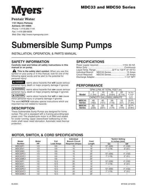
MDC33 and MDC50 Series1101 <strong>My</strong>ers ParkwayAshland, OH 44805Phone: 1-419-289-1144Fax: 1-419-289-6658Web Site: http://www.myerspump.com<strong>Submersible</strong> <strong>Sump</strong> <strong>Pumps</strong>INSTALLATION, OPERATION, & PARTS MANUALSAFETY INFORMATIONCarefully read and follow all safety instructions in thismanual or on pump.This is the safety alert symbol. When you see thissymbol on your pump or in this manual, look for one of thefollowing signal words and be alert to the potential forpersonal injury!warns about hazards that will cause seriouspersonal injury, death or major property damage if ignored.warns about hazards that can cause seriouspersonal injury, death or major property damage if ignored.warns about hazards that will or can causeminor personal injury or property damage if ignored.The word NOTICE indicates special instructions which areimportant but not related to hazards.DESCRIPTIONThese <strong>Submersible</strong> <strong>Sump</strong> <strong>Pumps</strong> are designed for homesumps. The unit is equipped with a 3-prong grounding-typepower cord. The shaded-pole motor is oil filled and sealedfor cooler running. Upper sleeve/lower ballbearing on themotor shaft never need lubrication. Automatic reset thermalprotection.SPECIFICATIONSPower supply required........................................115V, 60 HZ.Motor Duty ............................................................ContinuousLiquid Temp. Range ..........................32°F to 130°F (0°-54°C)Individual Branch MDC33 Series..........................15 AmpsCircuit Required: MDC50 Series..........................20 AmpsDischarge Adapter.................................................1-1/2" NPTPERFORMANCEGPM (LPM) AT TOTAL FEET (m)5 10 15 20Model (1.5m) (3m) (4.6m) (6.1m)CAPACITY GALLONS(L)/MINUTENo flowat heightshownbelowMDC33 48 40 29 15 24 Ft.Series (182) (151) (110) (57) (7.3m)MDC50 62 53 46 38 32 Ft.Series (235) (201) (174) (144) (9.8m)MOTOR, SWITCH, & CORD SPECIFICATIONSIndividual*Switch SettingModel Motor Full Branch Circuit Cord in inches (mm)Number HP Load Amps Required (Amps) Length On OffMDC33P1 1/3 9.8 15 10’ 13" (330) 4" (102)MDC33V1 1/3 9.8 15 10’ 7" (178) 2" (51)MDC33M1 1/3 9.8 15 10’ – –MDC33PC1 1/3 9.8 15 20’ 13" (330) 4" (102)MDC33VC1 1/3 9.8 15 20’ 7" (178) 2" (51)MDC33MC1 1/3 9.8 15 20’ – –MDC50P1 1/2 12.5 20 10’ 13" (330) 4" (102)MDC50V1 1/2 12.5 20 10’ 7" (178) 2" (51)MDC50M1 1/2 12.5 20 10’ – –MDC50PC1 1/2 12.5 20 20’ 13" (330) 4" (102)MDC50VC1 1/2 12.5 20 20’ 7" (178) 2" (51)MDC50MC1 1/2 12.5 20 20’ – –© 2005 MY506 (3/16/05)
GENERAL SAFETY INFORMATIONElectrically powered sump pumps normally give many yearsof trouble-free service when correctly installed, maintained,and used. However, unusual circumstances (interruption ofpower to the pump, dirt/debris in the sump, flooding thatexceeds the pump’s capacity, electrical or mechanical failurein the pump, etc.) may prevent your pump from functioningnormally. To prevent possible water damage due to flooding,consult your dealer about installing a secondary sump pump,a DC backup sump pump, and/or a high water alarm. See the“Troubleshooting Chart” in this manual for information aboutcommon sump pump problems and remedies. For more information,see your dealer.1. Know the pump application, limitations, and potentialhazards.2. Disconnect the power before servicing.3. Release all pressure within the system before servicingany component.4. Drain all water from the system before servicing.5. Secure the discharge line before starting the pump. Anunsecured discharge line will whip, possibly causing personalinjury and/or property damage.6. Check the hoses for a weak or worn condition beforeeach use. Make certain all connections are secure.7. Periodically inspect the sump, pump and system components.Keep free of debris and foreign objects. Performroutine maintenance as required.8. Provide a means of pressure relief for pumps whose dischargeline can be shut-off or obstructed.9. Personal Safety:a. Wear safety glasses at all times when working withpumps.b. Keep the work area clean, uncluttered and properlylighted – replace all unused tools and equipment.c. Keep visitors at a safe distance from work area.d. Make the workshop child-proof – with padlocks, masterswitches, and by removing starter keys.10. When wiring an electrically driven pump, follow all electricaland safety codes that apply.11. This equipment is only for use on 115 volt (singlephase) and is equipped with an approved 3-conductorcord and 3-prong, grounding-type plug.Electrical shock hazard. Can burn orkill. To reduce risk of electric shock, pull plug before servicing.Pump is supplied with a grounding conductor andgrounding-type attachment plug. Be sure it is connectedonly to a properly grounded grounding-type receptacle.Where a 2-prong wall receptacle is encountered, it mustbe replaced with a properly grounded 3-prong receptacleinstalled in accordance with codes and ordinances thatapply.This pump has not been investigated for use in swimmingpool areas.12. All wiring should be performed by a qualified electrician.13. Make certain the power source conforms to the requirementsof your equipment.14. Protect the electrical cord from sharp objects, hot surfaces,oil, and chemicals. Avoid kinking the cord. Replaceor repair damaged or worn cords immediately.15. Do not touch an operating motor. Motors can operate athigh temperatures.16. Do not handle the pump or pump motor with wet handsor when standing on wet or damp surface, or in water.Electrical shock hazard. Can burn or kill. Ifyour basement has water or moisture on floor, do not walk onwet area until all power has been turned off. If shut-off box isin basement, call electric company or hydro authority to shutoffservice to house, or call your local fire department forinstructions. Remove pump and repair or replace. Failure tofollow this warning can result in fatal electrical shock.17. Pump water only with this pump. Do not use with saltwater or brine.18. Do not install the pump in any location classified ashazardous by the National Electric Code, ANSI/NFPA70-1984 or the Canadian Electrical Code.INSTALLATION1. Install the pump in a sump pit with a minimum diameterof 10" (254mm) for models equipped with vertical switchesand 14" (356mm) for tethered float switch models. Thesump depth should be 15" minimum (381mm). Constructthe sump pit of tile, concrete, steel or plastic. Check thelocal codes for approved materials.2. The pump should not be installed on clay, earth or sand surfaces.<strong>Clean</strong> the sump pit of small stones and gravel whichcould clog the pump. Keep the pump inlet screen clear.3. Install the pump in the pit so that the switch operatingmechanism has maximum possible clearance.4. Install the discharge plumbing. When using rigid pipe,use plastic pipe. Wrap the threads with Teflon tape TM .Screw the pipe into the pump hand tight +1 – 1-1/2 turns.NOTICE: Do not use ordinary pipe joint compound onplastic pipe. Pipe joint compound can attack plastics anddamage the pump.Risk of flooding. If a flexible dischargehose is used, make sure the pump is secure in the sumpto prevent movement. Failure to secure the pump mayallow pump movement, switch interference and preventthe pump from starting or stopping.5. To reduce motor noise and vibrations, a short length ofrubber hose (e.g. radiator hose) can be connected intothe discharge line near the pump using suitable clamps.6. Install an in-line check valve to prevent backward flowthrough the pump when the pump shuts off.7. Power Supply: The pump is designed for 115 V., 60 Hz.,operation and requires a minimum 15 amp (1/3 HP) or 20amp (1/2 HP) individual branch circuit (refer to Motor,Switch and Cord Specifications chart, Page 1). Both thepump and switch are supplied with 3-wire cord sets withgrounding-type plugs. The switch plug is inserted directlyinto the outlet and the pump plug inserts into the oppositeend of the switch plug.Hazardous voltage. Can shock, burn orkill. The pump should always be electrically grounded toa suitable electrical ground such as a grounded waterpipe or a properly grounded metallic raceway, or groundwire system. Do not modify the cord or plug or cut off theround ground pin.8. If the pump discharge line is exposed to an outside subfreezingatmosphere, the portion of the line exposedmust be installed so any water remaining in the pipe willdrain to the outfall by gravity. Failure to do this can causethe water trapped in the discharge to freeze which couldresult in damage to the pump.9. After the piping and check valve have been installed, theunit is ready for operation.TME.I. DuPont de Nemours and Company Corporation.2
10. Check the operation by filling the sump with water andobserving pump operation through one complete cycle.Risk of Flooding. Failure to make thisoperational check may lead to improper operation, prematurefailure, and flooding.OPERATION / MAINTENANCERisk of electrical shock. Can burn or causedeath. Do not handle a pump or pump motor with wet handsor when standing on a wet or damp surface, or in water.Before attempting to check why unit has stopped operating,disconnect power from unit.Risk of fire and explosion. Can causesevere injury, property damage or death. Do not use inexplosive atmospheres. Pump water only with this pump.1. The shaft seal depends on water for lubrication and cooling.Do not operate the pump unless it is submerged inwater as the seal may be damaged if allowed to run dry.2. The motor is equipped with an automatic reset thermalprotector. If the temperature in the motor should riseunduly, the switch will cut off all power before damagecan be done to the motor. When the motor has cooledsufficiently, the switch will reset automatically and restartthe motor. If the protector trips repeatedly, the pumpshould be removed and checked as to cause of difficulty.Low voltage, long extension cords, clogged impeller, verylow head or lift, etc., could cause cycling.3. The pump will not remove all water. If a manually operatedpump is operating and suddenly no water comes outof the discharge hose, shut the unit off immediately. Thewater level is probably very low and the unit has brokenprime.3649 02003-1/2"(89 mm)Float Switch Tether Length, Models MDC33P1,MDC33PC1, MDC50P1 and MDC50PC1.NOTICE: Do not change the tether length of the float switch.The float must be able to swing through its complete arcwithout interference.AIRLOCKSWhen a pump airlocks, it runs but does not move any water.An airlock will cause the pump to overheat and fail. Thispump has a built in anti-airlock hole. See the exploded viewon the repair parts page for the location of the hole. Leakagefrom the anti-airlock hole is normal.If you suspect an airlock, unplug the pump, clean out theanti-airlock hole with a paper clip or a piece of wire, andrestart the pump.TROUBLESHOOTING CHARTSYMPTOM PROBABLE CAUSE(S) CORRECTIVE ACTIONPump won’t start Blown fuse. If blown, replace with a fuse of proper size.or run. Low line voltage. If the voltage is under the recommended minimum, check the sizeof the wiring from the main switch on the property. If OK, contactpower company or hydro authority.Defective motor.Replace the pump.Defective float switch. Replace the float switch.Impeller.If the impeller won’t turn, remove the lower pump body and locatethe source of the binding.Float is obstructed.Remove the obstruction.Pump starts and stops Backflow of water from Install or replace the check-valve.too often.piping.Faulty float switch.Replace the float switch.Pump won’t shut off. Defective float switch. Replace the float switch.Restricted discharge Remove the pump and clean the pump and piping.(obstacle in piping).Float obstructed.Remove the obstruction.Pump operates but Low line voltage. If the voltage is under the recommended minimum, check the sizedelivers little or noof the wiring from the main switch on the property. If OK, contactwater.power company or hydro authority.Something is caught in <strong>Clean</strong> out the impeller.impeller.Anti-airlock hole is plugged. Turn off the pump, clean out the anti-airlock hole, and restart pump.3
MDC33P1, MDC33PC1MDC33V1, MDC33VC1MDC33M1, MDC33MC1MDC50P1, MDC50PC1MDC50V1, MDC50VC1MDC50M1, MDC50MC11A1B1C234566A7A7B891D1011anti-airlock hole12A12B1314201516211E171F19184
REPLACEMENT PARTS LISTKey MDC33P1 MDC33PC1 MDC33V1 MDC33VC1 MDC33M1 MDC33MC1No. Description Qty. MDC50P1 MDC50PC1 MDC50V1 MDC50VC1 MDC50M1 MDC50MC11 Vertical Switch (Incl. 1A thru 1F) 1 – – PKG 208 PKG 209 – –1A Switch 11B Mounting Bracket 11C Screw 21D Float 11E Retainer Strap 11F Stop 12 Screw, #8-1/2” self-tapping (†) 1 U30-539SS U30-539SS U30-539SS U30-539SS – –3 Switch Cord Clamp (†) 1 CC0030-13 CC0030-13 – – – –4 Oil Fill Plug 1 U78-941ZPV U78-941ZPV U78-941ZPV U78-941ZPV U78-941ZPV U78-941ZPV5 Ring Handle 1 U97-128SS U97-128SS U97-128SS U97-128SS U97-128SS U97-128SS6 Cord Connector 1 PS17-46P PS17-46P PS17-46P PS17-46P PS17-46P PS17-46P6A O-Ring 1 U9-370 U9-370 U9-370 U9-370 U9-370 U9-3707A Motor Cover - DC Series 1 PS18-144B PS18-144B PS18-144B PS18-144B PS18-144B PS18-144B7B Motor Cover - EC Series PS18-149B PS18-149B – – PS18-149B PS18-149B8 #10-32 x3/4”, Capscrew 3 U30-482SS U30-482SS U30-482SS U30-482SS U30-482SS U30-482SS9 O-Ring 1 U9-339 U9-339 U9-339 U9-339 U9-339 U9-33910 Insulating Disk 1 PS18-82 PS18-82 PS18-82 PS18-82 PS18-82 PS18-8211 Motor / Upper Volute 1 * * * * * *12A Shaft Seal Stationary Head Assembly 1 U9-379A U9-379A U9-379A U9-379A U9-379A U9-379A12B Shaft Seal Rotating Mating Ring 1 U9-321A U9-321A U9-321A U9-321A U9-321A U9-321A13 Impeller 1 ** ** ** ** ** **14 Gasket 1 PS20-21 PS20-21 PS20-21 PS20-21 PS20-21 PS20-2115 Lower Volute 1 PS1-34P PS1-34P PS1-34P PS1-34P PS1-34P PS1-34P16 Lower Pump Body Screw #10-32x1”Hex Washer, self-tapping 7 U30-966SS U30-966SS U30-966SS U30-966SS U30-966SS U30-966SS17 Suction Plate 1 U43-142SS U43-142SS U43-142SS U43-142SS U43-142SS U43-142SS18 Screw, #6-1/4” pan head 1 U30-972SS U30-972SS U30-972SS U30-972SS U30-972SS U30-972SS19 Lower Pump Body Screw #10-32x1-1/8”Hex Washer, self-tapping 1 U30-967SS U30-967SS U30-967SS U30-967SS U30-967SS U30-967SS20 Powercord Assembly 1 See Chart See Chart See Chart See Chart See Chart See Chart21 Tethered Float Switch 1 PS217-62 PS217-64 – – – –Dielectric Oil All Models use .61 qts. 1 U197-8A U197-8A U197-8A U197-8A U197-8A U197-8A* If the Motor fails replace the entire pump.** The MDC33 Series pumps use Impeller number PS5-26P. MDC50 Series pumps use Impeller number PS5-29P.POWER CORD ASSEMBLYPump Part Pump PartModel Number Number Model Number NumberMDC33M1 PW117-281-TSU MDC50M1 PW117-237-TSUMDC33P1 PW117-281-TSU MDC50P1 PW117-237-TSUMDC33V1 PW117-281-TSU MDC50V1 PW117-237-TSUMDC33MC1 PW117-122-TSU MDC50MC1 PW117-122-TSUMDC33PC1 PW117-122-TSU MDC50PC1 PW117-122-TSUMDC33VC1 PW117-122-TSU MDC50VC1 PW117-122-TSU5
MYERS LIMITED WARRANTYDuring the time periods and subject to the conditions hereinafter set forth, F.E. <strong>My</strong>ers will repair or replace to the original user or consumer any portion of yournew MYERS product which proves defective due to defectivematerials or workmanship of MYERS. Contact your nearest Authorized MYERS Dealer for warranty service. At all times MYERS shall have and possess the soleright and option to determine whether to repair or replace defective equipment, parts, or components. Damage due to lightning or conditions beyond the controlof MYERS is NOT COVERED BY THIS WARRANTY.WARRANTY PERIOD<strong>Pumps</strong>: 12 months from date of installation or 18 months from date of manufacture.Tanks: 5 years from date of purchase.Labor, etc. Costs: MYERS shall IN NO EVENT be responsible or liable for the cost of field labor or other charges incurred by any customer in removing and/orre-affixing any MYERS product, part or component thereof.THIS WARRANTY WILL NOT APPLY: (a) to defects or malfunctions resulting from failure to properly install, operate or maintain the unit in accordance withprinted instructions provided; (b) to failures resulting from abuse, accident or negligence; (c) to normal maintenance services and the parts used in connectionwith such service; (d) to units which are not installed in accordance with applicable local codes, ordinances and good trade practices; or (e) unit is used for purposesother than for what it was designed and manufactured, and (f) if three-phase submersible motors are installed on a single-phase power supply using aphase converter or if three-phase power is supplied by only two transformers, making an open Delta system.RETURN OR REPLACED COMPONENTS: Any item to be replaced under this Warranty must be returned to MYERS in Ashland, Ohio, or such other place asMYERS may designate, freight prepaid.PRODUCT IMPROVEMENTS: MYERS reserves the right to change or improve its products or any portions thereof without being obligated to provide such achange or improvement for units sold and/or shipped prior to such a change or improvement.WARRANTY EXCLUSIONS: MYERS SPECIFICALLY DISCLAIMS THE IMPLIED WARRANTIES OF MERCHANTABILITY AND FITNESS FOR A PARTICULAR PUR-POSE AFTER THE TERMINATION OF THE WARRANTY PERIOD SET FORTH HEREIN.Some states do not permit some or all of the above warranty limitations and, therefore, such limitations may not apply to you. No warranties or representationsat any time made by any representative of MYERS shall vary or expand the provisions hereof.LIABILITY LIMITATION: IN NO EVENT SHALL MYERS BE LIABLE OR RESPONSIBLE FOR CONSEQUENTIAL, INCIDENTAL OR SPECIAL DAMAGES RESULT-ING FROM OR RELATED IN ANY MANNER TO ANY MYERS PRODUCT OR PARTS THEREOF. PERSONAL INJURY AND/OR PROPERTY DAMAGE MAYRESULT FROM IMPROPER INSTALLATION. MYERS DISCLAIMS ALL LIABILITY, INCLUDING LIABILITY UNDER THISWARRANTY, FOR IMPROPER INSTALLATION–MYERS RECOMMENDS FOLLOWING THE INSTRUCTIONS IN THE INSTALLATION MANUAL. WHEN INDOUBT, CONSULT A PROFESSIONAL.Some states do not allow the exclusion or limitation of incidental or consequential damages, so the above limitation or exclusion may not apply to you.This Warranty gives you specific legal rights and you may also have other rights which vary from state to state.In the absence of suitable proof of the purchase date, the effective date of this Warranty will be based upon the date of manufacture.DETERMINATION OF UNIT DATE OF MANUFACTURE: <strong>Submersible</strong> <strong>Sump</strong> Pump (8-95) month and year stamped on pump nameplate; Column <strong>Sump</strong> Pumpmonth and year on red warranty tag.MYERS1101 <strong>My</strong>ers Parkway, Ashland, Ohio 44805-1989Phone: 419-289-1144 • Fax: 419-289-6658 • www.femyers.com6