Installation Guide
Installation Guide
Installation Guide
- No tags were found...

You also want an ePaper? Increase the reach of your titles
YUMPU automatically turns print PDFs into web optimized ePapers that Google loves.
UniOPUniversal Operator Panels<strong>Installation</strong> <strong>Guide</strong>MANUUNIOP22- v.1.06 - 10.2002
UniOP TMUniversal Operator Panel<strong>Installation</strong> <strong>Guide</strong>Document code MANUUNIOP22Version 1.06Date 04.10.2002The contents of this manual have been checked for correctness and conformance tothe described equipment, Nevertheless it is not possible to guarantee the absence ofpossible discrepancies. The contents of the manual are checked on a regular basisand any necessary corrections are introduced in successive versions.Information in this document is subject to change without notice.No part of this manual may be reproduced or transmitted in any form or by anymeans, electronic or mechanical, for any purpose, without the prior writtenpermission of SITEK S.p.AWindows is a registered trademark of Microsoft Corporation.Copyright ? 2001 SITEK S.p.A. All rights reserved.SITEK S.p.A. - San Giovanni Lupatoto VR, Italy.Printed in Italy.
<strong>Installation</strong> <strong>Guide</strong><strong>Installation</strong> <strong>Guide</strong>ContentsIntroduction ................................................................................................1Product Identification .......................................................................3Technical Specifications..............................................................................3<strong>Installation</strong> ................................................................................................25Phisical Dimensions .......................................................................25Connections....................................................................................42Power Supply and Grounding .........................................................57PLC Port ........................................................................................58PC/Printer Port...............................................................................59AUX Port .......................................................................................61Models without the PC/Printer Port ................................................63External Keyboard Port ..................................................................63Battery Replacement.......................................................................64Removing the Legends ...................................................................65Dedicated LED’s ............................................................................66Usage and Safety <strong>Guide</strong>lines...........................................................67<strong>Installation</strong> Environment................................................................67Getting Started ..........................................................................................71Command Summary.......................................................................72Troubleshooting..............................................................................76Touchscreen Calibration .................................................................76i
UniOPii
<strong>Installation</strong> <strong>Guide</strong>IntroductionThis <strong>Installation</strong> <strong>Guide</strong> describes the main features of the UniOP operator panels.The <strong>Guide</strong> refers to the following models:BKDC-16BKDC-16TBKDC-46BKDL-16BKDL-16TBKDR-16BKDR-16TBKDR-46CP01F-02CP01R-04CP02F-02CP02R-04CP04F-04CP05R-04CP10G-04CP11G-04CP12G-04CP13G-04ECT-16ECT-VGAEF-02EF-04EL-16NELT-16ELT-VGAEL-VGAePAD30ePAD30TePAD31ePAD31TePAD32ePAD32TER-04ER-16ER-16TAER-25ER-25TOperator interface with color displayOperator interface with touch and color displayOperator interface with color displayOperator interface with EL displayOperator interface with touch and EL displayOperator interface with LCD displayOperator interface with touch and LCD displayOperator interface with LCD displayOperator interface with VFD displayOperator interface with LCD displayOperator interface with VFD displayOperator interface with LCD displayOperator interface with VFD displayOperator interface with LCD displayOperator interface with LCD displayOperator interface with LCD displayOperator interface with LCD displayOperator interface with LCD displayOperator interface with touch and color displayOperator interface with touch and VGA color displayOperator interface with VFD displayOperator interface with VFD displayOperator interface with EL displayOperator interface with touch and EL displayOperator interface with touch and VGA displayOperator interface with VGA displayOperator interface with TFT displayOperator interface with touch and TFT displayOperator interface with LCD displayOpertor interface with touch and LCD displayOperator interface with VGA displayOperator interface with touch and VGA displayOperator interface with LCD displayOperator interface with LCD displayOperator interface with touch and LCD displayOperator interface with LCD displayOperator interface with touch and LCD display1
UniOPERT-16 Operator interface with touch and LCD displayERT-VGA Operator interface with touch and VGA displayER-VGA Operator interface with VGA displayeTOP05 Operator interface with LCD 5”7 displayeTOP10 Operator interface with TFT 5”7 displayeTOP11 Operator interface with LCD 5”7 displayeTOP12 Operator interface with LCD B/W 5”7 displayeTOP30 Operator interface with TFT 10”4 displayeTOP31 Operator interface with LCD 10”4 displayeTOP32 Operator interface with VGA B/W 9”4 displayeTOP40 Operator interface with TFT 12”1 displayeTOP50 Operator interface with XGA TFT 15” displayETT-VGA Operator interface with touch and TFT color displayMD00G-04 Operator interface with LCD displayMD00R-02 Low-cost operator interface with LCD displayMD00R-04 Low-cost operator interface with LCD displayMD01R-02 Low-cost operator interface with LCD displayMD02F-02 Low-cost operator interface with VFD displayMD02G-04 Low-cost operator interface with LCD displayMD02R-04 Low-cost operator interface with LCD displayMD03R-02 Low-cost operator interface with LCD displayMD03R-04 Low-cost operator interface with LCD displayMKDC-VGA Operator interface with VGA color displayMKDC-VGA-T Operator interface with touch and VGA color displayMKDF-02 Operator interface with VFD displayMKDF-04 Operator interface with VFD displayMKDG-05 Operator interface with LCD displayMKDG-06 Operator interface with LCD displayMKDG-07 Operator interface with LCD displayMKDL-16N Operator interface with EL displayMKDL-VGA Operator interface with VGA displayMKDR-04 Operator interface with LCD displayMKDR-05 Operator interface with LCD displayMKDR-16 Operator interface with LCD displayMKDR-16TA Operator interface with touch and LCD displayMKDR-25 Operator interface with LCD displayMKDR-VGA Operator interface with VGA displayMKDR-VGA-T Operator interface with touch and VGA displayMKDT-VGA Operator interface with TFT color displayMKDT-VGA-T Operator interface with touch and TFT color displayTP01C-16 Operator interface with color display2
<strong>Installation</strong> <strong>Guide</strong>TP01R-16Operator interface with LCD displayThe products have been designed for installation in an industrial environ incompliance with the regulations:Emitted interference EN 50081-2, 1993Noise Immunity EN 61000-6-2, 2000In compliance with the above regulations the products are CE marked.Product IdentificationThe product may be identified through a plate attached to the rear cover. You willhave to know the type of unit you are using for correct usage of the informationcontained in the guide.An example of this plate is shown in the figure below:eTOP10-0050 product model name11/01 month/year of production13435 35508 serial numberH/W Vhardware version of the productS/W Vsoftware version of the productTechnical SpecificationsPower supply voltagePower consumptionDC 18 - 30 V(1)3
UniOPBack-up battery (1)Fuse3 V 270mA Lithium, not rechargeable,life about 1 year, user replaceable,model: CR2430.Change with same battery orequivalent with the work temperature of UniOP.2 A T user replaceable(except the models CP10G-04, CP11G-04,CP12G-04, CP13G-04, MKDG-06, MKDG-07,MD00G-04, MD00R-02/04, ePAD30,ePAD30T, ePAD31, ePAD31T, ePAD32,ePAD32T and eTOP05/10/11/12eTOP30/31/32/40/50 that are equipped with anovercurrent protection device)Environmental conditionsOperating temperature0 ? +50?C, with the exceptionof the model indicated on note(2)IEC 68-2-14Storage temperature -20 ? +70?C IEC 68-2-14Operating and storage humidity 5 ? 85 % RH not-condensing IEC 68-2-30Vibrations10 ? 57 Hz, 0,075 mm peak IEC 68-2-657 ? 150 Hz, 1 GShock 50 G, 11 ms, 3 pulses per axis IEC 68-2-27Protection class IP65 front panel (3) IEC 529Keyboard reliability> 3 million operationsTouch screen tecnologyresistiveTouch screen reliability> 1 million operationsElectromagnetic Compatibility (EMC)Emitted interference Class A EN 55011Immunity to radiated radiofrequencyelectromagnetic field80 MHz ? 1 GHz, 10 V/m900 MHz, 10V/mEN 61000-4-3ENV 50204Immunity to conducted disturbances 0.15 ? 80 MHz, 10 V EN 61000-4-6inducted by radiofrequency fieldFast transient2 KV power supplyEN 61000-4-41 KV signal linesElectrostatic discharge 8 KV in air EN 61000-4-2PC/Printer Port (1)RS-232connector D-sub 15 pin female300 - 38400 baud4
<strong>Installation</strong> <strong>Guide</strong>PLC PortRS-232, RS-422, RS-485, C.L. 20 mA (active),connector D-15 pin male300 - 38400 (1) baudAUX Portconnector D-9 pin female (functionality can beconfigured with an optional communicatinmodule)User memory(1)Recipe memory (1)16 KB / 32 KB RAM with back-up batteryHardware clock (1)Clock/Calendar with back-up batteryAlarms (1) 256/1024Historical event list (1)last 256/1024 events with back-up batteryProgramming software Designer version 5.08Notes:(1) feature depends on the panel models; see Table 1.(2) for models with “A1” suffix range 0 ? +70?C ,for models with “A5” suffix range -20 ? +70?Cfor eTOP and ePAD range 0 ? +45?C(3) all the installation instructions listed in the chapter ‘<strong>Installation</strong>Environment’ must be followed in detail.5
UniOPModel BKDC-16 BKDC-16T BKDC-46Display16x40 STNCOLOR16x40 STNCOLOR16x40 STNCOLORBacklight CCFL CCFL CCFLGraphics 320x240 320x240 320x240Display dimensions (mm) 121x91 121x91 121x91Diagonal (inches) 5.6” 5.6” 5.6”Character height (mm) - - -User memory 512KB 512KB 8MBUser memory expansion up to 1MB up to 1MB -Function keys 14 14 33System keys 23 23 24Touch screen - YES -User LED’s 11 11 24System LED’s 4 4 5PC/Printer Port YES YES YESPLC Port YES YES YESAUX Port (1) YES YES YESEsternal keyboard Port YES YES -Programming speed 9600-38400 9600-38400 9600-38400Battery YES YES YESRecipe memory 32KB 32KB 32KBAlarms 1024 1024 1024Events list 1024 1024 1024Hardware clock YES YES YESDownloadable characters 256 256 256Screen saver YES YES -YESBuzzer - - -Max current consumption on 24VDC (mA) 500 500 600Suffix 45: dimensions WxHxD (mm) (2) 216x168x82 216x168x82 275x220x79Suffix 50: dimensions WxHxD (mm) (3) - - -Max panel thickness (mm) 5 5 5Weight (Kg) 1.4 1.4 1.96Table 1 - UniOP Technical Data
<strong>Installation</strong> <strong>Guide</strong>BKDL-16 BKDL-16T BKDR-16 BKDR-16T BKDR-46 CP01F-0216x40 EL 16x40 EL 16x40 LCD 16x40 LCD 16x40 LCD 2x20 VFDCCFL CCFL CCFL CCFL CCFL LED320x240 320x240 320x240 320x240 320x240 -121x91 121x91 121x91 121x91 121x91 -5.6” 5.6” 5.6” 5.6” 5.6” -- - - - - 5512KB 512KB 512KB 512KB 8MB 512KBup to 1MB up to 1MB up to 1MB up to 1MB - up to 1MB14 14 14 14 33 523 23 23 23 24 19- YES - YES - -11 11 11 11 24 54 4 4 4 5 1YES YES YES YES YES YESYES YES YES YES YES YESYES YES YES YES YES YESYES YES YES YES - -9600-38400 9600-38400 9600-38400 9600-38400 9600-38400 9600-38400YES YES YES YES YES YES32KB 32KB 32KB 32KB 32KB 16KB1024 1024 1024 1024 1024 10241024 1024 1024 1024 1024 256YES YES YES YES YES YES256 256 256 256 256 -- - YES YES YES -- - - - - -800 800 500 500 600 300216x168x82 216x168x82 216x168x82 216x168x82 275x220x79 138x186x82- - - - - -5 5 5 5 5 51.4 1.4 1.4 1.4 1.9 1.1Table 1 - UniOP Technical Data7
UniOPModel CP01R-04 CP02F-02 CP02R-04Display 4x20 LCD 2x20 VFD 4x20 LCDBacklight LED LED LEDGraphics - - -Display dimensions (mm) - - -Diagonal (inches) - - -Character height (mm) 5 5 5User memory 512KB 512KB 512KBUser memory expansion up to 1MB up to 1MB up to 1MBFunction keys 5 16 16System keys 19 18 18Touch screen - - -User LED’s 5 16 16System LED’s 1 1 1PC/Printer Port YES YES YESPLC Port YES YES YESAUX Port (1) YES YES YESEsternal keyboard Port - - -Programming speed 9600-38400 9600-38400 9600-38400Battery YES YES YESRecipe memory 16KB 16KB 16KBAlarms 1024 1024 1024Events list 256 256 256Hardware clock YES YES YESDownloadable characters 8 - 8Screen saver - - -Buzzer - - -Max current consumption on 24VDC (mA) 250 300 250Suffix 45: dimensions WxHxD (mm) (2) 138x186x82 138x186x82 138x186x82Suffix 50: dimensions WxHxD (mm) (3) - - -Max panel thickness (mm) 5 5 5Weight (Kg) 1.1 1.1 1.18Table 1 - UniOP Technical Data
<strong>Installation</strong> <strong>Guide</strong>CP04F-04 CP05R-04 CP10G-04 CP11G-04 CP12G-04 CP13G-044x20 VFD 4x20 LCD 4x20 LCD 4x20 LCD 4x20 LCD 4x20 LCDLED LED LED LED LED LED- - 120x32 120x32 120x32 120x32- - 70x21 70x21 70x21 70x21- - 2.8” 2.8” 2.8” 2.8”5 5 - - - -512KB 512KB 512KB 512KB 512KB 512KBup to 1MB up to 1MB up to 1MB up to 1MB up to 1MB up to 1MB10 5 12 12 23 2319 19 23 23 24 24- - - - - -10 5 13 13 32 322 1 4 4 5 5YES - YES - YES -YES YES YES YES YES YESYES YES YES YES YES YES- - - - - -9600-38400 9600 9600-38400 9600 9600-38400 9600YES - YES - YES -16KB - 16KB - 16KB -1024 256 1024 256 1024 256256 - 256 - 256 -YES - YES - YES -- 8 256 256 256 256- - - - - -- - - - - -450 250 300 300 250 250168x216x82 138x186x82 141x176x76 141x176x76 275x220x76 275x220x76- - 141x176x80 141x176x80 275x220x85 275x220x855 5 5 5 5 51.3 1.1 1.1 1.1 2 2Table 1 - UniOP Technical Data9
UniOPModel ECT-16 ECT-VGA EF-02Display16x40 STN 30x80 STN 2x40 VFDCOLOR COLORBacklight CCFL CCFL CCFLGraphics 320x240 640x480 -Display dimensions (mm) 121x91 212x159 -Diagonal (inches) 5.6” 10.4” -Character height (mm) - - 5User memory 512KB 8MB 512KBUser memory expansion up to 1MB up to 1MBFunction keys - 8 -System keys - 3 5Touch screen YES YES -User LED’s - 8 -System LED’s 5 5 4PC/Printer Port YES YES YESPLC Port YES YES YESAUX Port (1) YES YES YESEsternal keyboard Port YES YES YESProgramming speed 9600-38400 9600-38400 9600-38400Battery YES YES YESRecipe memory 32KB 32KB 16KBAlarms 1024 1024 1024Events list 1024 1024 256Hardware clock YES YES YESDownloadable characters 256 256 -Screen saver YES YES -Buzzer YES - -Max current consumption on 24VDC (mA) 500 700 500Suffix 45: dimensions WxHxD (mm) (2) 216x168x82 311x220x89 311x111x89Suffix 50: dimensions WxHxD (mm) (3) - - -Max panel thickness (mm) 5 5 5Weight (Kg) 1.4 2.7 1.710Table 1 - UniOP Technical Data
<strong>Installation</strong> <strong>Guide</strong>EF-04 EL-16N ELT-16 ELT-VGA EL-VGA ePAD304x40 VFD 16x40 EL 16x40 EL 30x80 EL 30x80 30x80 TFTCCFL CCFL CCFL CCFL CCFL CCFL- 320x240 320x240 640x480 640x480 640X480- 121x91 121x91 212x159 212x159 218X159- 5.6” 5.6” 10.4” 10.4” 10.4”5 - - - - -512KB 512KB 512KB 8MB 8MB 8MBup to 1MB up to 1MB up to 1MB - - 16MB- - - 8 8 125 5 - 3 3 47- - YES YES - -- - - - 8 244 4 5 4 5 5YES YES YES YES YES YESYES YES YES YES YES YESYES YES YES YES YES YESYES YES YES YES YES -9600-38400 9600-38400 9600-38400 9600-38400 9600-38400 9600-38400YES YES YES YES YES YES16KB 32KB 32KB 32KB 32KB 32 KB1024 1024 1024 1024 1024 1024256 1024 1024 1024 1024 1024YES YES YES YES YES YES- 256 256 256 256 256- - - - - YES- - YES - - YES700 800 800 1300 1300 700311x111x89 311x165x89 216x168x82 311x220x89 311x220x89 -- - - - - 311x276x1005 5 5 5 5 51.9 2.4 1.4 2.7 2.7 2.7Table 1 - UniOP Technical Data11
UniOPModel ePAD30T ePAD31 ePAD31TDisplay 30x80 TFT 30x80 STNCOLOR30x80 STNCOLORBacklight CCFL CCFL CCFLGraphics 640X480 640X480 640X480Display dimensions (mm) 218X159 218X159 218X159Diagonal (inches) 10.4” 10.4” 10.4”Character height (mm) - - -User memory 8MB 8MB 8MBUser memory expansion 16MB 16MB 16MBFunction keys 12 12 12System keys 47 47 47Touch screen YES - YESUser LED’s 24 24 24System LED’s 5 5 5PC/Printer Port YES YES YESPLC Port YES YES YESAUX Port (1) YES YES YESEsternal keyboard Port - - -Programming speed 9600-38400 9600-38400 9600-38400Battery YES YES YESRecipe memory 32 KB 32 KB 32 KBAlarms 1024 1024 1024Events list 1024 1024 1024Hardware clock YES YES YESDownloadable characters 256 256 256Screen saver YES YES YESBuzzer YES YES YESMax current consumption on 24VDC (mA) 700 700 700Suffix 45: diemnsions WxHxD (mm) (2) - - -Suffix 50: diemnsions WxHxD (mm) (3) 311x276x100 311x276x100 311x276x100Max panel thickness (mm) 5 5 5Weight (Kg) 2.7 2.7 2.712Table 1 - UniOP Technical Data
<strong>Installation</strong> <strong>Guide</strong>ePAD32 ePAD32T ER-04 ER-16 ER-16TA ER-2530x80 LCD 30x80 LCD 4x40 LCD 16x40 LCD 16x40 LCD 25x80 LCDCCFL CCFL CCFL CCFL CCFL CCFL640X400 640X400 - 320x240 320x240 640x400218X159 218X159 - 121x91 121x91 194x12110.4” 10.4” - 5.6” 5.6” 9.6”- - 5 - - -8MB 8MB 512KB 512KB 512KB 512KB16MB 16MB up to 1MB up to 1MB up to 1MB12 12 - - - -47 47 5 5 5 5- YES - - YES -24 24 - - - -5 5 4 4 4 4YES YES YES YES YES YESYES YES YES YES YES YESYES YES YES YES YES YES- - YES YES YES YES9600-38400 9600-38400 9600-38400 9600-38400 9600-38400 9600-38400YES YES YES YES YES YES32 KB 32 KB 16KB 32KB 32KB 32KB1024 1024 1024 1024 1024 10241024 1024 256 1024 1024 1024YES YES YES YES YES YES256 256 8 256 256 256YES YES - YES YES YESYES YES - - - -700 700 400 500 500 600- - 311x111x89 311x165x89 311x165x89 311x220x89311x276x100 311x276x100 - - - -5 5 5 5 5 52.7 2.7 1.7 2.4 2.4 2.7Table 1 - UniOP Technical Data13
UniOPModel ER-25T ERT-16 ERT-VGADisplay 25x80 LCD 16x40 LCD 30x80 LCDBacklight CCFL CCFL CCFLGraphics 640x400 320x240 640x480Display dimensions (mm) 194x121 121x91 194x146Diagonal (inches) 9.6” 5.6” 9.6”Character height (mm) - - -User memory 512KB 512KB 2MBUser memory expansion up to 1MB up to 1MB -Function keys - - 8System keys 5 - 3Touch screen YES YES YESUser LED’s - - 8System LED’s 4 5 5PC/Printer Port YES YES YESPLC Port YES YES YESAUX Port (1) YES YES YESEsternal keyboard Port YES YES YESProgramming speed 9600-38400 9600-38400 9600-38400Battery YES YES YESRecipe memory 32KB 32KB 32KBAlarms 1024 1024 1024Events list 1024 1024 1024Hardware clock YES YES YESDownloadable characters 256 256 256Screen saver YES YES YESBuzzer - YES -Max current consumption on 24VDC (mA) 600 500 600Suffix 45: dimensions WxHxD (mm) (2) 311x220x89 216x168x82 311x220x89Suffix 50: dimensions WxHxD (mm) (3) - - -Max panel thickness (mm) 5 5 5Weight (Kg) 2.7 1.4 2.714Table 1 - UniOP Technical Data
<strong>Installation</strong> <strong>Guide</strong>ER-VGA eTOP05 eTOP10 eTOP11 eTOP12 eTOP3030x80 LCD 16X40 LCD 16X40 TFT 16X40 STN 16X40 LCD 30X80 TFTCOLORCCFL CCFL CCFL CCFL CCFL CCFL640x480 320x240 320x240 320X240 320X240 640X480194x146 121x91 121x91 121x91 121X91 218X1599.6” 5.7" 5.7" 5.7” 5.7” 10.4”- - - - - -2MB 8MB 8MB 8MB 8MB 8MB- - - - - -8 - - - - -3 - - - - -- YES YES YES YES YES8 - - - - -5 5 5 5 5 5YES YES YES YES YES YESYES YES YES YES YES YESYES YES YES YES YES YESYES - - - - -9600-38400 9600-38400 9600-38400 9600-38400 9600-38400 9600-38400YES YES YES YES YES YES32KB 32KB 32KB 32KB 32 KB 32 KB1024 1024 1024 1024 1024 10241024 1024 1024 1024 1024 1024YES YES YES YES YES YES256 256 256 256 256 256YES YES YES YES YES YES- YES YES YES YES YES600 600 600 600 600 700311x220x89 - - - - -- 187x147x71 187x147x95 187x147x95 187x147x95 287x232x955 5 5 5 5 52.7 1.4 1.4 1.4 1.4 2.25Table 1 - UniOP Technical Data15
UniOPModel eTOP31 eTOP32 eTOP40Display30X80 STN 30X80 LCD 40X100 TFTCOLORBacklight CCFL CCFL CCFLGraphics 640x480 640X480 800X600Display dimensions (mm) 218x159 218x159 246x184Diagonal (inches) 10.4" 10.4” 12.1”Character height (mm) - - -User memory 8MB 8MB 8MBUser memory expansion - - -Function keys - - -System keys - - -Touch screen YES YES YESUser LED’s - - -System LED’s 5 5 5PC/Printer Port YES YES YESPLC Port YES YES YESAUX Port (1) YES YES YESEsternal keyboard Port - - -Programming speed 9600-38400 9600-38400 9600-38400Battery YES YES YESRecipe memory 32KB 32KB 32 KBAlarms 1024 1024 1024Events list 1024 1024 1024Hardware clock YES YES YESDownloadable characters 256 256 256Screen saver YES YES YESBuzzer YES YES YESMax current consumption on 24VDC 700 700 800(mA) Suffix 45: dimensions WxHxD (mm) (2) - - -Suffix 50: dimensions WxHxD (mm) (3) 287x232x95 287x232x95 337x267x95Max panel thickness (mm) 5 5 5Weight (Kg) 2.25 2.25 2.8516Table 1 - UniOP Technical Data
<strong>Installation</strong> <strong>Guide</strong>eTOP50 ETT-VGA MD00G-04 MD00R-02 MD00R-04 MD01R-0248X128 TFT 30x80 TFT 4x20 LCD 2x20 LCD 4x20 LCD 2x20 LCDCCFL CCFL LED LED LED LED1024X768 640x480 120x32 - - -304X228 194x146 70x21 - - -15” 9.6” 2.8” - - -- - - 6 5 68MB 512KB 512KB 512KB 512KB 512KB- - - - - -- 8 4 4 4 4- 3 7 7 7 7YES YES - - - -- 8 5 5 5 45 6 4 4 4 2YES YES - - - -YES YES YES YES YES YESYES YES YES YES YES YES- YES - - - -9600-38400 9600-38400 9600 9600 9600 9600YES YES - - - -32 KB 32KB - - - -1024 1024 256 256 256 2561024 1024 - - - -YES YES - - - -256 256 256 8 8 8YES YES - - - -YES - - - - -1200 700 250 250 250 250- 311x220x89 149x109x65 149x109x65 149x109x65 195x98x82392x307x104 - - - - 195x98x905 5 5 5 5 53.85 2.7 1 0.9 0.9 0.9Table 1 - UniOP Technical Data17
UniOPModel MD02F-02 MD02G-04 MD02R-04Display 2x20 VFD 4x20 LCD 4x20 LCDBacklight CCFL LED LEDGraphics - 120x32 -Display dimensions (mm) - 70x21 -Diagonal (inches) - 2.8” -Character height (mm) 5 - 5User memory 512KB 512KB 512KBUser memory expansion - - -Function keys 9 9 9System keys 10 10 10Touch screen - - -User LED’s 9 9 9System LED’s 2 2 2PC/Printer Port YES YES YESPLC Port YES YES YESAUX Port (1) YES YES YESEsternal keyboard Port - - -Programming speed 9600-38400 9600-38400 9600-38400Battery YES YES YESRecipe memory 16KB 16KB 16KBAlarms 1024 1024 1024Events list 256 256 256Hardware clock YES YES YESDownloadable characters - 8 8Screen saver - - -Buzzer - - -Max current consumption on 24VDC 300 250 250(mA) Suffix 45: dimensions WxHxD (mm) (2) 195x98x82 195x98x82 195x98x82Suffix 50: dimensions WxHxD (mm) (3) - - 195x98x90Max panel thickness (mm) 5 5 5Weight (Kg) 0.9 0.9 0.918Table 1 - UniOP Technical Data
<strong>Installation</strong> <strong>Guide</strong>MD03R-02 MD03R-04 MKDC-VGA MKDC-VGA- MKDF-02 MKDF-042x20 LCD 4x20 LCD 30x80 STN 30x80 T STN 2x40 VFD 4x40 VFDCOLOR COLORLED LED CCFL CCFL LED LED- - 640x480 640x480 - -- - 212x159 212x159 - -- - 10.4” 10.4” - -6 5 - - 5 5512KB 512KB 8MB 8MB 512KB 512KB- - - - 1024KB 1024KB9 9 26 26 16 1610 10 25 25 29 29- - - YES - -9 9 26 26 24 242 2 4 4 5 5- - YES YES YES YESYES YES YES YES YES YESYES YES YES YES YES YES- - YES YES YES YES9600 9600 9600-38400 9600-38400 9600-38400 9600-38400- - YES YES YES YES- - 32KB 32KB 16KB 16KB256 256 1024 1024 1024 1024- - 1024 1024 256 256- - YES YES YES YES8 8 256 256 - -- - YES YES - -- - - - - -250 250 700 700 500 700195x98x82 195x98x82 311x276x89 311x276x89 311x165x89 311x165x89195x98x90 195x98x90 - - - -5 5 5 5 5 50.9 0.9 3.5 3.5 1.9 1.9Table 1 - UniOP Technical Data19
UniOPModel MKDG-05 MKDG-06 MKDG-07Display 8x40 LCD 8x40 LCD 8x40 LCDBacklight CCFL CCFL CCFLGraphics 240x64 240x64 240x64Display dimensions (mm) 127x34 127x34 127x34Diagonal (inches) 5.2” 5.2” 5.2”Character height (mm) 5 - -User memory 512KB 512KB 512KBUser memory expansion 1024KB 1024KB up to 640 KBFunction keys 20 23 23System keys 18 24 24Touch screen - - -User LED’s 26 24 32System LED’s 4 5 5PC/Printer Port YES YES YESPLC Port YES YES YESAUX Port (1) YES YES YESEsternal keyboard Port - - -Programming speed 9600-38400 9600-38400 9600-38400Battery YES YES YESRecipe memory 16KB 16KB 16KBAlarms 1024 1024 1024Events list 256 256 256Hardware clock YES YES YESDownloadable characters - 256 256Screen saver - - -Buzzer - - -Max current consumption on 24VDC (mA) 400 400 400Suffix 45: dimensions WxHxD (mm) (2) 311x111x89 220x176x76 275x220x76Suffix 50: dimensions WxHxD (mm) (3) - 220x176x85 275x220x85Max panel thickness (mm) 5 5 5Weight (Kg) 1.9 1.2 220Table 1 - UniOP Technical Data
<strong>Installation</strong> <strong>Guide</strong>MKDL-16N MKDL-VGA MKDR-04 MKDR-05 MKDR-16 MKDR-16TA16x40 EL 30x80 4x40 LCD 4x40 LCD 16x40 LCD 16x40 LCDCCFL CCFL LED LED CCFL CCFL320x240 640x480 - - 320x240 320x240121x91 212x159 - - 121x91 121x915.6” 10.4" - - 5.6” 5.6”- - 5 5 - -512KB 8MB 512KB 512KB 512KB 512KBup to 1MB - up to 1MB up to 1MB up to 1MB up to 1MB16 26 16 20 16 1619 24 29 18 19 19- - - - - YES24 26 24 26 24 245 5 5 4 5 5YES YES YES YES YES YESYES YES YES YES YES YESYES YES YES YES YES YESYES YES YES YES YES YES9600-38400 9600-38400 9600-38400 9600-38400 9600-38400 9600-38400YES YES YES YES YES YES32KB 32KB 16KB 16KB 32KB 32KB1024 1024 1024 1024 1024 10241024 1024 256 256 1024 1024YES YES YES YES YES YES256 256 8 8 256 256- - - - YES YES- - - - - -800 1300 400 350 500 500311x220x89 311x276x76 311x165x89 311x111x89 311x220x89 311x220x89- - - - - -5 5 5 5 5 52.5 3.5 1.9 1.8 2.5 2.5Table 1 - UniOP Technical Data21
UniOPModel MKDR-25 MKDR-VGA MKDR-VGA-TDisplay 25x80 LCD 30x80 30x80Backlight CCFL CCFL CCFLGraphics 640x400 640x480 640x480Display dimensions (mm) 194x121 194x146 194x146Diagonal (inches) 9.6” 9.6” 9.6”Character height (mm) - - -User memory 512KB 8MB 8MBUser memory expansion up to 1MB - -Function keys 26 26 26System keys 24 24 24Touch screen - - YESUser LED’s 26 26 26System LED’s 4 5 5PC/Printer Port YES YES YESPLC Port YES YES YESAUX Port (1) YES YES YESEsternal keyboard Port YES YES YESProgramming speed 9600-38400 9600-38400 9600-38400Battery YES YES YESRecipe memory 32KB 32KB 32KBAlarms 1024 1024 1024Events list 1024 1024 1024Hardware clock YES YES YESDownloadable characters 256 256 256Screen saver YES YES YESBuzzer - - -Max current consumption on 24VDC (mA) 600 600 600Suffix 45: dimensions WxHxD (mm) (2) 311x276x89 311x276x89 311x276x89Suffix 50: dimensions WxHxD (mm) (3) - - -Max panel thickness (mm) 5 5 5Weight (Kg) 3.5 3.5 3.522Table 1 - UniOP Technical Data
MKDT-VGA MKDT-VGA-T TP01C-16 TP01R-1630x80 30x80 16x40 STN 16x40 LCDCOLORCCFL CCFL CCFL CCFL640x480 640x480 320x240 320x240212x159 212x159 121x91 121x9110.4” 10.4” 5.6” 5.6”- - - -8MB 8MB 512KB 512KB- - up to 1MB up to 1MB26 26 30 3024 24 25 25- YES - -26 26 32 325 5 4 4YES YES YES YESYES YES YES YESYES YES YES YESYES YES YES YES9600-38400 9600-38400 9600-38400 9600-38400YES YES YES YES32KB 32KB 32KB 32KB1024 1024 1024 10241024 1024 1024 1024YES YES YES YES256 256 256 256YES YES YES YES- - - -700 700 500 500311x276x89 311x276x89 220x311x89 220x311x89- - - -5 5 5 53.5 3.5 2.5 2.5<strong>Installation</strong> <strong>Guide</strong>Table 1 - UniOP Technical Data23
UniOPNotes :HW(1) With optional module.(2) Suffix 45: for operator panel which have suffix A1, A5, 45.(3) Suffix 50: for operator panel which have suffix 50.24
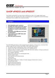
<strong>Installation</strong> <strong>Guide</strong><strong>Installation</strong>UniOP panels are designed to be mounted on the front of some type of enclosure.The bezel height, bezel width and the cut-out dimensions for each panel type aregiven in the following pages.Note: remove the red BATTERY PROTECTION strip before istallationPhisical DimensionsAll measurements are given in mm, with tolerance ±0.5.MD00G-04, MD00R-02, MD00R-04109mm4.29"149mm5.86"5mm0.19"96mm3.78"136mm5.35"Figure 1 - Dimensions25
UniOPMD01R-02, MD02F-02, MD02G-04, MD02R-04, MD03R-02, MD03R-0498mm3.85"195mm7.67 "8mm0.31"4x 4. 2mm0.16"5.0mm0.20 "87mm3.43"174mm6.85 "4.5mm0.18 "184mm7.24 "A = 74mm 2.91” for operator panel which have suffix A1, A5, 45.82mm 3.2” for operator panel which have suffix 50Figure 2 - Dimensions26
<strong>Installation</strong> <strong>Guide</strong>CP10G-04, CP11G-04176mm6.93"141mm5.55"5mm0.2"163mm6.41"128mm5.04"A = 71mm 2.8” for operator panel which have suffix A1, A5, 45.75mm 2.9” for operator panel which have suffix 50Figure 3 - Dimensions27
UniOPCP01F-02, CP01R-04, CP02F-02, CP02R-04, CP05R-04138mm5.43"5.5mm0.22 "176mm6.93 "165mm6.50 "5.5mm0.22 "186mm7.32 "8mm0.31"4x 4.2mm0.16 "117mm4.61 "128mm5.04 "Figure 4 - Dimensions28
<strong>Installation</strong> <strong>Guide</strong>CP04F-04216mm8.50 "168mm6.61 "4x 4.2mm0.16 "5mm0.20 "8mm0.31 "205mm8.07 "195mm7.67 "5mm0.20 "147mm5.79 "157mm6.18 "Figure 5 - Dimensions29
UniOPBKDC-16, BKDC-16T, BKDL-16, BKDL-16T, BKDR-16, BKDR-16T, ECT-16, ELT-16, ERT-1630Figure 6 - Dimensions
<strong>Installation</strong> <strong>Guide</strong>BKDC-46, BKDR-46220mm8.66 “275mm10.82”4mm0.16 "262mm10.31”206mm8.11 “Figure 7 - Dimensions31
UniOPEF-02, EF-04, ER-04, MKDR-05, MKDG-05311mm12.25 "80mm3.15 "9mm0.35 "92mm3.62 "111mm4.37 "292mm11.50 "Figure 8 - DimensionsEL-16N, ER-16, ER-16TA, MKDF-02, MKDF-04, MKDR-04147mm5.79 "165mm6.50 "311mm12.25 "80mm3.15 "9mm0.35 "292mm11.50 "Figure 9 - Dimensions32
<strong>Installation</strong> <strong>Guide</strong>eTOP05147 mm5.79”187 mm7.36”4 mm0.16”67 mm2.63”176 mm6.9”136 mm5.35”Figure 10 - Dimensions33
UniOPeTOP10, eTOP11, eTOP12147 mm5.79”187 mm7.36”91 mm3.56”4 mm0.16”176 mm6.9”136 mm5.35”34Figure 11 - Dimensions
<strong>Installation</strong> <strong>Guide</strong>eTOP30, eTOP31, eTOP32232 mm9.13”287 mm11.29”91 mm3.56”4 mm0.16”276 mm10.86”221 mm8.7”Figure 12 - Dimensions35
UniOPeTOP40267 mm10.51”337 mm13.26”91 mm3.56”4 mm0.16”326 mm12.83”256 mm10.07”Figure 13 - Dimensions36
<strong>Installation</strong> <strong>Guide</strong>eTOP50307 mm12.08”392 mm15.43”100 mm3.95”4 mm0.16”381 mm14.99”296 mm11.65”Figure 14 - Dimensions37
UniOPMKDG-06176mm6.93"220mm8.66"5mm0.2"163mm6.41"207mm8.15"A = 71mm 2.8” for operator panel which have suffix A1, A5, 45.80mm 3.1” for operator panel which have suffix 50.38Figure 15 - Dimensions
<strong>Installation</strong> <strong>Guide</strong>CP12G-04, CP13G-04, MKDG-07220mm8.66"AB B B B B B275mm10.82"5mm0.2"207mm8.15"262mm10.35"A = hole for switch, 22mm diameter.B = holes for switches, 16mm diameter.C = 71mm 2.8” for operator panel which have suffix A1, A5, 45.80mm 3.1” for operator panel which have suffix 50.Figure 16 - Dimensions39
UniOPECT-VGA, ELT-VGA, EL-VGA, ER-25, ER-25T, ER-VGA,ERT-VGA, ETT-VGA, MKDL-16N, MKDR-16, MKDR-16TA,TP01R-16, TP01C-16.Note: TP01C-16 and TP01R-16 dimensions are the same as shown below, butrotated 90 degrees so that the height and width dimensions are reversed.220mm8.66 "311mm12.25"9mm0.35 "202mm7.95 "292mm11.50 "Figure 17 - Dimensions40
<strong>Installation</strong> <strong>Guide</strong>MKDC-VGA, MKDC-VGA-T, MKDL-VGA, MKDR-25, MKDR-VGA, MKDR-VGA-T, MKDT-VGA, MKDT-VGA-T276mm10.86 "311mm12.25 "80mm3.15 "9mm0.35 "257mm10.12 "292mm11.50"Figure 18 - Dimensions41
UniOPePAD30, ePAD30T, ePAD31, ePAD31T, ePAD32, ePAD32T.276 mm10.86”311 mm12.25”292 mm11.5”96 mm3.76”4 mm0.16”257 mm10.2”42
<strong>Installation</strong> <strong>Guide</strong>Figure 19 - Dimensions43
UniOPConnectionsMD00G-04, MD00R-02, MD00R-04Figure 20 - ConnectorsMD01R-02, MD03R-02, MD03R-04Figure 21 - Connectors44
<strong>Installation</strong> <strong>Guide</strong>MD02F-02, MD02R-04Figure 22 - ConnectorsMD02G-04POWERAUX PORTPLC PORTPC/PRINTER PORTFigure 23 - Connectors45
UniOPCP05R-04PLC PORTFUSEAUX PORTPOWERFigure 24 - ConnectorsCP01F-02, CP01R-04, CP02F-02, CP02R-04Figure 25 - Connectors46
<strong>Installation</strong> <strong>Guide</strong>CP11G-04Figure 26 - Connectors47
UniOPCP10G-04Figure 27 - ConnectorsCP04F-04, CP04F-04GFigure 28 - Connectors48
<strong>Installation</strong> <strong>Guide</strong>BKDC-16, BKDC-16T, BKDL-16, BKDL-16T, BKDR-16, BKDR-16T,ECT-16, ELT-16, ERT-16POWER FUSEAUX PORT PLC PORT PC/PRINTER PORTEXTERNAL KEYBOARD PORTFigure 29 - ConnectorsMKDG-06Figure 30 - Connectors49
UniOPeTOP05POWERAUX PORT PLC PORT PC PRINTERFigure 31 - ConnectorseTOP10, eTOP11, eTOP12, eTOP30, eTOP31, eTOP32, eTOP40, eTOP50POWERAUX PORT PLC PORT PC PRINTERFigure 32 - Connectors50
<strong>Installation</strong> <strong>Guide</strong>EF-02, EF-04, ER-04, MKDR-05, MKDG-05POWERFUSEAUX PORTEXTERNAL KEYBOARD PORTPLC PORTPC/PRINTER PORTFigure 33 - ConnectorsEL-16, EL-16N, ER-16, ER-16TA, MKDF-02, MKDF-04, MKDR-04POWERFUSEAUX PORTEXTERNAL KEYBOARD PORTPLC PORTPC/PRINTER PORTFigure 34 - Connectors51
UniOPBKDC-46, BKDR-46FUSEPOWERAUX PORTPLC PORT PC PRINTERFigure 35 - Connectors52
<strong>Installation</strong> <strong>Guide</strong>ECT-VGA, EL-25, EL-25T, ELT-VGA, EL-VGA, ER-25, ER-25T, ER-VGA,ERT-VGA, ETT-VGA, MKDL-16, MKDL-16N, MKDR-16, MKDR-16TA,TP01C-16, TP01R-16POWERFUSEAUX PORTEXTERNAL KEYBOARD PORTPLC PORTPC/PRINTER PORTFigure 36 - Connectors53
UniOPCP13G-04Figure 37 - ConnectorsCP12G-04, MKDG-07Figure 38 - Connectors54
<strong>Installation</strong> <strong>Guide</strong>MKDC-VGA, MKDC-VGA-T, MKDL-25, MKDL-VGA, MKDR-25, MKDR-VGA, MKDR-VGA-T, MKDT-VGA, MKDT-VGA-TFUSEPOWERAUX PORT PLC PORTEXTERNAL KEYBOARD PORTPC/PRINTER PORTFigure 39 - Connectors55
UniOPePAD30, ePAD30T, ePAD31, ePAD31T, ePAD32, ePAD32T.POWERAUX PORTPLC PORT PC PRINTERFigure 40 - Connectors56
Power Supply and Grounding<strong>Installation</strong> <strong>Guide</strong>The power supply terminal block is shown in the figure below. The terminal block isincluded with the panel.Figure 41 - Power supply terminal blockNote: ensure that the power supply has enough power capacity for theoperation of the equipment.The unit must always be grounded to protection earth (PE). Grounding helps limitthe effects of noise due to electromagnetic interference on the control system.Earth connection will have to be done using either either the screw or the fastonterminal located near the power supply terminal block. A yellow label help identifythe ground connection. Also connect to ground the terminal 3 on the power supplyterminal block.The power supply circuit may be floating or grounded. In the latter case connect toground the power source common as shown in figure 42 with a dashed line.When using the floating power scheme, note that the panels internally connect thepower commond to ground with a 1 M? resistor in parallel with a 10 nF capacitor.The power supply must have double or reinforced insulationThe suggested wiring for the power supply is shown in figure 42.57
UniOPL1NPEACDCPANELL+MFigure 42 - Power supplyAll the electronic devices in the control system must be properly grounded.Grounding must be performed according to applicable regulations.PLC PortThe PLC Port is used to communicate with the PLC or with another type ofcontroller; if the panel is configured as an UniNET client, then this port may be usedfor the network connection.Different electrical standards are available for the signals in the PLC port connector:RS-232, RS-422, RS-485 or Current Loop 20 mA. The cable used selects theappropriate signals. It is always necessary to use the correct cable type for on thePLC to be connected.Note: If the proper cable is not used, communication with the PLC will not bepossible.The connector is a D-15 pin male. Pin assignment is shown in the table below.58
<strong>Installation</strong> <strong>Guide</strong>Pin Description1 Frame Ground2 RXD3 TXD4 +5 V output (Max 100mA)5 GND6 CHA-7 CHB-8 TX+ 20 mA9 TX- 20 mA10 RTS11 CTS12 RX+ 20 mA13 RX- 20 mA14 CHA+15 CHB+Figure 43 - PLC Port connector and pin assignmentThe communication cable must be chosen for the type of device being connected.PC/Printer PortThe function of the PC/Printer Port depends on the mode of operation of the panel.Configuration Modeprogramming portOperation Mode, UniNET Serverconnection to UniNETOperation Mode, UniNET not active or Client node connection to serialprinterOnly RS232 signals are available on the PC/Printer Port. The connector is a D-15 pifemale. Pin assignment is shown in the table below.59
UniOPPin Description1 Frame Ground2 RXD3 TXD4 +5 V output (max 100mA)5 GND6 Riserved7 Riserved8 Riserved9 Riserved10 RTS11 CTS12 Riserved13 Riserved14 Riserved15 RiservedFigure 44 - PC/Printer Port connector and pin assignmentUse cable CA2 to connect the panel to a PC for programming. The diagram isshown in the figure below. The connector is a D-9 pin female.60
<strong>Installation</strong> <strong>Guide</strong>Figure 45 - Programming cable CA2Figure 46 - Programming cable CA114When the panel is in Operation Mode and is not as a UniNET Server, you can attacha serial printer to the PC/Printer Port. The communication parameters for the printerare defined by the application program (project file)Note: the communication cable to the printer depends on the communicationinterface of the printer.AUX PortThe AUX Port is a communication port specially designed for industrial networkcommunication. The AUX Port connector is a 9 pin D sub type. The functionality ofthe AUX Port depends on the optional communication module which is plugged intothe unit.Note: The pin assignment of the Aux Port connector is described in the manualof the communication module.61
UniOPThe procedure to mount the communication modules is the following:1) turn off the unit2) partially unscrew with a screwdriver the 2 screws holding the rear cover. Thescrews are labelled ‘A’ in Figure 473) remove the cover (for eTOP05/10/11/12/30/31/32/40/50 and ePAD30, ePAD30T,ePAD31, ePAD31T, ePAD32, ePAD32T lever with screwdriver on the slot onthe cover’s side).4) plug the module in the red connectors; make sure the connectors are locked5) replace the rear cover6) fix the 2 screws ‘A’ (for eTOP05/10/11/12/30/31/32/40/50 and ePAD30,ePAD30T, ePAD31, ePAD31T, ePAD32, ePAD32T close the cover with a littlepressure).7) stick in the area ‘B’ the label describing the functionality of the AUX Port. Thelabel is delivered with the modulesAAFigure 47 - Mounting the communication modules62
<strong>Installation</strong> <strong>Guide</strong>Models without the PC/Printer PortSome UniOP models, see Table 1, do not have the PC/Printer Port. The PLC Portwill be referred to as the PLC/PC Port, and will be used as a programming portwhen the panel is in Configuration Mode. You must use a gender changer with theCA2/CA114 cable to program these units.External Keyboard PortSeveral UniOP models, see Table 1, are equipped with a connector designed toconnect an external keyboard type ET-F or AT-F. The communication cable comeswith the keyboards.63
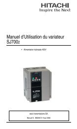
UniOPBattery ReplacementSome models require the use of the lithium battery for data back-up.The following information is maintained by the battery:?? hardware real-time clock (date and time)?? event list?? recipe dataUniOP panels signal the battery status in more than one way:?? blinking of the LED indicator FAULT or FLT (when available) or?? with the ‘Battery’ field in System Menu (BATTERY OK or LOW)?? with the value of the S6 bit in the RDAWhen the panel signals that the battery is low, you should replace the battery as soonas possible.Note: Replacing the battery will cause the loss of the data maintained by thebattery.To replace the battery, follow the procedure listed below:Battery64Figure 48 - battery replacement
<strong>Installation</strong> <strong>Guide</strong>1) turn off the power to the panel2) use a screwdriver to loose the four screws securing the block composed by thetwo metal units3) remove the block4) remove the battery5) replace the battery with a new oneNote:CAUTION! Danger of explosion if battery is incorrectly replaced.Replace only with the same or equivalent type recommended by themanufacturer.Dispose of used batteries according to the manufaturer’sinstructions.6) replace the block; tighten the four screws7) apply power to the panel and check that battery good status is signaled.Removing the LegendsThe keyboard legends can be removed in one step by grasping the exposed portion ofthe legend and sliding it downward.Use the blank legends that come with the panel or other with equivalent thicknessand consistency. Do not use legends thicker than ones included in the panel.65
UniOPDedicated LED’sThe table below shows the name and the symbol (when available) of the LED’sdedicated to special functions which may be available in the UniOP operator panels.LEDName/symbol Color Status MeaningFAULT/FLT red OFF No hardware problem detected;battery OKRUN /BLINKONBattery lowHardware faultDL green OFF No keys are pressed and no errorsBLINKONCommunication error (not allmodels)While any key is pressed (visualfeedback)red OFF No hardware problem detectedBLINKONBattery lowHardware faultgreen OFF No keys are pressedONgreen OFF Hardware faultONWhile any key is pressed (visualfeedback)Unit in operationCOM / green BLINK Communication errorONCommunication OKALARM / red OFF No alarms!BLINKONAlarm requires acknowledgmentAlarm activeTable 2 - Dedicated LED’s66
<strong>Installation</strong> <strong>Guide</strong>Usage and Safety <strong>Guide</strong>linesApplicable RegulationsRegulations and recommendations have been issued in Europe covering the mainsafety-related issues in control systems which include operator interfaces.EN 60204-1 lists some important guidelines applicable when using operatorinterfaces.9.2.4 Suspension of safeguards9.2.5.3 Stop9.2.5.4 Emergency stop9.2.5.6 Hold-to-run controls9.2.5.7 Two-hand controls9.4 Control function in case of failureDo not use operator interface to directly command motors, valves or other actuatorsnot equipped with safeguards and potentially harmful to persons or equipment incase of fault to the unit.The units are intended to be monted on the front panel of a metallic cabinet. Theservice personnel, when operating directly on the powered unit, must beelectrostatically discharged.All safety related regulations must be observedCAUTION! Don’t open the panel rear cover when the power supply is applied.<strong>Installation</strong> EnvironmentThe equipment is not intended for continuous exposure to direct sunlight This mightaccelerate the aging process of the front panel film.The equipment is not intended for installation in contact with corrosive chemicalcompounds. Check the resistance of the front panel film to a specific compoundbefore installation.Do not use tools of any kind (screwdrivers, etc.) to operate the keyboard of the panelor the touch screen.67
UniOPIn order to meet the front panel protection classifications, proper installationprocedure must be followed:?? the borders of the cutout must be flat?? screw up each fixing screw until the plastic bezel corner get in contact with thepanel.?? The cutout for the panel must be of the dimensions indicated in this manual.?? Two types of gaskes are delivered with the UniOP panels, depending on themodel, rectangular or linear.Applying the rectangular gasket?? The gasket should be applied around the cutout prepared for the panel beingcareful not to place it under tension?? The gasket should be replaced every time that the panel is dismounted andremounted in its placeGASKETCUT-OUTUniOP PANELFigure 49 - panel with rectangular gasket installation68
<strong>Installation</strong> <strong>Guide</strong>Applying the two linear gaskets:Thin strip:?? The gasket should be applied around the cutout prepared for the panel?? The gasket should be applied starting from the middle of the lower side beingcareful not to place it under tension?? The two ends of the gasket should meet without overlap?? The gasket should be replaced every time that the panel is dismounted andremounted in its placeLarge strip:?? The gasket should be applied on the operator panel just behind the bezel?? The gasket should be applied starting from the 1/3 of the lower side beingcareful not to place it under tension?? The two ends of the gasket should meet without overlap?? The gasket should be replaced every time that the panel is dismounted andremounted in its placeCUT-OUTLARGE STRIP1/2THIN STRIPFigure 50 - panel with linear gaskets installation69
UniOPCleaning FaceplatesThe equipment must be cleaned only with a soft cloth and neutral soap product. Donot use solvents.Handling the Memory CardsThe SSFDC memory cards used in some of the UniOP operator panels need to behandled with care when replaced in the memory slot of the panel.Figure 51 – SSFDC memory cardBefore inserting the memory card in its slot in the panel, the contact area must beverified to be clean. Any track of contaminants such as oil or any greasy substancesshould be carefully removed.Contamination on the golden contacts of the memory card, at the moment the mediais inserted in the slot, may generate an insulating layer that may result in electricalcontact problems with the sliding elements of the socket.Corrosive / active chemicals may permanently damage the memory card goldensurface. Any contact with such substances must be carefully avoided.To ensure the proper operation of the memory media the contact surface of theSSFDC card should be cleaned with a soft, clean tissue.Note: The use of any synthetic cloth could permanently damage the memorycard due to electrostatic discharge.70
<strong>Installation</strong> <strong>Guide</strong>Direct contact with the human body (fingers) with the contact area should becarefully avoided.In case the memory card needs to be removed from the slot and carried around, ithas to be kept in a special antistatic protective case.Getting StartedUniOP panels must be programmed with the programming package Designer.To program a panel you will have to connect the panel to a personal computerrunning Designer software package; the panel must be in Configuration mode to beprogrammed. Use the cable CA2/CA114 to connect the panel to a personalcomputer.The software package Designer is a Windows TM application and must be properlyinstalled. The Windows TM environment is not included in the software packageDesigner and must already be installed on the personal computer.The software package can use either the communication ports COM1 or COM2 onthe personal computer. Check that the Designer program is correctly configured tocomunicate with the communication port to which the cable attached.The communication parameters between the panel and the personal computer are:speed: 9600 (models PC/Printer Port support also speeds of19200 and 38400 baud )parity: nonestop bit: 1The Designer software defaults to the correct parameters.The version of the Designer being used must be compatible with the firmwareversion of the panel to be programmed. Call for more information on compatibilitybetween firmware and programming software.71
UniOPCommand SummaryThe chapter describes the keyboard commands recognized by UniOP panels.Commands are classified according to the operating modes of the unit.Note: The standard command assignment is described in this chapter. All thecommands, except those defined for Configuration Mode, can be charged,deleted and/or extended using the Keyboard Macro Editor facility of theprogramming software.Some models ado not have CLEAR key on the keyboard; the corresponding functioncam be done pressing the keys ? e ? at the same time.Some models are designed to be attached to an external keyboard of type ET-F orAT-F; the commands describes in this chapter are generally referring to the use ofan external keyboardAll the UniOP models, except the ECT-16, ELT-16, ERT-16 and ECT-VGA, haveat least 4 arrow keys and the Enter key. Panels with touch screen will show systemdefined touch keys on the screen whenever it is required (Figure 52).CLEAR ENTERFigure 52 - Default touch keys for the panels with touchscreenSome of the keys described in this chapter may not be available in each UniOPmodel. The functions associated to them may, however, be implemented using theKeyboard Macro Editor or using an alternative predefined key.Models without numeric keypad and without touch screen allow numeric data entryusing arrow keys and/or using the Keyboard Macro Editor.Touch screen panels will show automatically a numeric keypad whenever the dataentry phase is activated.Note: the text ‘2 s’ associated to a key means that the key has to be held for twoseconds to activate the associated function.72
Configuration ModeENTERENTER 2 sOperation Mode<strong>Installation</strong> <strong>Guide</strong>shows the type and version of the communication driver stored inthe unit (if any)returns to Operation Mode if a valid communication driver and avalid project are stored in the unit (the key must be pressed for 2seconds)? scroll page up? scroll page down? previous page? next pageENTER 2 s recall the Command Menu0/INS enter Data Entry ModeInsenter Data Entry Mode9/PRN print page/cancel printPrt Scr print page/cancel printENABLE 2 s recall Direct Access Mode6/(2) recall Password Insert Mode3/(2) recall Date/Time Insert ModeTo recall the Configuration Mode in the models ECT-16 , ELT-16 , ERT-16 andECT-VGA touch the screen in an area where no touch cells have been defined andhold for 2 seconds.Command Menu? select up? select down? select left? select rightENTER activate selectionCLEAR (1) return to Page ModeSystem Menu? select up? select down? activate selection? activate selectionENTER return to Page Mode when EXT is selected73
UniOPCLEAR (1)return to Page ModeData Entry ModeWhen in Data Entry Mode the meaning of the keys changes depending on wheter afield has been selected for Data Entry or not. A field is selscted when The DataEntry procedure has been started on that field. If not field has already been selectedfor Data Entry, the key assignment is shown in the table below.? move to field in previous row? move to field in next row? previous field? next fieldInsnext field0?9 . +/- select field a numeric field for Data Entry and enter numeric valueENTER select a field for Data EntryCLEAR (1) cancel entry and return to Page ModeAfter a field has been selected for Data Entry, the keys are interpreted as follows.? increment digit / scroll up ASCII / select message up? increment digit / scroll down ASCII / select message down? move cursor left in ASCII field? move cursor right in ASCII field0?9 . +/- numeric entryENTER confirm entry and return to Page ModeCLEAR (1) cancel entry and return to Page ModeAlarm Mode? previous alarm in the list? next alarm in the listENTER 2 s acknowledge current alarmCLEAR (1) return to page Mode9/PRN alarm list printout/cancel printPrt Alm alarm list printout/cancel printPrt Scr alarm list printout/cancel printEvent Mode? scroll up? scroll downCLEAR (1) return to page Mode9/PRN event list printout/cancel printPrt Alm event list printout/cancel print74
<strong>Installation</strong> <strong>Guide</strong>Prt Screvent list printout/cancel printPassword Entry Mode? increment digit? decrement digit? next digit0?9 numeric password entryENTER confirm password and return to Page ModeCLEAR (1) cancel entry and return to Page ModeESC end entry and return to Page ModeTime and Date Set Mode? increment field value? decrement field valueENTER field selectCLEAR (1) return to Page ModeDirect Page Selection Mode? decrement page? increment page0?9 page number entryENTER confirm entry and go to selected pageCLEAR (1) cancel entry and return to Page ModeDirect Acces Mode? decrement offset? increment offset0?9 numeric offset entryENTER select next, confirm offset entryCLEAR (1) cancel numeric offset entry end return to Page ModeTselect timersZselect countersEselect digital inputsAselect digital outputsMselect flags/merkersENABLE return to Page ModeNotes:(1) it is equivalent to the key ESC/ , when available75
UniOP(2) available only in the models BKDx-16, CP10G-04, CP12G-04,MKDG-06, MKDG-07, MKDx-25 and MKDC-VGA.TroubleshootingIn the case it might be impossible to switch the operator panel to ConfigurationMode due to problems in the start-up phase, follow the procedure described below:1. Switch off the unit2. Press and hold any 3 keys3. Turn on the unit and hold the keys pressed until Configuration Mode will beshown on the screen.For keyless models such as the ECT-16, ELT-16, ERT-16, follow the procedurebelow:1. Switch off the unit2. Touch in the middle of the left side of the display screen with the left hand3. Switch on the operator panel and tap with the right hand in the middle of theright side of the display screen with a period of about one second.4. Continue until the screen will show Configuration ModeTouchscreen CalibrationStandard calibration:1. Recall Configuration Mode2. Touch the CLEAR key on the screen until a small round symbol will appear onthe top right corner of the screen3. touch and hold the symbol until it will move to the low lef corner of the screen4. touch and hold the symbol until the indication to touch the ? key will bedisplayed on the screen5. touch and hold the key ? until the indication to touch the ? key will bedisplayed on the screen6. touch and hold the key ? until the indication to touch the Enter key will bedisplayed on the screen7. touch and hold the Enter key until the panel will switch to Operation Mode (if avalid project is loaded in the memory)Emergency calibration.The Emergency calibration procedure should be used in all cases when it wouldresult not possible to go to calibration using the standard procedure.1. Switch of the unit2. turn on the unit3. tap in the middle of the touchscreen with a frequency of about one second untilthe operator panel will enter the Calibration Mode76
<strong>Installation</strong> <strong>Guide</strong>4. perform the standard calibration procedure.77