BOP Handling Systems - Ingersoll Rand
BOP Handling Systems - Ingersoll Rand
BOP Handling Systems - Ingersoll Rand
- No tags were found...

You also want an ePaper? Increase the reach of your titles
YUMPU automatically turns print PDFs into web optimized ePapers that Google loves.
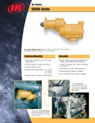
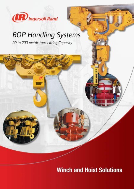
<strong>BOP</strong> <strong>Handling</strong> <strong>Systems</strong>20 to 200 metric tons Lifting CapacityWinch and Hoist Solutions
Table of Contents1. <strong>BOP</strong> <strong>Handling</strong> <strong>Systems</strong> – Overview.......................................................................32. <strong>BOP</strong> <strong>Handling</strong> <strong>Systems</strong> – Selection Chart............................................. 43. Hercu-Link Air <strong>BOP</strong> <strong>Handling</strong> <strong>Systems</strong> (20 to 200 tons Capacity) Standard Features and Options......................................................................... 5 Specifications and Performance of Piston Motor Drive ..................................6 Model Driver...................................................................................................... 7 Dimensions and Drawings.......................................................................... 12-134. Liftchain <strong>BOP</strong> <strong>Handling</strong> <strong>Systems</strong> (25 to 200 tons Capacity) Standard Features and Options......................................................................... 8 Liftchain Air <strong>BOP</strong> <strong>Handling</strong> <strong>Systems</strong>• Specifications and Performance of Gear Motor Drive.............................9• Model Driver............................................................................................ 11• Dimensions and Drawings................................................................. 14-18 Liftchain Hydraulic <strong>BOP</strong> <strong>Handling</strong> <strong>Systems</strong>• Specifications and Performance.............................................................10• Model Driver............................................................................................ 11• Dimensions and Drawings................................................................. 14-185. Engineered Solutions BHS150M and BHS200M series....................................................................... 19 ULBS100LCA4 series (Ultra-low headroom design).......................................196. Contact Information Worldwide Locations........................................................................................ 202
<strong>BOP</strong> <strong>Handling</strong> <strong>Systems</strong>OVERVIEWFor over 30 years <strong>Ingersoll</strong> <strong>Rand</strong> has designed, manufactured, and serviced hundreds of Blowout Preventer <strong>Handling</strong> <strong>Systems</strong> for all themajor drilling contractors and oil companies in the industry.Our familiarity with this complex and critical lifting application enables us to provide the type of equipment, engineering support, andcertifications that these projects require.The design of our <strong>BOP</strong> <strong>Handling</strong> <strong>Systems</strong> reflects the years of experience we’ve gained by providing equipment for the harshestenvironments and applications around the world. Our Oilfield Tough systems feature compact modular designs, robust “bulletproof”gearboxes, powerful air or hydraulic motors, large diameter load chain, and all steel/cast iron construction which provides increasedsafety, rugged reliability, enhanced control, and reduced maintenance.OverviewOur commitment to safety and quality combined with our long experience with difficult lifting applications allows us to provide our clientswith the safest and most cost-effective solutions possible.The <strong>Ingersoll</strong> <strong>Rand</strong> Advantage 3rd Party approvals by one or more regulatory bodies; the American Bureau of Shipping (ABS), Det Norske Veritas (DNV),Lloyds Register of Shipping (LRS), Norwegian Petroleum Directorate (NPD), European Machinery Directives (CE).ISO 9001 certified manufacturing and service facilitiesCertificate No. FM53539Certificate No. QUAL/1991/309e 5:1 design factor combined with all steel and cast iron construction to withstand the brutalenvironmental and mechanical challenges of the job. Automatic multi-disc oil bath motor brakes that engage instantly the moment the controls are released. High efficiency planetary gearboxes that are fully sealed to exclude contaminants. Space saving modular designs require no deck space, offer low headroom and improved end approach.Ultra‐low headroom models are available for applications with severe envelope restrictions. Air and hydraulic powered models to choose from, including high-torque radial piston and compact (lube-free)gear type air motors. Air motors provide built-in overload protection since they will stall without damaging hoist. Smooth, precise, and safe load control with variable speed pendent control. Rugged corrosion resistant load chain in 16, 22, and 32 mm sizes has greater elongation and therefore, ismore resistant to shock loading. The large links provide for easier external inspection, excellent resistance to abrasion, andwill last indefinitely when properly maintained. True vertical lift which enhances load control characteristics and safety. Articulated trolleys accommodate limited side pulling as <strong>BOP</strong> stack is being lifted. Engineered options• Rack and pinion trolley drive option for positive traction and improved horizontal load control.• Severe duty packages available for cold weather, marine, and explosion-proof environments including ATEX.• Remote control pendents and consoles.• Spark and corrosion resistant components.• Air and hydraulic festooning systems.• Trolleys for custom fabricated beams.• Clevis and shackle bottom block assemblies.• Low pressure 4 bar (57psi) applications.3
<strong>BOP</strong> <strong>Handling</strong> <strong>Systems</strong>SELECTION CHART**Rated capacity Model Number Number of Chain Falls Max. lifting speed Minimum Headroom(tons) per hoist m/min (ft/min) mm (in.)Hercu-Link Air <strong>BOP</strong> <strong>Handling</strong> <strong>Systems</strong> (Piston motor drive)Selection Chart2030405075100150200BHS20M 2 1.5 (5) 813 (32)BHS30M 3 1 (3.8) 895 (35.25)BHS40M-4 4 0.8 (2.5) 903 (35.56)BHS40M-8 4 0.8 (2.5) 903 (35.56)BHS50M 2 1.2 (4) 1040 (40.94)BHS75M 3 0.8 (2.5) 1243 (48.94)BHS100M 4 0.6 (2) 1346 (53)BHS150M 3 0.7 (2.5) –BHS200M 4 0.6 (2) –Liftchain Air <strong>BOP</strong> <strong>Handling</strong> <strong>Systems</strong> (Gear motor drive)2530365075100150200BS25LCA2P 2 0.8 (2.63) 1128 (44.41)BS30LCA3P 3 0.6 (1.97) 1242 (48.9)BS36LCA3P 3 0.5 (1.64) 1242 (48.9)BS50LCA2P 2 1.6 (5.25) 976 (38.42)BS50LCA4P 4 0.4 (1.30) 1290 (50.79)BS75LCA3P 3 1.1 (3.60) 1170 (46.06)BS100LCA4P 4 0.8 (2.60) 1392 (54.8)BS150LCA3P 3 0.4 (1.30) 1845 (72.64)BS200LCA4P 4 0.3 (0.98) 1901 (74.84)Liftchain Hydraulic <strong>BOP</strong> <strong>Handling</strong> <strong>Systems</strong>2530365075100150200BS25LCH2P 2 2.8 (9.19) 1128 (44.41)BS30LCH3P 3 1.9 (6.23) 1242 (48.9)BS36LCH3P 3 1.86 (6.1) 1242 (48.9)BS50LCH2P 2 2.27 (7.45) 976 (38.42)BS50LCH4P 4 1.35 (4.1) 1290 (50.79)BS75LCH3P 3 1.51 (4.95) 1170 (46.06)BS100LCH4P 4 1.13 (3.7) 1392 (54.8)BS150LCH3P 3 0.48 (1.57) 1845 (72.64)BS200LCH4P 4 0.36 (1.18) 1901 (74.84)**All <strong>BOP</strong> <strong>Handling</strong> <strong>Systems</strong> are comprised of two trolley-mounted hoists; each of which is rated at one-half thecomplete system capacity.4
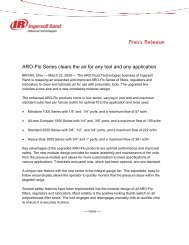
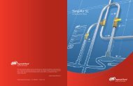
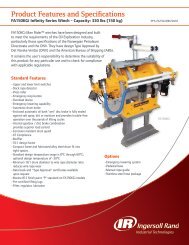
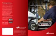
Hercu-Link Air <strong>BOP</strong> <strong>Handling</strong> <strong>Systems</strong>STANDARD FEATURES AND OPTIONS of Piston Motor Drive – 20 to 200 tons Lifting CapacityDesigned to meet or exceed specifications of one or more of thefollowing regulatory bodies – the Norwegian Petroleum Directorate(NPD), UK HSE, Lloyds Register of Shipping (LRS), Det NorskeVeritas (DNV), and American Bureau of Shipping (ABS) for theoilwell drilling industry.Standard Features• Radial piston air motor – hoist and trolley• 5:1 design factor• All steel construction• Automatic Fail- Safe, multi disc, motor brake on hoist• Articulated trolley allows limited side pulling operations on8‐wheel trolley models• Fully enclosed planetary gear box• Compact modular design• Corrosion resistant load chain• 9m (30 ft) height of lift standard on all models• Bottom block mounted on bearing with external lubrication pointand water drain• Accu-Trol pendent with “emergency stop/start” feature and9m (30 ft) pendent hose• Limit switch for upper and lower over-travel protection.• Lifting lugs for easy installation• Filter-Lubricator air preparation package mounted on unit• Corrosion resistant Marine 812 finish paint• Galvanized steel chain container• Trolley guide rollers, rubber bumpers, and rail sweeps• Manufacturer test certificate and maintenance manual• Exhaust mufflersBHS100M (100‐ton system) in the process of deploying BlowoutPreventer stackHercu-Link AirOptions• Variable lengths of lift and pendent control hose• Spark and corrosion resistant (S•COR•E) packages• Rack and pinion trolley drive for positive traction• Clevis and shackle attachment in lieu of bottom hook• Air or hydraulic festooning systems• Trolleys for shipyard fabricated beams• CE compliant models including overload protection andmain emergency stop device• Corrosion resistant Marine 812-X paint system• Sandblast and carbozinc (primer only)• Custom paint coating systems per owners specifications• Custom designed air control consoles• 4 bar (57 psi) application modelsBHS50M (50‐ton system) after storage of Blowout Preventer forperiodic maintenance.5
Hercu-Link Air <strong>BOP</strong> <strong>Handling</strong> <strong>Systems</strong>SPECIFICATIONS AND PERFORMANCE of Piston Motor Drive – 20 to 200 tons Lifting CapacityHercu-Link AirHoist SpecificationsModel System Standard lift/ Speed of hoist Hoist Air inlet Chain Chain wt./lineal Chain Net weightNo. capacity Pendent drop lift lower motor NPT Size m (ft) of lift falls per of system(tons) m ft m/min fpm m/min fpm hp cfm in. mm kg lbs hoist kg lbsBHS20M 20 9 30 1.5 5 2.3 7.5 3.8 165 3/4 16 x 45 11 25 2 1183 2600BHS30M 30 9 30 1 3.8 1.5 5 3.8 165 3/4 16 x 45 17 38 3 1706 3750BHS40M-4 40 9 30 0.8 2.5 1.1 3.8 3.8 165 3/4 16 x 45 23 50 4 2230 4900BHS40M-8 40 9 30 0.8 2.5 1.1 3.8 3.8 165 3/4 16 x 45 23 50 4 2662 5850BHS50M 50 9 30 1.2 4 1.8 6 9.4 280 1" 22 x 66 21 47 2 2616 5750BHS75M 75 9 30 0.8 2.5 1.1 3.8 9.4 280 1" 22 x 66 32 71 3 2844 6250BHS100M 100 9 30 0.6 2 0.9 3 9.4 280 1" 22 x 66 43 94 4 4527 9950BHS150M 150 9 30 0.7 2.5 - - 25 700 1"1/2 32 x 90 68 151 3 3526 7750BHS200M 200 9 30 0.6 2 - - 25 700 1"1/2 32 x 90 91 201 4 5005 11000Notes:Air supply hose size must be a minimum 0.25 inch larger dia. than air inlet size.Performance figures are at 7.3 bar (105 psi) air pressure.Trolley SpecificationsModel No. of pairs Flange Wheel tread Wheel loading Min. inside Trolley SpeedNo. of wheels adjustment diameter per pair curve radius motor of Trolleyper beam mm in. mm in. kg lbs mm in. hp cfm m/min fpmBHS20M 2 152-203 6-8 175 6.13 5310 11670 1524 (1) 60 (1) 1.6 65 0-12 0-40BHS30M 2 152-203 6-8 175 6.88 7940 17450 2133 (1) 84 (1) 1.6 65 0-12 0-40BHS40M-4 2 152-203 6-8 229 9 10579 23250 1829 (1) 72 (1) 1.6 65 0-12 0-40BHS40M-8 4 152-203 6-8 175 6.88 5346 11750 - - 1.6 65 0-12 0-40BHS50M 4 152-203 6-8 175 6.88 6552 14400 - - 1.6 65 0-12 0-40BHS75M 4 203-254 8-10 229 9 9896 21750 - - 1.6 65 0-12 0-40BHS100M 4 203-254 8-10 229 9 13104 28800 - - 1.6 65 0-12 0-40BHS150M 8 203-254 8-10 229 9 9896 21750 - - 1.6 65 0-12 0-40BHS200M 8 203-254 8-10 229 9 13104 28800 - - 1.6 65 0-12 0-40(1) Without trailing trolley or with articulated trolley.WARNING:This equipment isnot to be used forlifting, supporting ortransporting people,or lifting or supportingloads over people.Standard Equipment:Trolley BumpersLimit SwitchPiston Motor TrolleyCorrosion resistantload chainGalvanized steelchain containerMufflerAir prep packageDisc brake systemAccu-Trol pendent handle6
Hercu-Link Air <strong>BOP</strong> <strong>Handling</strong> <strong>Systems</strong>MODEL DRIVER of Piston Motor Drive – 20 to 200 tons Lifting CapacityHow to OrderSpecify the complete model as shown. Specify beam size, type and flange width.Example: BHS40MA6-30-30-8KRSeriesBHSBHS = BlowoutPreventer<strong>Handling</strong>SystemSystemCapacity40tons lbs # of hoists x cap.20 = 44,000 (2 x 10 tons)30 = 66,000 (2 x 15 tons)40 = 88,000 (2 x 20 tons)50 = 110,000 (2 x 25 tons)75 = 165,000 (2 x 37.5 tons)100 = 220,000 (2 x 50 tons)150 = 330,000 (2 x 75 tons)200 = 440,000 (2 x 100 tons)SuspensionMP = Plain TrolleyG = Geared TrolleyM = Piston Motor TrolleyR = Rack and Pinion DriveTrolley flangeadjustmentA = standardB = 2” extensionC = 4" extensionD = 6” extensionControl -5 = 1 Mtr. Pendent(2 button w/on-off)6 = 2 Mtr. Pendent(4 button w/on-off)7 = 3 Mtr. Pendent(6 button w/on-off)Notes:M1 – Material traceability certificates according to EN 10204 (Ex DIN 50049) 2.2 on load bearing parts. Thisconformity document affirms (by the manufacturer) that parts are in compliance with the requirements ofthe order based on non-specific inspection and testing (i.e. results are typical material properties for theseparts).M2 – Material traceability certificates according to EN 10204 (Ex DIN 50049) 3.1b on load bearing parts.These documents affirm (by a department independent of the manufacturing department) that the actual partsused in the product are in compliance with the order based on specific inspection and testing (i.e. results areactual material properties for those parts).M3 – Material traceability certificates according to EN 10204 (Ex DIN 50049) 3.1b on load bearing parts.These documents affirm (by a department independent of the manufacturing department) that the actual partsused in the product are in compliance with the order based on specific inspection and testing (i.e. results areactual material properties for those parts in a finished, as delivered condition).WARNING: Standard Hercu-Link hoists purchased for <strong>BOP</strong> handling systemswill void the warranty.They are not designed for this type of application.A6-Lift30XX = Lengthof lift8 = 8 Wheel trolley--ControldropXX = Control drop pendentand or hand chain dropOptions4 = 4 Wheel trolley40 ton systems are available with either 4 or 8 wheeltrolleys and must be specified in model code. 20 and 30ton systems have 4 wheels trolleys. 50, 75 and 100 tonsystems have 8 wheel trolleys. 150 and 200 ton systemshave 16 wheel trolleys.C1 = ABS minus 20˚C design temperature (tD)C2 = DNV minus 20˚C design temperature (tD)F = Type approval; please specify in text:ABS or DNVK = Clevis (in place of bottom hook)M1 = Per DIN 50049/EN10204 Para 2.2 “Typicals”M2 = Per DIN 50049/EN10204 Para 3.1b actual per product aspurchasedM3 = Per DIN 50049/EN10204 Para 3.1b actual per product asdelivered in final conditionP1 = Marine 812-X paint systemR = Copper plated (S•COR•E package)The product will be equipped with copper plated loadhook(s) and trolley wheels. Zinc plated load and handchain if applicable.S = Solid bronze (S•COR•E package)Up to 40 ton systems will be equipped with solid bronzetrolley wheelsW1 = ABS witness testW2 = DNV witness testW3 = LRS witness testW4 = Customer witness testX = Special testing; please specifyZ = Sandblast and carbozinc (primer only)-E = Compliance withEC Machinery Directives**30-- 8KRHercu-Link Air Model Driver**CE package includes:- Overload protection- Emergency stop button- Main air shut-off valve- CE declaration of conformity7
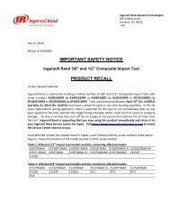
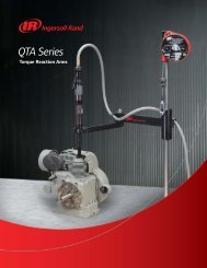
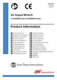
Liftchain Air or Hydraulic <strong>BOP</strong> <strong>Handling</strong> <strong>Systems</strong>STANDARD FEATURES AND OPTIONS – 25 to 200 tons Lifting CapacityDesigned to meet or exceed specifications of one or more of thefollowing regulatory bodies - the Norwegian Petroleum Directorate(NPD), UK HSE, Lloyds Register of Shipping (LRS), Det NorskeVeritas (DNV), and American Bureau of Shipping (ABS) for theoilwell drilling industry.Standard FeaturesLiftchain• Gear type air motor – hoist and trolley• 5:1 design factor• All steel/cast iron construction• Automatic Fail Safe multi disc, motor brake on hoist and trolley• Articulated trolley allows limited side pulling operations• Fully enclosed planetary gear box• Compact modular design• Corrosion resistant load chain• 9m (30 ft) height of lift standard on all models• Bottom block mounted on bearing with external lubrication pointand water drain• 9m (30 ft) of control (progressive pendent)• Limit switch for upper and lower over-travel protection.• Lifting lugs for easy installation• Filter-Lubricator-Regulator air preparation package mounted on unit• Corrosion resistant Marine 812 finish paint• Galvanized steel chain container• Trolley guide rollers, rubber bumpers, and rail sweeps• Manufacturer test certificate and maintenance manual• Exhaust mufflersBS75LCA3 (75-ton) air system – 1 hoist shownOptions• Variable lengths of lift and pendent control hose• Spark and corrosion resistant (S•COR•E) packages• Rack and pinion trolley drive for positive traction• Clevis and shackle attachment in lieu of bottom hook• Air or hydraulic festooning systems• Trolleys for shipyard fabricated beams• CE compliant models including overload protection andmain emergency stop device• Corrosion resistant Marine 812-X paint system• Sandblast and carbozinc (primer only)• Custom paint coating systems per owners specifications• Custom designed hydraulic and air control consolesBS75LCH3 (2 x 75-ton) hydraulic systems used on a rig8
Liftchain Air <strong>BOP</strong> <strong>Handling</strong> <strong>Systems</strong>SPECIFICATIONS AND PERFORMANCE of Gear Motor Drive – 25 to 200 tons Lifting CapacityHoist SpecificationsModel System Standard lift/ Speed of hoist Hoist Air inlet Chain Chain wt./lineal Chain Net weightNo. capacity Pendent drop lift lower motor BSP Size m (ft) of lift falls per of system(tons) m ft m/min fpm m/min fpm hp cfm in. mm kg lbs hoist kg lbsBS25LCA2P 25 9 30 0.8 2.63 1.50 4.92 4 163 3/4 16 x 45 11 25 2 800 1760BS30LCA3P 30 9 30 0.6 1.97 1.00 3.28 4 163 3/4 16 x 45 17 38 3 970 2134BS36LCA3P 36 9 30 0.5 1.64 1.00 3.28 4 163 3/4 16 x 45 17 38 3 970 2134BS50LCA2P 50 9 30 1.6 5.25 2.50 8.20 10 406 1"1/4 22 x 66 21 47 2 1130 2486BS50LCA4P 50 9 30 0.4 1.30 0.75 2.46 4 163 3/4 16 x 45 23 50 4 1040 2288BS75LCA3P 75 9 30 1.1 3.60 1.70 5.58 10 406 1"1/4 22 x 66 32 71 3 4000 8800BS100LCA4P 100 9 30 0.8 2.60 0.90 2.95 10 406 1"1/4 22 x 66 43 94 4 4400 9680BS150LCA3P 150 9 30 0.4 1.30 0.48 1.57 10 406 1"1/4 32 x 90 68 151 3 9440 20768BS200LCA4P 200 9 30 0.3 0.98 0.35 1.16 10 406 1"1/4 32 x 90 91 201 4 9990 21978Notes:Air supply hose size must be a minimum 0.25 inch larger dia. than air inlet size.Trolley SpecificationsModel No. of pairs Flange Wheel tread Wheel loading Min. inside Trolley SpeedNo. of wheels adjustment diameter per pair curve radius motor of Trolleyper beam mm in. mm in. kg lbs mm in. hp cfm m/min fpmBS25LCA2P 2 131-310 5-12 160 6.30 6250 13750 3 118 2 81 12 39BS30LCA3P 2 131-310 5-12 225 8.86 7500 16500 5 197 2 81 12 39BS36LCA3P 2 131-310 5-12 225 8.86 9000 19800 5 197 2 81 12 39BS50LCA2P 4 160-310 6-12 160 6.30 6250 13750 105 4134 2 (Qty 2) 81(Qty 2) 12 39BS50LCA4P 2 131-310 5-12 225 8.86 12500 27500 5 197 2 81 12 39BS75LCA3P 4 160-310 6-12 225 8.86 9375 20625 105 4134 2 (Qty 2) 81 (Qty 2) 12 39BS100LCA4P 4 160-310 6-12 225 8.86 12500 27500 105 4134 2 (Qty 2) 81 (Qty 2) 12 39BS150LCA3P 8 160-310 6-12 225 8.86 9375 20625 130 5118 2 (Qty 4) 81 (Qty 4) 12 39BS200LCA4P 8 160-310 6-12 225 8.86 12500 27500 130 5118 2 (Qty 4) 81 (Qty 4) 12 39WARNING:This equipment isnot to be used forlifting, supporting ortransporting people,or lifting or supportingloads over people.Liftchain AirLiftchain 200-ton<strong>BOP</strong> <strong>Handling</strong> System(1 hoist shown)9
Liftchain Hydraulic <strong>BOP</strong> <strong>Handling</strong> <strong>Systems</strong>SPECIFICATIONS AND PERFORMANCE – 25 to 200 tons Lifting CapacityHoist SpecificationsModel System Standard lift/ Speed of hoist Air inlet Chain Chain wt./lineal Chain Net weight Working Calibration NominalNo. capacity Pendent drop lift lower BSP Size m (ft) of lift falls per of system Pressure Pressure Flow(tons) m ft m/min fpm m/min fpm in. mm kg lbs hoist kg lbs bar psi bar psi l/min gpmBS25LCH2P 25 9 30 2.8 9.19 2.8 9.19 1/2 16 x 45 11.4 25.1 2 770 1694 140 2030 175 2538 48 13BS30LCH3P 30 9 30 1.9 6.23 1.9 6.23 1/2 16 x 45 17.1 37.7 3 970 2134 140 2030 175 2538 48 13BS36LCH3P 36 9 30 1.86 6.1 1.86 6.1 1/2 16 x 45 17.1 37.7 3 970 2134 140 2030 175 2538 48 13BS50LCH2P 50 9 30 2.27 7.45 2.27 7.45 3/4 22 x 66 21.4 47.2 2 2130 4686 175 2538 200 2900 50 13BS50LCH4P 50 9 30 1.35 4.1 1.35 4.1 1/2 16 x 45 22.8 50.3 4 1090 2398 140 2030 175 2538 48 13BS75LCH3P 75 9 30 1.51 4.95 1.51 4.95 3/4 22 x 66 32.1 70.8 3 2990 6578 180 2610 210 3045 50 13BS100LCH4P 100 9 30 1.13 3.7 1.13 3.7 3/4 22 x 66 42.8 94.3 4 3460 7612 177 2567 210 3045 50 13BS150LCH3P 150 9 30 0.48 1.57 0.48 1.57 3/4 32 x 90 68.4 150.8 3 9880 21736 140 2030 210 3045 35 9BS200LCH4P 200 9 30 0.36 1.18 0.36 1.18 3/4 32 x 90 91.2 201 4 12390 27258 220 3190 240 3480 35 9Liftchain HydraulicTrolley SpecificationsModel No. of pairs Flange Wheel tread Wheel loading Min. inside Speed Working Calibration NominalNo. of wheels adjustment diameter per pair curve radius of Trolley Pressure Pressure Flowper beam mm in. mm in. kg lbs mm in. m/min fpm bar psi bar psi l/min gpmBS25LCH2P 2 131-310 5-12 160 6.3 6250 13750 3 118.1 15 49 140 2030 165 2393 10 3BS30LCH3P 2 131-310 5-12 225 8.86 7500 16500 5 196.85 15 49 140 2030 175 2538 10 3BS36LCH3P 2 131-310 5-12 225 8.86 9000 19800 5 196.85 15 49 140 2030 175 2538 10 3BS50LCH2P 4 160-310 6-12 160 6.3 6250 13750 105 4134 15 49 150 2175 210 3045 10 3BS50LCH4P 2 131-310 5-12 225 8.86 12500 27500 5 196.85 15 49 140 2030 175 2538 10 3BS75LCH3P 4 160-310 6-12 225 8.86 9375 20625 105 4134 15 49 150 2175 210 3045 10 3BS100LCH4P 4 160-310 6-12 225 8.86 12500 27500 105 4134 15 49 150 2175 210 3045 10 3BS150LCH3P 8 160-310 6-12 225 8.86 9375 20625 130 5118 15 49 200 2900 210 3045 35 9BS200LCH4P 8 160-310 6-12 225 8.86 12500 27500 130 5118 15 49 220 3190 250 3625 35 9LCH250DIRN25-ton hydraulichoist/trolley combinationHydrauliccontrol consoleallowing thecontrol of fourhoist/trolleycombinations10
Liftchain Air or Hydraulic <strong>BOP</strong> <strong>Handling</strong> <strong>Systems</strong>MODEL DRIVER – 25 to 200 tons Lifting CapacityHow to OrderSpecify the complete model as shown. Specify beam size, type and flange width. Note that 0 (zero) is a number, not a letter in the model part numbers.Example: BS50LCA2P3E9M9T1-ESeriesSystemCapacityHoistSeriesPowertypeNumber ofchain fallsBodycontrol typeControltypeBeamtypeLift Control Options - CEPackageBS50 LC A2P3E9M 9T1-EBS = BlowoutPreventer<strong>Handling</strong>SystemtonsLC = Liftchain SeriesA = AirH = Hydraulic# of hoists x cap. Chain falls (# per hoist)25 = (2 x 12.5 tons) 2 falls30 = (2 x 15 tons) 3 falls36 = (2 x 18 tons) 3 falls50 = (2 x 25 tons) 2 fallsor 50 = (2 x 25 tons)4 falls75 = (2 x 37.5 tons) 3 falls100 = (2 x 50 tons) 4 falls150 = (2 x 75 tons) 3 falls200 = (2 x 100 tons) 4 falls1 = 1 fall2 = 2 falls3 = 3 falls4 = 4 fallsP = PendentF = Full Flow(hydraulic only)3 = 2 motor pendent (*)0 = no control (for hyd.)(*) Joystick type in hyd.E = Flat beamN = Tapered beamAdd the letter "R" for Rack & Pinionconfiguration (e.g. ER)Available for flat beam only9M = 9 mXX = Specifylength inmeters(10 m max inhydraulic)9 = 9 m std.XX = Specifylength inmeters-E = compliance with theEC Machinery Directives(Only for air operatedmodels)****CE package includes:- Overload protection- Emergency stop button- Main air shut off valve- CE declaration ofconformityLiftchain Model DriverL = Low Temperature rating (TD = -20°C)N = Clevis instead of bottom hookQZ = Marine 812-X paint systemT1 = Spark resistant package for Zone 1 (**)Z = Sandblast and carbozinc (primer only)(**) Spark resistant option T1 includes:> For the hoist:- Stainless steel pins and fasteners 10 mm and smaller- 20µ zinc plated fasteners 11 mm and larger- Cast iron pendent (air only)- Bronze coated bottom hook assembly> For the trolley:- Stainless steel pins and fasteners 10 mm and smaller- 20µ zinc plated fasteners 11 mm and larger- Solid bronze wheels- Cast iron pendent (air only)11
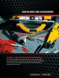
Hercu-Link Air <strong>BOP</strong> <strong>Handling</strong> <strong>Systems</strong>DIMENSIONS AND DRAWINGS of Piston Motor Drive – 20 to 200 tons Lifting CapacityDimensions (millimeters)Model No. A B C D E F G H J K L M N O P Q R S T W X Y ZBHS20M 813 672 98 - 197 66 483 378 1149 197 127 152 216 256 64 156 184 67 49 503 222 221 -BHS30M 895 749 114 - 229 76 483 378 1251 197 127 133 254 273 86 175 219 83 65 508 200 279 -BHS40M-4 903 864 149 - 298 92 540 425 1300 197 127 240 216 310 102 229 289 78 56 495 83 346 -Dimensions (inches)Model No. A B C D E F G H J K L M N O P Q R S T W X Y ZBHS20M 32 26.44 3.88 - 7.75 2.59 19 14.88 45.25 7.75 5 6 8.5 10.06 2.5 6.13 7.25 2.63 1.94 19.81 8.75 8.69 -BHS30M 35.25 29.5 4.5 - 9 3 19 14.88 49.25 7.75 5 5.25 10 10.75 3.38 6.88 8.63 3.25 2.56 20 7.88 11 -BHS40M-4 35.56 34 5.88 - 11.75 3.63 21.25 16.75 51.19 7.75 5 9.44 8.5 12.06 4 9 11.38 3.06 2.19 19.5 3.25 13.63 -Chain Container Dimensions for 9m (30 ft) standard lift (1) – millimeters (inches)Model No. U1 U2 U3BHS20M 658 (25.9) 620 (24.4) 483 (19.0)BHS30M 787 (31.0) 630 (24.8) 483 (19.0)BHS40M-4 749 (29.5) 706 (27.8) 533 (21.0)(1) Chain containers are available with many other dimensions. Please contact Client Services for details.BHS20M, BHS30M, and BHS40M-4 series (4-wheel trolley models)XBHercu-Link Dimensions and DrawingsWU2CENPOAJLGSTHAir Inlet (3/4" ID NPT)Q RKFU1YMU3Notes:Dimensions are approximate and subject to change, please contact factory for certified prints.Allow ± 2% on all dimensions.Trailing trolley required to support chain container with 10.7m (35.1 ft) of lift or more. Standard on BHS30M.12
Hercu-Link Air <strong>BOP</strong> <strong>Handling</strong> <strong>Systems</strong>DIMENSIONS AND DRAWINGS of Piston Motor Drive – 20 to 200 tons Lifting CapacityDimensions (millimeters)Model No. A B C D E F G H J K L M N O P Q R S T W X Y ZBHS40M-8 903 1454 406 616 229 92 540 425 1286 197 127 240 216 291 102 175 219 81 65 438 - 346 584BHS50M 1040 1568 578 616 229 92 495 362 1422 245 251 175 286 291 102 175 219 81 65 484 - 346 699BHS75M 1243 1648 610 673 298 129 572 438 1702 245 251 283 286 330 121 229 289 78 57 487 - 392 622BHS100M 1346 1648 610 673 298 165 572 438 1842 245 251 321 286 330 165 229 289 78 57 487 - 622 622Dimensions (inches)Model No. A B C D E F G H J K L M N O P Q R S T W X Y ZBHS40M-8 35.56 57.25 16 24.25 9 3.63 21.25 16.75 50.63 7.75 5 9.44 8.5 11.44 4 6.88 8.63 3.19 2.56 17.25 - 13.63 23BHS50M 40.94 61.75 22.75 24.25 9 3.63 19.5 14.25 56 9.63 9.88 6.88 11.25 11.44 4 6.88 8.63 3.19 2.56 19.06 - 13.63 27.5BHS75M 48.94 64.88 24 26.5 11.75 5.06 22.5 17.25 67 9.63 9.88 11.13 11.25 13 4.75 9 11.38 3.06 2.25 19.19 - 15.44 24.5BHS100M 53 64.88 24 26.5 11.75 6.5 22.5 17.25 72.5 9.63 9.88 12.63 11.25 13 6.5 9 11.38 3.06 2.25 19.19 - 20.63 24.5Chain Container Dimensions for 9m (30 ft) standard lift (1) – millimeters (inches)Model No. U1 U2 U3BHS40M-8 749 (29.5) 706 (27.8) 533 (21.0)BHS50M 795 (31.3) 706 (27.8) 533 (21.0)BHS75M 886 (34.9) 859 (33.8) 610 (24.0)BHS100M 922 (36.3) 935 (36.8) 635 (25.0)(1) Chain containers are available with many other dimensions. Please contact Client Services for details.BHS40M-8, BHS50M, BHS75M, and BHS100M series (8-wheel trolley models)BCDZEOWJNAir Inlet(1" ID NPT,exceptBHS40M-8is 3/4" ID NPT)ALGHSTMQRKHercu-Link Dimensions and DrawingsU2PFU1YU3*Notes:Dimensions are approximate and subject to change, please contact factory for certified prints.Allow ± 2% on all dimensions.( * ) Contact Client Services for specifications.13
Liftchain Air and Hydraulic <strong>BOP</strong> <strong>Handling</strong> <strong>Systems</strong>DIMENSIONS AND DRAWINGS – 25 to 200 tons Lifting CapacityLiftchain Dimensions and DrawingsDimensions (millimeters)Model No. A B C D E F G H I J K L MLCA Air SeriesBS25LCA2P 1128 500 120 - 240 67 318 253 338 1415 228 85 150BS30LCA3P 1242 642 156 - 312 80 377 311 342 1592 228 85 200BS36LCA3P 1242 642 156 - 312 80 377 311 342 1592 228 85 200BS50LCA4P 1290 642 156 - 312 94 377 311 342 1606 228 85 200LCH Hydraulic SeriesBS25LCH2P 1128 500 120 - 240 67 318 253 357 1415 228 143 150BS30LCH3P 1242 642 156 - 312 80 377 311 360 1592 228 143 200BS36LCH3P 1242 642 156 - 312 80 377 311 360 1592 228 143 200BS50LCH4P 1290 642 156 - 312 94 377 311 360 1606 228 143 200Dimensions (millimeters)Model No. N O P Q R S T U V W X Y ZLCA Air SeriesBS25LCA2P 203 220 58 160 200 48 68 - 58 739 - 222 -BS30LCA3P 206 270 78 225 272 56 80 - 58 797 - 283 -BS36LCA3P 206 270 78 225 272 56 80 - 58 797 - 283 -BS50LCA4P 235 270 87 225 272 56 80 - 58 797 - 339 -LCH Hydraulic SeriesBS2 5LCH2P 203 220 58 160 200 48 68 - 58 739 - 222 -BS30LCH3P 206 270 78 225 272 56 80 - 58 797 - 283 -BS36LCH3P 206 270 78 225 272 56 80 - 58 797 - 283 -BS50LCH4P 235 270 87 225 272 56 80 - 58 797 - 339 -Dimensions (inches)Model No. A B C D E F G H I J K L MLCA Air SeriesBS25LCA2P 44.41 19.68 4.72 - 9.45 2.64 12.52 9.96 13.3 55.7 8.98 3.35 5.9BS30LCA3P 48.9 25.27 6.14 - 12.28 3.15 14.84 12.24 13.46 62.68 8.98 3.35 7.87BS36LCA3P 48.9 25.27 6.14 - 12.28 3.15 14.84 12.24 13.46 62.68 8.98 3.35 7.87BS50LCA4P 50.79 25.27 6.14 - 12.28 3.7 14.84 12.24 13.46 63.23 8.98 3.35 7.87LCH Hydraulic SeriesBS25LCH2P 44.41 19.68 4.72 - 9.45 2.64 12.52 9.96 14.05 55.7 8.98 5.63 5.9BS30LCH3P 48.9 25.27 6.14 - 12.28 3.15 14.84 12.24 14.17 62.68 8.98 5.63 7.87BS36LCH3P 48.9 25.27 6.14 - 12.28 3.15 14.84 12.24 14.17 62.68 8.98 5.63 7.87BS50LCH4P 50.79 25.27 6.14 - 12.28 3.7 14.84 12.24 14.17 63.23 8.98 5.63 7.87Dimensions (inches)Model No. N O P Q R S T U V W X Y ZLCA Air SeriesBS25LCA2P 7.99 8.66 2.28 6.3 7.87 1.89 2.68 - 2.28 29.09 - 8.74 -BS30LCA3P 8.11 10.63 3.07 8.86 10.71 2.2 3.15 - 2.28 31.38 - 11.14 -BS36LCA3P 8.11 10.63 3.07 8.86 10.71 2.2 3.15 - 2.28 31.38 - 11.14 -BS50LCA4P 9.25 10.63 3.42 8.86 10.71 2.2 3.15 - 2.28 31.38 - 13.35 -LCH Hydraulic SeriesBS25LCH2P 7.99 8.66 2.28 6.3 7.87 1.89 2.68 - 2.28 29.09 - 8.74 -BS30LCH3P 8.11 10.63 3.07 8.86 10.71 2.2 3.15 - 2.28 31.38 - 11.14 -BS36LCH3P 8.11 10.63 3.07 8.86 10.71 2.2 3.15 - 2.28 31.38 - 11.14 -BS50LCH4P 9.25 10.63 3.42 8.86 10.71 2.2 3.15 - 2.28 31.38 - 13.35 -14
STOPLiftchain Air and Hydraulic <strong>BOP</strong> <strong>Handling</strong> <strong>Systems</strong>DIMENSIONS AND DRAWINGS – 25 to 200 tons Lifting CapacityChain Container Dimensions for 9m (30 ft) standard lift (1) – millimeters (inches)Model No. U1 U2 U3BS25LC_2P 565 (22.24) 720 (28.35) 400 (15.75)BS30LC_3P 565 (22.24) 720 (28.35) 400 (15.75)BS36LC_3P 565 (22.24) 720 (28.35) 400 (15.75)BS50LC_4P 565 (22.24) 720 (28.35) 550 (21.65)(1) Chain containers are available with many other dimensions. Please contact Client Services for details.BS25LC_2 - BS30LC_3 - BS36LC_3 - BS50LC_4 seriesBEIVCVT SQRU2 WNPAJKHGLYFOMAir inlet 3/4" ID BSPLiftchain Dimensions and DrawingsU1U3*4 leversremote controlNotes:Dimensions are approximate and subject to change, please contact factory for certified prints.Allow ± 2% on all dimensions.( * ) Contact Client Services for specifications.15
Liftchain Air and Hydraulic <strong>BOP</strong> <strong>Handling</strong> <strong>Systems</strong>DIMENSIONS AND DRAWINGS – 25 to 200 tons Lifting CapacityDimensions (millimeters)Model No. A B C D E F G H I J K L MLiftchain Air SeriesBS50LCA2P 976 1240 370 500 240 97 492 367 342 1293 223 196 190BS75LCA3P 1170 1552 455 642 312 132 547 472 360 1572 223 196 278BS100LCA4P 1392 1552 455 642 312 152 547 472 360 1662 223 196 281Liftchain Hydraulic SeriesBS50LCH2P 976 1240 370 500 240 97 446 265 357 1293 298 137 190BS75LCH3P 1170 1552 455 642 312 132 500 372 360 1572 298 137 278BS100LCH4P 1392 1552 455 642 312 152 500 372 360 1662 298 137 281Dimensions (millimeters)Model No. N O P Q R S T U V W X Y ZLiftchain Air SeriesBS50LCA2P 276 220 82 160 200 48 68 - 58 436 - 339 500BS75LCA3P 298 270 103 225 272 56 80 - 58 494 - 384 598BS100LCA4P 352 270 118 225 272 56 80 - 58 494 - 384 598Liftchain Hydraulic SeriesBS50LCH2P 276 220 82 160 200 48 68 - 58 436 - 339 500BS75LCH3P 298 270 103 225 272 56 80 - 58 494 - 384 598BS100LCH4P 352 270 118 225 272 56 80 - 58 494 - 384 598Liftchain Dimensions and DrawingsDimensions (inches)Model No. A B C D E F G H I J K L MLiftchain Air SeriesBS50LCA2P 38.42 48.82 14.57 19.68 9.45 3.82 19.37 14.45 13.46 50.9 8.78 7.72 7.48BS75LCA3P 46.06 61.1 17.91 25.28 12.28 5.2 21.5 18.58 14.17 61.89 8.78 7.72 10.94BS100LCA4P 54.8 61.1 17.91 25.28 12.28 5.98 21.5 18.58 14.17 65.43 8.78 7.72 11.06Liftchain Hydraulic SeriesBS50LCH2P 38.42 48.82 14.57 19.68 9.45 3.82 17.56 10.43 14.05 50.9 11.73 5.39 7.48BS75LCH3P 46.06 61.1 17.91 25.28 12.28 5.2 19.68 14.64 14.17 61.89 11.73 5.39 10.94BS100LCH4P 54.8 61.1 17.91 25.28 12.28 5.98 19.68 14.64 14.17 65.43 11.73 5.39 11.06Dimensions (inches)Model No. N O P Q R S T U V W X Y ZLiftchain Air SeriesBS50LCA2P 10.87 8.66 3.23 6.3 7.87 1.89 2.68 - 2.28 17.16 - 13.35 19.68BS75LCA3P 11.73 10.63 4.05 8.86 10.71 2.2 3.15 - 2.28 19.45 - 15.12 23.54BS100LCA4P 11.73 10.63 4.65 8.86 10.71 2.2 3.15 - 2.28 19.45 - 15.12 23.54Liftchain Hydraulic SeriesBS50LCH2P 10.87 8.66 3.23 6.3 7.87 1.89 2.68 - 2.28 17.16 - 13.35 19.68BS75LCH3P 11.73 10.63 4.05 8.86 10.71 2.2 3.15 - 2.28 19.45 - 15.12 23.54BS100LCH4P 11.73 10.63 4.65 8.86 10.71 2.2 3.15 - 2.28 19.45 - 15.12 23.5416
LSTOPLiftchain Air and Hydraulic <strong>BOP</strong> <strong>Handling</strong> <strong>Systems</strong>DIMENSIONS AND DRAWINGS – 25 to 200 tons Lifting CapacityChain Container Dimensions for 9m (30 ft) standard lift (1) – millimeters (inches)Model No. U1 U2 U3BS50LC_2P 850 (33.46) 840 (33.07) 800 (31.50)BS75LC_3P 955 (37.60) 1055 (41.54) 800 (31.50)BS100LC_4P 955 (37.60) 1055 (41.54) 800 (31.50)(1) Chain containers are available with many other dimensions. Please contact Client Services for details.BS50LC_2 - BS75LC_3 - BS100LC_4 seriesBGITSHVAir InletCZDEVMJ37,5TU3U1YPFAKWQRO*U2N4 leversremote controlLiftchain Dimensions and DrawingsNotes:Dimensions are approximate and subject to change, please contact factory for certified prints.Allow ± 2% on all dimensions.( * ) Contact Client Services for specifications.17
STOPLiftchain Air and Hydraulic <strong>BOP</strong> <strong>Handling</strong> <strong>Systems</strong>DIMENSIONS AND DRAWINGS – 25 to 200 tons Lifting CapacityDimensions – millimeters (inches)Model No. A B C D E F G H I J K L MLiftchain Air SeriesBS150LCA3P 1845 (73) 3254 (128) 906 (36) 642 (25) 312 (12) 190 (7) 714 (28) 714 (28) 360 (14) 2305 (91) 298 (12) 196 (8) 490 (19)BS200LCA4P 1901 (75) 3254 (128) 906 (36) 642 (25) 312 (12) 212 (8) 714 (28) 714 (28) 360 (14) 2383 (94) 298 (12) 196 (8) 430 (17)Liftchain Hydraulic SeriesBS150LCH3P 1845 (73) 3254 (128) 906 (36) 642 (25) 312 (12) 190 (7) 528 (21) 684 (27) 360 (14) 2305 (91) 298 (12) 199 (8) 490 (20)BS200LCH4P 1901 (75) 3254 (128) 906 (36) 642 (25) 312 (12) 212 (8) 528 (21) 684 (27) 360 (14) 2383 (94) 298 (12) 199 (8) 430 (17)Dimensions – millimeters (inches)Model No. N O P Q R S T U V W X Y ZLiftchain Air SeriesBS150LCA3P 420 (17) 270 (11) 152 (6) 225 (9) 272 (11) 56 (2) 80 (3) - 58 (2) 790 (31) - 574 (23) 700 (28)BS200LCA4P 490 (19) 270 (11) 180 (7) 225 (9) 272 (11) 56 (2) 80 (3) - 58 (2) 790 (31) - 606 (24) 700 (28)Liftchain Hydraulic SeriesBS150LCH3P 420 (17) 270 (11) 152 (6) 225 (9) 272 (11) 56 (2) 80 (3) - 58 (2) 790 (31) 488 (19) 574 (23) 700 (28)BS200LCH4P 490 (19) 270 (11) 180 (7) 225 (9) 272 (11) 56 (2) 80 (3) - 58 (2) 790 (31) 488 (19) 606 (24) 700 (28)Chain Container Dimensions for 9m (30 ft) standard lift (1) – millimeters (inches)Model No. U1 U2 U3BS150LC_3P 1200 (47.24) 1200 (47.24) 920 (36.22)BS200LC_4P 1200 (47.24) 1200 (47.24) 920 (36.22)(1) Chain containers are available with many other dimensions. Please contact Client Services for details.BS150LC_3 - BS200LC_4 seriesLiftchain Dimensions and DrawingsVU2WOCBE XE ZEX ENPD4 leversremote controlAAir inlet 3/4" ID BSPJVRKHITNFQSGILYU1U3Notes:Dimensions are approximate and subject to change, please contact factory for certified prints.Allow ± 2% on all dimensions.( * ) Contact Client Services for specifications.*18
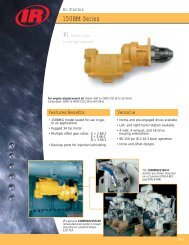
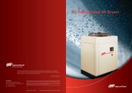
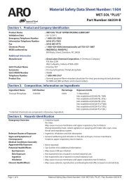
<strong>BOP</strong> <strong>Handling</strong> <strong>Systems</strong>ENGINEERED SOLUTIONSFor further information, technical support, or a quotation on one of our engineered <strong>BOP</strong> handling systems,please contact Client Services.BHS150M and BHS200M seriesOPTIONAL CHAINBUCKET*ULBS100LCA4 series (Ultra-low headroom design)Air inlet2x 1"1/4 ID BSPChaincontainerEngineered Solutions19
Contact InformationWORLDWIDE LOCATIONSOffice and distributors in principal cities throughout the world. Contact the nearest <strong>Ingersoll</strong> <strong>Rand</strong> office for the name and addressof the distributor in your country or write to: <strong>Ingersoll</strong> <strong>Rand</strong>, 2724 6th Avenue South, Seattle, WA 98134-0046 USA.United States OfficesFor Order Entry and Order Status:<strong>Ingersoll</strong> <strong>Rand</strong> Distribution Center510 Hester Drive, P.O. Box 618, White House, TN 37188Phone: (866) 207-6923 Fax: (615) 285-0802For Technical Support:Client Services2724 Sixth Avenue South, Seattle, WA 98134Phone: (206) 624-0466 Fax: (206) 624-6265Toll free: (866) 273-3278E-mail: WinchandHoistSolutions@irco.comCanadaNational Sales OfficeToronto, Ontario51 Worcester Road, Rexdale, Ontario M9W 4K2Phone: (877) 924-7435 Fax: (416) 213-4510Order Desk: (877) 924-7435 Fax: (416) 213-4506Mexico<strong>Ingersoll</strong> <strong>Rand</strong> S.A. de C.V.Boulevard Centro Industrial No.11Industrial Puente de Vigas54070 Tlalnepantla, Estado de MéxicoPhone: 52 (55) 85 03 66 00 Fax: 52 (55) 55 65 30 72Ext. 6627 & 6628E-mail: mexicot&h@irco.comInternationalBrazilAlameda Caiapós 311Tamboré - Barueri - São Paulo - Brazil 06460-110Phone: 55-11-2109 . 8950 Fax: 55-11-2109 . 8998Europe, Middle East and Africa<strong>Ingersoll</strong> <strong>Rand</strong> Material <strong>Handling</strong> – Douai Operations529, avenue Roger Salengro, 59450 SIN LE NOBLE, FrancePhone: (33) 3-27-93-08-08 Fax: (33) 3-27-93-08-19E-mail: dou_irep@eu.irco.com<strong>Ingersoll</strong> <strong>Rand</strong> SEA Pte. Ltd.42 Benoi Road, Jurong 629903, SingaporePhone: 65-6861-1555 Fax: 65-6862-1373China <strong>Ingersoll</strong> <strong>Rand</strong> Co.7F, Xuhui Yuan Building1089 Zhong Shan Nan 2 Road, Shanghai 200030, ChinaPhone: 86-21-5452 9898 Fax: 86-21-54101110<strong>Ingersoll</strong> <strong>Rand</strong> India<strong>Ingersoll</strong> <strong>Rand</strong> Wadco Tools Ltd.19, Chetak Apartments, Sheth Motisha Lane (Love Lane)Mazagon, Mumbai 40010 IndiaPhone: 91-120-48955116 (-126) Fax: 91-120-4895127Call 1-800-IR HOIST (474-6478) for thedistributor nearest you.Visit our web site at:www.irtools.comWARNING: This equipment is not designed for transporting people orlifting loads over people. It is the user’s responsibility to determine thesuitability of this product for any particular use and to check compliancewith applicable regulations. Before installation, see maintenance andoperations manual for additional warnings and precautions.© 2008 <strong>Ingersoll</strong> <strong>Rand</strong> Company Limited Form No. MHD55148/050508/Printed in U.S.A.