R-410A
R-410A
R-410A
- No tags were found...

Create successful ePaper yourself
Turn your PDF publications into a flip-book with our unique Google optimized e-Paper software.
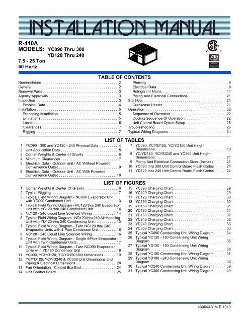
R-<strong>410A</strong>MODELS: YC090 Thru 300YD120 Thru 2407.5 - 25 Ton60 HertzNomenclature . . . . . . . . . . . . . . . . . . . . . . . . . . . . . . . . . . . . . 2General . . . . . . . . . . . . . . . . . . . . . . . . . . . . . . . . . . . . . . . . . . 2Renewal Parts . . . . . . . . . . . . . . . . . . . . . . . . . . . . . . . . . . . . . 3Agency Approvals . . . . . . . . . . . . . . . . . . . . . . . . . . . . . . . . . . 3Inspection . . . . . . . . . . . . . . . . . . . . . . . . . . . . . . . . . . . . . . . . 3Physical Data . . . . . . . . . . . . . . . . . . . . . . . . . . . . . . . . . . . 4Installation . . . . . . . . . . . . . . . . . . . . . . . . . . . . . . . . . . . . . . . . 5Preceding Installation . . . . . . . . . . . . . . . . . . . . . . . . . . . . . 5Limitations . . . . . . . . . . . . . . . . . . . . . . . . . . . . . . . . . . . . . . 5Location. . . . . . . . . . . . . . . . . . . . . . . . . . . . . . . . . . . . . . . . 5Clearances . . . . . . . . . . . . . . . . . . . . . . . . . . . . . . . . . . . . . 7Rigging . . . . . . . . . . . . . . . . . . . . . . . . . . . . . . . . . . . . . . . . 71 YC090 - 300 and YD120 - 240 Physical Data . . . . . . . . . 42 Unit Application Data . . . . . . . . . . . . . . . . . . . . . . . . . . . . 53 Corner Weights & Center of Gravity . . . . . . . . . . . . . . . . 64 Minimum Clearances . . . . . . . . . . . . . . . . . . . . . . . . . . . . 75 Electrical Data - Outdoor Unit - AC Without PoweredConvenience Outlet . . . . . . . . . . . . . . . . . . . . . . . . . . . . . 96 Electrical Data - Outdoor Unit - AC With PoweredConvenience Outlet . . . . . . . . . . . . . . . . . . . . . . . . . . . . 101 Corner Weights & Center Of Gravity . . . . . . . . . . . . . . . . 62 Typical Rigging . . . . . . . . . . . . . . . . . . . . . . . . . . . . . . . . 73 Typical Field Wiring Diagram - NC090 Evaporator Unitwith YC090 Condenser Unit . . . . . . . . . . . . . . . . . . . . . . 134 Typical Field Wiring Diagram - NC120 thru 240 EvaporatorUnit with YC120 thru 240 Condenser Unit . . . . . . . . . . . 145 NC120 - 240 Liquid Line Solenoid Wiring . . . . . . . . . . . 146 Typical Field Wiring Diagram - ND120 thru 240 Air HandlingUnit with YD120 thru 240 Condensing Unit . . . . . . . . . . 157 Typical Field Wiring Diagram - Twin NC120 thru 240Evaporator Units with 4-Pipe Condenser Unit . . . . . . . . 168 NC120 - 240 Liquid Line Solenoid Wiring . . . . . . . . . . . 169 Typical Field Wiring Diagram - Single 4-Pipe EvaporatorUnit with Twin Condenser Units . . . . . . . . . . . . . . . . . . . 1710 Typical Field Wiring Diagram - Twin NC090 EvaporatorUnits with YD180 Condenser Unit . . . . . . . . . . . . . . . . . 1811 YC090, YC/YD120, YC/YD150 Unit Dimensions . . . . . . 1912 YC/YD180, YC/YD240 & YC300 Unit Dimensions andPiping & Electrical Dimensions . . . . . . . . . . . . . . . . . . . 2013 Fan Orientation - Control Box End . . . . . . . . . . . . . . . . . 2414 Unit Control Board . . . . . . . . . . . . . . . . . . . . . . . . . . . . . 25TABLE OF CONTENTSLIST OF TABLESLIST OF FIGURESPhasing . . . . . . . . . . . . . . . . . . . . . . . . . . . . . . . . . . . . . . . . 8Electrical Data. . . . . . . . . . . . . . . . . . . . . . . . . . . . . . . . . . . 9Refrigerant Mains . . . . . . . . . . . . . . . . . . . . . . . . . . . . . . . 11Piping And Electrical Connections . . . . . . . . . . . . . . . . . . 21Start-Up . . . . . . . . . . . . . . . . . . . . . . . . . . . . . . . . . . . . . . . . . 21Crankcase Heater . . . . . . . . . . . . . . . . . . . . . . . . . . . . . . . 21Operation . . . . . . . . . . . . . . . . . . . . . . . . . . . . . . . . . . . . . . . 22Sequence of Operation . . . . . . . . . . . . . . . . . . . . . . . . . . . 22Cooling Sequence Of Operation . . . . . . . . . . . . . . . . . . . . 22Unit Control Board Option Setup. . . . . . . . . . . . . . . . . . . . 25Troubleshooting . . . . . . . . . . . . . . . . . . . . . . . . . . . . . . . . . . 26Typical Wiring Diagrams . . . . . . . . . . . . . . . . . . . . . . . . . . . . 347 YC090, YC/YD120, YC/YD150 Unit HeightDimensions . . . . . . . . . . . . . . . . . . . . . . . . . . . . . . . . . . 198 YC/YD180, YC/YD240 and YC300 Unit HeightDimensions . . . . . . . . . . . . . . . . . . . . . . . . . . . . . . . . . . 219 Piping And Electrical Connection Sizes (Inches) . . . . . . 2110 YC090 thru 300 Unit Control Board Flash Codes . . . . . 2411 YD120 thru 240 Unit Control Board Flash Codes . . . . . 2415 YC090 Charging Chart . . . . . . . . . . . . . . . . . . . . . . . . . . 2916 YC120 Charging Chart . . . . . . . . . . . . . . . . . . . . . . . . . . 2917 YD120 Charging Chart . . . . . . . . . . . . . . . . . . . . . . . . . . 3018 YC150 Charging Chart . . . . . . . . . . . . . . . . . . . . . . . . . . 3019 YD150 Charging Chart . . . . . . . . . . . . . . . . . . . . . . . . . . 3120 YC180 Charging Chart . . . . . . . . . . . . . . . . . . . . . . . . . . 3121 YD180 Charging Chart . . . . . . . . . . . . . . . . . . . . . . . . . . 3222 YC240 Charging Chart . . . . . . . . . . . . . . . . . . . . . . . . . . 3223 YD240 Charging Chart . . . . . . . . . . . . . . . . . . . . . . . . . . 3324 YC300 Charging Chart . . . . . . . . . . . . . . . . . . . . . . . . . . 3325 Typical YC090 Condensing Unit Wiring Diagram . . . . . 3426 Typical YC120 - 150 Condensing Unit WiringDiagram . . . . . . . . . . . . . . . . . . . . . . . . . . . . . . . . . . . . . 3527 Typical YD120 - 150 Condensing Unit WiringDiagram . . . . . . . . . . . . . . . . . . . . . . . . . . . . . . . . . . . . . 3628 Typical YC180 Condensing Unit Wiring Diagram . . . . . 3729 Typical YD180 - 240 Condensing Unit WiringDiagram . . . . . . . . . . . . . . . . . . . . . . . . . . . . . . . . . . . . . 3830 Typical YC240 Condensing Unit Wiring Diagram . . . . . 3931 Typical YC300 Condensing Unit Wiring Diagram . . . . . 40430643-YIM-E-1010
430643-YIM-E-1010Safety ConsiderationsInstaller should pay particular attention to the words: NOTE,CAUTION, and WARNING. Notes are intended to clarify ormake the installation easier. Cautions are given to preventequipment damage. Warnings are given to alert installer thatpersonal injury and/or equipment damage may result ifinstallation procedure is not handled properly.ReferenceThis instruction covers the installation and operation of thebasic condensing unit. For refrigerant piping installationinstructions refer to document 247077 “Application Data -General Piping Recommendations for Split System AirConditioning and Heat Pumps”. For information on theinstallation and operation of the evaporator blower units, referto Instruction Manual No. 508526.All accessories come with a separate Installation Manual.Improper installation may create a condition where theoperation of the product could cause personal injury orproperty damage. Improper installation, adjustment,alteration, service or maintenance can cause injury orproperty damage. Refer to this manual for assistance orfor additional information, consult a qualified contractor,installer or service agency.Renewal PartsContact your local Source 1 Distribution Center for authorizedreplacement parts.Agency ApprovalsDesign certified by CSA as follows:1. For use as a cooling unit.2. For outdoor installation only.Before performing service or maintenance operations onunit, turn off main power switch to unit. Electrical shockcould cause personal injury. Improper installation,adjustment, alteration, service or maintenance cancause injury or property damage. Refer to this manual.For assistance or additional information consult aqualified installer, service agency or the gas supplier.InspectionAs soon as a unit is received, it should be inspected for possibledamage during transit. If damage is evident, the extent of thedamage should be noted on the carrier’s freight bill. A separaterequest for inspection by the carrier’s agent should be made inwriting.This system uses R-<strong>410A</strong> Refrigerant which operates athigher pressures than R-22. No other refrigerant may beused in this system. Gage sets, hoses, refrigerantcontainers and recovery systems must be designed tohandle R-<strong>410A</strong>. If you are unsure, consult theequipment manufacturer. Failure to use R-<strong>410A</strong>compatible servicing equipment may result in propertydamage or injury.This product must be installed in strict compliance withthe enclosed installation instructions and any applicablelocal, state and national codes including, but not limitedto, building, electrical, and mechanical codes.Johnson Controls Unitary Products 3
430643-YIM-E-1010Physical DataTable 1:YC090 - 300 and YD120 - 240 Physical DataComponentModelsYC090 YC120 YD120 YC150 YD150 YC180 YD180 YC240 YD240 YC300Nominal Tonnage 7.5 10 10 12.5 12.5 15 15 20 20 25REFRIGERANTRefrigerant type R-<strong>410A</strong> R-<strong>410A</strong> R-<strong>410A</strong> R-<strong>410A</strong> R-<strong>410A</strong> R-<strong>410A</strong> R-<strong>410A</strong> R-<strong>410A</strong> R-<strong>410A</strong> R-<strong>410A</strong>Holding charge (lb) 11.0 1.0 1.0 1.0 1.0 1.0 1.0 1.0 1.0 1.0Operating Charge (lb) 2 System #1 14.0 18.0 9.9 24.0 11.5 27.0 13.5 33.5 18.8 35System #2 --- --- 9.9 --- 11.5 --- 13.5 --- 18.8 ---DIMENSIONS (inches)Length 59.1 59.1 59.1 59.1 59.1 59.1 59.1 59.1 59.1 59.1Width 31.9 31.9 31.9 31.9 31.9 64.1 64.1 64.1 64.1 64.1Height 44.5 50.0 50.0 50.0 50.0 44.5 44.5 50.0 50.0 50.0WEIGHTS (lb)Shipping 390 499 493 499 493 914 899 945 930 945Operating 387 497 490 497 490 909 894 942 927 942COMPRESSORS 3Single Tandem Single Tandem Single Tandem Single Tandem Single TandemTypeScroll Scroll Scroll Scroll Scroll Scroll Scroll Scroll Scroll ScrollQuantity 1 1 2 1 2 1 2 1 2 1Nominal Capacity (Tons)System #1 7.5 10 5 12.5 6.3 15 7.5 20 10 25System #2 --- --- 5 --- 6.3 --- 7.5 --- 10 ---Capacity StagesSystem #1 1 2 1 2 1 2 1 2 1 2System #2 --- --- 1 --- 1 --- 1 --- 1 ---SYSTEM DATANo. Refrigeration Circuits 1 1 2 1 2 1 2 1 2 1Suction Line OD (in.) 1 1/8 1 3/8 1 1/8 1 3/8 1 1/8 1 5/8 1 3/8 1 5/8 1 3/8 1 5/8Liquid Line OD (in.) 5/8 7/8 5/8 7/8 5/8 7/8 5/8 7/8 5/8 7/8OUTDOOR COIL DATAFace area (Sq. Ft.) 23.8 29.0 29.0 29.0 29.0 47.5 47.5 58.1 58.1 58.1Rows 1 1 1 1 1 1 1 1 1 1Fins per inch 23 23 23 23 23 23 23 23 23 23Tube diameter (in./MM) 0.71 / 18 0.71 / 18 0.71 / 18 0.71 / 18 0.71 / 18 0.71 / 18 0.71 / 18 0.71 / 18 0.71 / 18 0.71 / 18Circuitry Type 2-pass 2-pass 2-pass 2-pass 2-pass 2-pass 2-pass 2-pass 2-pass 2-passRefrigerant Control --- --- --- --- --- --- --- --- --- ---CONDENSER FAN DATANo. Fans / Diameter (in.) 2/24 2/24 2/24 2/24 2/24 4/24 4/24 4/24 4/24 4/24Type Axial Axial Axial Axial Axial Axial Axial Axial Axial AxialDrive type Direct Direct Direct Direct Direct Direct Direct Direct Direct DirectNo. speeds 1 1 1 1 1 1 1 1 1 1Number of motorsSystem #1 2 2 2 2 2 4 2 4 2 4System #2 --- --- --- --- --- --- 2 --- 2 ---Motor HP (ea.) 1/3 3/4 3/4 3/4 3/4 1/3 1/3 3/4 3/4 3/4Rotation 4CW CW CW CW CW CW CW CW CW CWRPM 850 1100 1100 1100 1100 850 850 1100 1100 1100Nominal CFMSystem #1 7500 9800 9800 9800 9800 15000 7500 19600 9800 19600System #2 --- --- --- --- --- --- 7500 --- 9800 ---1. Holding Charge is the amount in the unit as shipped from the factory.2. Includes matched indoor blower unit with 25 ft of piping.3. All compressors include crankcase heaters.4. When viewing the shaft end of the motor.4 Johnson Controls Unitary Products
430643-YIM-E-1010Table 2:InstallationPreceding InstallationIf a factory option convenience outlet is installed, theweatherproof outlet cover must be field installed. The covershall be located in the unit control box. To install the cover,remove the shipping label covering the convenience outlet,follow the instructions on the back of the weatherproof coverbox, and attach the cover to the unit using the (4) screwsprovided.LimitationsUnit Application DataVoltage Variation 1Min. / Max.Ambient Air on Condenser CoilMin. /Max.Suction Pressure at Compressor andCorresponding Temp. at SaturationMin. / Max.208/230-3-60 187/252460-3-60 432/504575-3-60 540/63040°F/125°F 2106.6 psig / 156.6 psig32.0 ºF / 55.0 ºF1.Utilization range “A” in accordance with ARI Standard 110.2.These units can operate in an ambient temperature of125°F providing the wet bulb temperature of the air enteringthe evaporator coil does not exceed 67°F. Unit canoperate to 0°F if equipped with a low ambient kit.208/230-3-60 and 380/415-3-50 units with factoryinstalled Powered Convenience Outlet Option are wiredfor 230v and 415v power supply respectively. Changetap on transformer for 208-3-60 or 380-3-50 operation.See unit wiring diagram.These units must be installed in accordance with all nationaland local safety codes. If no local codes apply, installation mustconform to the appropriate national codes. Units are designedto meet National Safety Code Standards. If components are tobe added to a unit to meet local codes, they are to be installedat the dealer's and/or the customer's expense.LocationUse the following guidelines to select a suitable location forboth the condensing unit and the evaporator.1. The condensing unit is designed for outdoor installationonly.2. The condenser fans are the propeller type and are notsuitable for use with ductwork in the condenser air stream.3. The condensing unit and the evaporator should bepositioned to minimize the number of bends in therefrigerant piping.4. The condensing unit should be as close to the evaporatoras practical.5. The condensing unit should not be installed where normaloperating sounds may be objectionable.6. The evaporator should be located within the building, eitheroutside or inside the conditioned space.Rooftop LocationsBe careful not to damage the roof. Consult the buildingcontractor or architect if the roof is bonded. Choose a locationwith adequate structural strength to support the unit.The condensing unit must be mounted on level supports. Thesupports can be channel iron beams or wooden beams treatedto reduce deterioration.Minimums of two (2) beams are required to support each unit.The beams should: (1) be positioned perpendicular to the roofjoists. (2) Extend beyond the dimensions of the section todistribute the load on the roof. (3) Be capable of adequatelysupporting the concentrated loads at the corners. These beamscan usually be set directly on the roof. Flashing is not required.NOTE: On bonded roofs, check for special installationrequirements.Ground Level LocationsIt is important that the units be installed on a substantial basethat will not settle, causing strain on the refrigerant lines andpossible leaks. A one-piece concrete slab with footers thatextend below the frost line is recommended. The slab shouldnot be tied to the building foundation, as noise will telegraphthrough the slab.Johnson Controls Unitary Products 5
430643-YIM-E-1010Table 3:Size(Tons)090(7.5)120(10)150(12.5)180(15)240(20)300(25)Corner Weights & Center of GravityModelWeight (lbs.) Center of Gravity (in.) 4 Point Load Location (lbs.)Shipping Operating X Y A B C DYC090 390 387 17 32.3 99 113 94 82YC120 499 497 17.3 32.3 124 147 122 103YD120 493 490 17.4 32.5 123 147 120 100YC150 499 497 17 32.3 127 145 120 105YD150 493 490 17.4 32.5 123 147 120 100YC180 914 909 32.5 31.5 239 246 215 209YD180 899 894 32.5 31.5 235 242 212 206YC240 945 942 30.3 31.0 261 234 212 236YD240 930 927 32.7 31.8 244 255 218 210YC300 945 942 30.3 31.0 261 234 212 236LEFTDALEFTDIM XDCGADIM XCGFRONTREARFRONTREARWIDTHCBWIDTHDIM YLENGTHRIGHTCBYC090, YC120, YD120,YC150, YD150DIM YLENGTHRIGHTYC180, YD180,YC240, YD240,YC300Figure 1:Corner Weights & Center Of GravityNOTE: Front of unit is considered the side having the unitcontrol box.Concrete piers can also support ground level units. These piersshould (1) extend below the frost line, (2) be located under eachof the section's four corners, and (3) be sized to carry the loadof the corner it supports.On either rooftop or ground level installations, rubber paddingcan be applied under the unit to lessen any transmission ofvibration.Holes are provided in the base rails for bolting the unit to itsfoundation.For ground level installations, precautions should be taken toprotect the unit from tampering and unauthorized persons frominjury. Screws on access panels will prevent casual tampering.Further safety precautions such as a fenced enclosure orlocking devices on the panels may be advisable. Check localauthorities for safety regulations.6 Johnson Controls Unitary Products
430643-YIM-E-1010ClearancesThe unit must be installed with sufficient clearance for air toenter the condenser coil, for air discharge and for servicingaccess. See Table 4 for clearances.NOTE: Additional clearance is required to remove thecompressors out the back of the unit, unless a means isavailable to lift the compressor out through the top ofthe unit.Table 4:Minimum ClearancesClearance DescriptionDistance in InchesOverhead (Top) 120Front 36Rear 36Left Side 30Right Side 30Bottom 10The unit may be moved or lifted with a forklift. Slotted openingsin the base rails are provided for this purpose.LENGTH OF FORKS MUST BE A MINIMUM OF 60 INCHES.Spreaders, longer than the largest dimension across theunit must be used across the top of the unit.Before lifting a unit, make sure that its weight isdistributed equally on the cables so that it will lift evenly.1.In all installations where snow accumulates and winter operationis expected, additional height must be provided toinsure normal condenser airflow.Do not permit overhanging structures or shrubs toobstruct condenser air discharge.RiggingExercise care when moving the unit. Do not remove anypackaging until the unit is near the place of installation. Rig theunit by attaching chain or cable slings to the lifting holesprovided in the base rails. Spreader bars, whose lengthexceeds the largest dimension across the unit, MUST be usedacross the top of the unit.Figure 2:Typical RiggingJohnson Controls Unitary Products 7
430643-YIM-E-1010Power WiringCheck the available power and the unit nameplate for correctvoltage. Run the necessary number of properly sized wires tothe unit. Provide a disconnect switch (if not included with theunit) and fusing as required (factory disconnect is a fuseddisconnect/breaker). Route the conduit through the largeknockout located on the front of the electrical box. See Table 5for Electrical Data.The disconnect switch may be bolted to the side of the unit butnot to any of the removable panels; this would interfere withaccess to the unit. Make sure that no refrigerant lines will bepunctured when mounting the disconnect switch, and note thatit must be suitable for outdoor installation.All power and control wiring must be in accordance withNational and Local electrical codes.Control WiringRoute the necessary low voltage control wires from theSimplicity control board to the thermostat and also from thelow voltage condenser unit control box to the terminal blockinside the evaporator unit. Refer to Figures 3 thru 10 for fieldwiring diagrams.Do not leave the system open to the atmosphere. Unitdamage could occur due to moisture being absorbed bythe POE oil in the system. This type of oil is highlysusceptible to moisture absorptionPOE (polyolester) compressor lubricants are known to causelong term damage to some synthetic roofing materials.Exposure, even if immediately cleaned up, may causeembrittlement (leading to cracking) to occur in one yearor more. When performing any service that may riskexposure of compressor oil to the roof, take precautionsto protect roofing.Procedures which risk oil leakage include, but are not limited to,compressor replacement, repairing refrigerant leaks, replacingrefrigerant components such as filter drier, pressure switch,metering device or coil.Units are shipped with compressor mountings which are factoryadjusted and ready for operation.CompressorsThe scroll compressors used in this product are specificallydesigned to operate with R-<strong>410A</strong> Refrigerant and cannot beinterchanged.Do not loosen compressor mounting bolts.PhasingThis system uses R-<strong>410A</strong> Refrigerant which operates athigher pressures than R-22. No other refrigerant may beused in this system.The compressor also uses a polyolester (POE oil), Mobil 3MAPOE. This oil is extremely hydroscopic, meaning it absorbswater readily. POE oil can absorb 15 times as much water asother oils designed for HCFC and CFC refrigerants. Take allnecessary precautions to avoid exposure of the oil to theatmosphere.Three-phase, scroll compressors operate in only one direction.If the scroll is drawing low amperage, has similar suction anddischarge pressures, or is producing a high noise level, thescroll is misphased. Change the incoming line connectionphasing to obtain the proper rotation.Scroll compressors require proper rotation to operateproperly. Failure to check and correct rotation may resultin property damage.8 Johnson Controls Unitary Products
430643-YIM-E-1010Electrical DataTable 5:ModelYC090YC120YD120YC150YD150YC180YD180YC240YD240YC300Electrical Data - Outdoor Unit - AC Without Powered Convenience OutletPowerSupplyCompressors Outdoor Fan Motor Pwr Conv Outlet MinimumRLA MCC LRA PowerFLACircuitQtyHP QtyFLA(each) (each) (each) Supply(each)Ampacity 1MaximumFuse Size(A) 2208/230-3-60 1 25.0 39 164 208/230-1-60 1/3 2 2.1 - 35.5 45460-3-60 1 12.2 19 100 460-1-60 1/3 2 1.2 - 17.6 25575-3-60 1 9.0 14 78 575-1-60 1/3 2 0.9 - 13.1 20208/230-3-60 2 18.1 28.3 137 208/230-1-60 3/4 2 3.0 - 46.8 60460-3-60 2 9.0 14.0 62 460-1-60 3/4 2 1.6 - 23.5 30575-3-60 2 6.8 10.6 50 575-1-60 3/4 2 1.4 - 18.0 20208/230-3-60 2 17.3 27 123 208/230-1-60 3/4 2 3.0 - 45.0 60460-3-60 2 9.6 15 70 460-1-60 3/4 2 1.6 - 24.8 30575-3-60 2 7.7 12 53 575-1-60 3/4 2 1.4 - 20.0 25208/230-3-60 2 22.4 35 149 208/230-1-60 3/4 2 3.0 - 56.5 70460-3-60 2 10.6 17 75 460-1-60 3/4 2 1.6 - 27.1 35575-3-60 2 7.7 12 54 575-1-60 3/4 2 1.4 - 20.0 25208/230-3-60 2 23.1 36 160 208/230-1-60 3/4 2 3.0 - 58.0 80460-3-60 2 12.2 19 87 460-1-60 3/4 2 1.6 - 30.7 40575-3-60 2 8.7 14 62 575-1-60 3/4 2 1.4 - 22.3 30208/230-3-60 2 25.0 39 164 208/230-1-60 1/3 4 2.1 - 64.7 80460-3-60 2 12.2 19 100 460-1-60 1/3 4 1.2 - 32.2 40575-3-60 2 9.0 14 78 575-1-60 1/3 4 0.9 - 24.0 30208/230-3-60 2 25.0 39 164 208/230-1-60 1/3 4 2.1 - 64.7 80460-3-60 2 12.2 19 100 460-1-60 1/3 4 1.2 - 32.2 40575-3-60 2 9.0 14 78 575-1-60 1/3 4 0.9 - 24.0 30208/230-3-60 2 30.1 47 225 208/230-1-60 3/4 4 3.0 - 79.8 100460-3-60 2 16.7 26 114 460-1-60 3/4 4 1.6 - 44.0 60575-3-60 2 12.2 19 80 575-1-60 3/4 4 1.4 - 32.9 45208/230-3-60 2 30.1 47 225 208/230-1-60 3/4 4 3.0 - 79.8 100460-3-60 2 16.7 26 114 460-1-60 3/4 4 1.6 - 44.0 60575-3-60 2 12.2 19 80 575-1-60 3/4 4 1.4 - 32.9 45208/230-3-60 2 48.1 75 245 208/230-1-60 3/4 4 3.0 - 120.3 150460-3-60 2 18.6 29 125 460-1-60 3/4 4 1.6 - 48.3 60575-3-60 2 14.7 23 100 575-1-60 3/4 4 1.4 - 38.5 501. Based on three, 75°C insulated copper conductors in conduit and ambient of 30°C.2. Maximum fuse or maximum circuit breaker (HACR type per NEC).Refer to NEC/NFPA No. 70, Articles 440-11, 12 for information on minimum disconnect sizing.Johnson Controls Unitary Products 9
430643-YIM-E-1010Table 6:ModelYC090YC120YD120YC150YD150YC180YD180YC240YD240YC300Electrical Data - Outdoor Unit - AC With Powered Convenience OutletPowerSupplyCompressors Outdoor Fan Motor Pwr Conv Outlet MinimumRLA MCC LRA PowerFLACircuitQtyHP QtyFLA(each) (each) (each) Supply(each)Ampacity 1MaximumFuse Size(A) 2208/230-3-60 1 25.0 39 164 208/230-1-60 1/3 2 2.1 10.0 45.5 60460-3-60 1 12.2 19 100 460-1-60 1/3 2 1.2 5.0 22.6 30575-3-60 1 9.0 14 78 575-1-60 1/3 2 0.9 4.0 17.1 25208/230-3-60 2 18.1 28.3 137 208/230-1-60 3/4 2 3.0 10.0 56.8 70460-3-60 2 9.0 14.0 62 460-1-60 3/4 2 1.6 5.0 28.5 35575-3-60 2 6.8 10.6 50 575-1-60 3/4 2 1.4 4.0 22.0 25208/230-3-60 2 17.3 27 123 208/230-1-60 3/4 2 3.0 10.0 55.0 70460-3-60 2 9.6 15 70 460-1-60 3/4 2 1.6 5.0 29.8 35575-3-60 2 7.7 12 53 575-1-60 3/4 2 1.4 4.0 24.0 30208/230-3-60 2 22.4 35 149 208/230-1-60 3/4 2 3.0 10.0 66.5 80460-3-60 2 10.6 17 75 460-1-60 3/4 2 1.6 5.0 32.1 40575-3-60 2 7.7 12 54 575-1-60 3/4 2 1.4 4.0 24.0 30208/230-3-60 2 23.1 36 160 208/230-1-60 3/4 2 3.0 10.0 68.0 90460-3-60 2 12.2 19 87 460-1-60 3/4 2 1.6 5.0 35.7 45575-3-60 2 8.7 14 62 575-1-60 3/4 2 1.4 4.0 26.3 30208/230-3-60 2 25.0 39 164 208/230-1-60 1/3 4 2.1 10.0 74.7 90460-3-60 2 12.2 19 100 460-1-60 1/3 4 1.2 5.0 37.2 45575-3-60 2 9.0 14 78 575-1-60 1/3 4 0.9 4.0 28.0 35208/230-3-60 2 25.0 39 164 208/230-1-60 1/3 4 2.1 10.0 74.7 90460-3-60 2 12.2 19 100 460-1-60 1/3 4 1.2 5.0 37.2 45575-3-60 2 9.0 14 78 575-1-60 1/3 4 0.9 4.0 28.0 35208/230-3-60 2 30.1 47 225 208/230-1-60 3/4 4 3.0 10.0 89.8 110460-3-60 2 16.7 26 114 460-1-60 3/4 4 1.6 5.0 49.0 60575-3-60 2 12.2 19 80 575-1-60 3/4 4 1.4 4.0 36.9 45208/230-3-60 2 30.1 47 225 208/230-1-60 3/4 4 3.0 10.0 89.8 110460-3-60 2 16.7 26 114 460-1-60 3/4 4 1.6 5.0 49.0 60575-3-60 2 12.2 19 80 575-1-60 3/4 4 1.4 4.0 36.9 45208/230-3-60 2 48.1 75 245 208/230-1-60 3/4 4 3.0 10.0 130.3 175460-3-60 2 18.6 29 125 460-1-60 3/4 4 1.6 5.0 53.3 70575-3-60 2 14.7 23 100 575-1-60 3/4 4 1.4 4.0 42.5 501. Based on three, 75°C insulated copper conductors in conduit and ambient of 30°C.2. Maximum fuse or maximum circuit breaker (HACR type per NEC).Refer to NEC/NFPA No. 70, Articles 440-11, 12 for information on minimum disconnect sizing.10 Johnson Controls Unitary Products
430643-YIM-E-1010Refrigerant MainsTake Adequate PrecautionsThis Split-System (Air Condensing / Heat Pump / AirHandling) unit is one component of an entire system. Assuch it requires specific application considerations withregard to the rest of the system (air handling unit, ductdesign, condensing unit, refrigerant piping and controlscheme).Failure to properly apply this equipment with the rest ofthe system may result in premature failure and/orreduced performance / increased costs. Warrantycoverage specifically excludes failures due to improperapplication and Unitary Products specifically disclaimsany liability resulting from improper application.Please refer to the equipment Technical Guide,Installation Manual and the piping applications bulletin247077 or call the applications department for UnitaryProducts @ 1-877-UPG-SERV for guidance.Line SizingWhen sizing refrigerant pipe for a split-system air conditioner,check the following:1. Suction line pressure drop due to friction.2. Liquid line pressure drop due to friction.3. Suction line velocity for oil return.4. Liquid line pressure drop due to vertical rise. For certainpiping arrangements, different sizes of suction line pipemay have to be used. The velocity of the refrigerant vapormust always be great enough to carry the oil back to thecompressor.5. Evaporator Located Below Condenser - On a splitsystem where the evaporator blower is located below thecondenser, the suction line must be sized for both pressuredrop and for oil return.6. Condenser Located Below Evaporator - When thecondenser is located below the evaporator blower, theliquid line must be designed for the pressure drop due toboth friction loss and vertical rise. If the pressure drop dueto vertical rise and friction exceeds 60 psi, some refrigerantwill flash before it reaches the thermal expansion valve.Flash gas:1. Increases the liquid line pressure loss due to friction that inturn causes further flashing.2. Reduces the capacity of the refrigerant control devicewhich starves the evaporator.3. Erodes the seat of the refrigerant control device.4. Causes erratic control of the refrigerant entering theevaporator.Many service problems can be avoided by taking adequateprecautions to provide an internally clean and dry system andby using procedures and materials that conform to establishedstandards.Use hard drawn copper tubing where no appreciable amount ofbending around pipes or other obstructions is necessary. If softcopper is used, care should be taken to avoid sharp bends thatmay cause a restriction. Pack fiberglass insulation and asealing material such as permagum around refrigerant lineswhere they penetrate a wall to reduce vibrations and to retainsome flexibility.Support all tubing at minimum intervals with suitable hangers,brackets or clamps.Braze all copper-to-copper joints with Silfos-5 or equivalentbrazing material. Do not use soft solder. Insulate all suctionlines with a minimum of 1/2" ARMAFLEX or equivalent thatmeets local codes. Liquid lines exposed to direct sunlight and/or high temperatures must also be insulated. Never soldersuction and liquid lines together. They can be taped together forconvenience and support purposes, but they must becompletely insulated from each other.The liquid and suction service ports on the condenser sectionpermit leak testing, evacuation, and partial charging of the fieldpiping and the evaporator without disturbing refrigerant storedin the condenser during initial installation.Before beginning installation of the main lines, be sure that theevaporator section has not developed a leak in transit. Checkpressure at the Schrader valve located on the header of eachcoil. If pressure still exists in the system, it can be assumed tobe leak free. If pressure DOES NOT exist the section will needto be repaired before evacuation and charging is performed.A filter-drier MUST be field-installed in the liquid line of everysystem to prevent dirt and moisture from damaging the system.Properly sized filter-driers are shipped with each condensingsection.NOTE: Installing a filter-drier does not eliminate the need forthe proper evacuation of a system before it is charged.A field-installed moisture indicating sight-glass should beinstalled in the liquid line(s) between the filter-drier and theevaporator coil. The moisture indicating sight-glass can be usedto check for excess moisture in the system.Both condenser and evaporator sections have copper sealingdisks brazed over the end of liquid and suction connections.The temperature required to make or break a brazed joint ishigh enough to cause oxidation of the copper unless an inertatmosphere is provided.NOTE: Dry nitrogen should flow through the system at all timeswhen heat is being applied and until the joint hasJohnson Controls Unitary Products 11
430643-YIM-E-1010cooled. The flow of nitrogen will prevent oxidation of thecopper lines during installation.Always punch a small hole in sealing disks before unbrazing toprevent the pressure in the line from blowing them off. Do notuse a drill as copper shavings can enter system.NOTE: Solenoid and hot gas bypass valves (if used) should beopened manually or electrically during brazing orevacuating.NOTE: Schrader valves located on unit service valves shouldhave their stem removed during brazing to preventdamage to the valve.Start InstallationStart Installation of main lines at the condenser unit. Verify theservice valves are fully seated by screwing the stem of bothvalves down into the valve body until it stops. Remove theSchrader valve stem and connect a low-pressure nitrogensource to the service port on the suction line valve body. Puncha small hole in the sealing disk; the flow of nitrogen will preventany debris from entering the system. Wrap the valve body witha wet rag to prevent overheating during the brazing process.Overheating the valve will damage the valve seals. Unbraze thesealing disk, cool the valve body and prepare the joint forconnections of the main lines. Repeat for the liquid line valvebody.sealing disks and prepare the joints for connections of the mainlines.Connect the main liquid line to the liquid line connection on theevaporator unit, while maintaining a flow of nitrogen.Make the suction line connection at the evaporator and run theline to the condenser unit. Connect the main suction line to thesuction line service line on the condenser unit, whilemaintaining a flow of nitrogen. Cool the valve body and replacethe Schrader valve stem on the service port of the suction lineservice valve.Once the brazing process is complete, leak testing should bedone on all interconnecting piping and the evaporator beforeproper evacuation to 500 microns is performed. Once the lineset and evaporator unit is properly evacuated the service valvescan be opened and the condenser unit is now ready to chargewith the appropriate weight of refrigerant.Calculate the correct system charge for the condenser unit, theevaporator unit and the field line set. Charge the system byintroducing liquid refrigerant into the liquid line through theliquid port connection. Complete adding the refrigerant in vaporform into the suction port when the compressor is started.The correct refrigerant pressures are indicated as shown inFigures 15 through 24.Never remove a cap from an access port unless thevalve is fully back-seated with its valve stem in themaximum counter-clockwise position because therefrigerant charge will be lost. Always use a refrigerationvalve wrench to open and close these service valves.Connect the main liquid line to the liquid line service valve onthe condenser section, while maintaining a flow of nitrogen.Cool the valve body and replace the Schrader valve stem onthe service port of the liquid line service valve.Install the liquid line from the condenser unit to the evaporatorliquid connection, maintaining a flow of nitrogen during allbrazing operations.The filter-drier and sight glass must be located in this line,leaving the O.D. unit.Connect a low-pressure nitrogen source to the Schrader valvelocated on the evaporator unit coil headers. Punch a small holein the sealing disks, the flow of nitrogen will prevent any debrisfrom entering the system. Unbraze both liquid and suctionThis system uses R-<strong>410A</strong> Refrigerant which operates athigher pressures than R-22. No other refrigerant may beused in this system. Gage sets, hoses, refrigerantcontainers and recovery systems must be designed tohandle R-<strong>410A</strong>. If you are unsure, consult theequipment manufacturer. Failure to use R-<strong>410A</strong>compatible servicing equipment may result in propertydamage or injury.Wear safety glasses and gloves when handlingrefrigerants. Failure to follow this warning can causeserious personal injury.NOTE: This instruction covers the installation and operation ofthe basic condenser unit. For refrigerant pipinginstallation instructions refer to document 247077"Application Data - General Piping Recommendationsfor Split System Air Conditioning and Heat Pumps".12 Johnson Controls Unitary Products
430643-YIM-E-1010W1 W2G C Y1XRTHERMOSTATSINGLE STAGE COOLINGTWO STAGE HEATINGNOTE: Liquid line solenoid is not included or requiredon 7.5 Ton Single Stage Units.Figure 3:Typical Field Wiring Diagram - NC090 Evaporator Unit with YC090 Condenser UnitNOTE: On non NC/ND Evaporator models, isolation relaysmust be installed to avoid overloading on 75 VAtransformers on the condensing unit.Johnson Controls Unitary Products 13
430643-YIM-E-1010W1 W2G C Y1 Y2 XRTHERMOSTATTWO STAGE COOLINGTWO STAGE HEATINGNOTE: Liquid line solenoid is only activated duringsecond stage cooling operation.Figure 4:Typical Field Wiring Diagram - NC120 thru 240 Evaporator Unit with YC120 thru 240 Condenser UnitNOTE: On non NC/ND Evaporator models, isolation relaysmust be installed to avoid overloading on 75 VAtransformers on the condensing unit.C O I LVALVE SYS 2BLK1LLSBLK218 / BR219 / YFigure 5:NC120 - 240 Liquid Line Solenoid Wiring14 Johnson Controls Unitary Products
430643-YIM-E-1010W1 W2 G C X Y1 Y2 RTHERMOSTATTWO STAGE COOLINGTWO STAGE HEATINGNOTE: Liquid line solenoid is not included or requiredon any 4 pipe units.Figure 6:Typical Field Wiring Diagram - ND120 thru 240 Evaporator Unit with YD120 thru 240 Condenser UnitNOTE: On non NC/ND Evaporator models, isolation relaysmust be installed to avoid overloading on 75 VAtransformers on the condensing unit.Johnson Controls Unitary Products 15
430643-YIM-E-1010Y1 R C G X W1 W2Y1 R C G X W1 W2THERMOSTATSINGLE STAGE COOLINGTWO STAGE HEATINGTHERMOSTATSINGLE STAGE COOLINGTWO STAGE HEATINGFigure 7:Typical Field Wiring Diagram - Twin NC120 thru 240 Evaporator Units with 4-Pipe Condenser UnitNOTE: On non NC/ND Evaporator models isolation relaysmust be installed to avoid overloading on 75 VAtransformer on the condensing unit.NOTE: Refer to Evaporator unit wiring diagram for control ofliquid line solenoid valve.C O I LVALVE SYS 2BLK1LLSBLK218 / BR219 / YFigure 8:NC120 - 240 Liquid Line Solenoid Wiring16 Johnson Controls Unitary Products
430643-YIM-E-1010Y1 Y2 G X CRW1THERMOSTATTWO STAGE COOLINGSINGLE STAGE HEATINGFigure 9:THERMOSTATTWO STAGE COOLINGSINGLE STAGE HEATINGY1 Y2 G XTypical Field Wiring Diagram - Single 4-Pipe Evaporator Unit with Twin Condenser UnitsCRW1NOTE: On non NC/ND Evaporator models, isolation relaysmust be installed to avoid overloading on 75 VAtransformers on the condensing unit.Johnson Controls Unitary Products 17
430643-YIM-E-1010Y1 R C G X W1 W2Y1 R C G X W1 W2THERMOSTATSINGLE STAGE COOLINGTWO STAGE HEATINGTHERMOSTATSINGLE STAGE COOLINGTWO STAGE HEATINGFigure 10: Typical Field Wiring Diagram - Twin NC090 Evaporator Units with YD180 Condenser UnitNOTE: On non NC/ND Evaporator models, isolation relaysmust be installed to avoid overloading on 75 VAtransformers on the condensing unit.18 Johnson Controls Unitary Products
430643-YIM-E-1010RIGHTREARFRONTLEFTCONVENIENCEOUTLETA2X (Ø 1.375)KNOCKOUT30.9942X (Ø 0.875)KNOCKOUT12.1269.8764.7517.00010.00024.00031.7587.0003.8833.6642.9331.6647.00023.00037.00058.5007.000FRONTRIGHTSYSTEM 22X (Ø 0.875)KNOCKOUTSYSTEM 115.5312.702X (Ø 1.375)KNOCKOUT12.00010.0004.875REAR6.267.528.9810.60LEFT4.1322.3821.882Figure 11: YC090, YC/YD120, YC/YD150 Unit DimensionsNOTE: Use a System 1 piping dimensions when applying a YC09/120/150 model system.Table 7: YC090, YC/YD120, YC/YD150 Unit Height DimensionsMODELAYC090 44.5YC120 50.0YD120 50.0YC150 50.0YD150 50.0Johnson Controls Unitary Products 19
430643-YIM-E-1010REARLEFTRIGHTFRONTSYSTEM 2ASYSTEM 130.9942X (Ø 1.375)KNOCKOUT11.375 9.1254.7502X (Ø 0.875)KNOCKOUT7.000 23.00037.00064.0007.0004.1323.9133.1811.9137.000 23.00037.00059.0007.000FRONTRIGHTSYSTEM 2SYSTEM 116.13313.13317.36718.86720.61722.617FRONT(PIPING DETAIL)Figure 12: YC/YD180, YC/YD240 & YC300 Unit Dimensions and Piping & Electrical DimensionsNOTE: Use System 1 piping dimensions when applying a YC180/240/300 model system.20 Johnson Controls Unitary Products
430643-YIM-E-1010Table 8:Table 9:YC/YD180, YC/YD240 and YC300 Unit Height DimensionsMODELAYC180 44.5YD180 44.5YC240 50.0YD240 50.0YC300 50.0Piping And Electrical Connection Sizes (Inches)MODEL YC090 YC120 YD120 YC150 YD150No. Refrigeration Circuits 1 1 2 1 2Suction Line OD (in.) 1 1/8 1 3/8 1 1/8 1 3/8 1 1/8Liquid Line OD (in.) 5/8 7/8 5/8 7/8 5/8Power Wiring Knockout 1 3/8 1 3/8 1 3/8 1 3/8 1 3/8Control Wiring Knockout 7/8 7/8 7/8 7/8 7/8MODEL YC180 YD180 YC240 YD240 YC300No. Refrigeration Circuits 1 2 1 2 1Suction Line OD (in.) 1 5/8 1 3/8 1 5/8 1 3/8 1 5/8Liquid Line OD (in.) 7/8 5/8 7/8 5/8 7/8Power Wiring Knockout 1 3/8 1 3/8 1 3/8 1 3/8 1 3/8Control Wiring Knockout 7/8 7/8 7/8 7/8 7/8YC3Piping And Electrical ConnectionsPiping connections are made from the rear of 7.5 thru 12.5 Tonunits and the front of 15 thru 25 Ton units. Connections can bemade directly to the suction and liquid line service valves.Piping can be routed to the units from the left or right side.Electrical connections for power and control wiring are madefrom the right or left side of all units. See Table 15 and Figures8 and 11 for piping sizes and electrical knockout details.Start-UpCrankcase HeaterThe crankcase heater must be energized at least 8 hoursbefore starting the compressor. To energize the crankcaseheater, the main disconnect switch must be closed. During this8 hour period, the system switch on the room thermostat mustbe “OFF” to prevent the compressor from starting. Make surethat the bottom of the compressor is warm to the touch to provecrankcase heater operation.Do not attempt to start the compressor without at least 8hours of crankcase heat or compressor damage canoccur.Pre-Start CheckBefore starting the unit, complete the following check list:1. Have sufficient clearances been provided?2. Has all foreign matter been removed from the interior of theunit (tools, construction or shipping materials, etc.)?3. Have the condenser fans been rotated manually to checkfor free rotation?4. Are all wiring connections tight?5. Does the available power supply agree with the nameplatedata on the unit?6. Is the control circuit transformer set for the proper voltage?7. Have the fuses, disconnect switch and power wire beensized properly?8. Are all compressor hold-down nuts properly secured?9. Are any refrigerant lines touching each other or any sheetmetal surface? Rubbing due to vibration could cause arefrigerant leak.10. Are there any visible signs of a refrigerant leak, such as oilresidue?11. Has the refrigeration system been leak checked,evacuated and had the correctly calculated chargeweighted in?12. Is any electrical wire laying against a hot refrigerant line?Initial Start-Up1. Supply power to the unit through the disconnect switch atleast 8 hours prior to starting the compressor.Johnson Controls Unitary Products 21
430643-YIM-E-10102. Move the system switch on the thermostat to the AUTO orCOOL position.3. Reduce the setting of the room thermostat to energize thecompressor.4. Check the operation of the evaporator unit per themanufacturer’s recommendations.5. With an ammeter, check the compressor amps against theunit data plate.6. Check for refrigerant leaks.7. Check for any abnormal noises and/or vibrations, andmake the necessary adjustments to correct fan blade(s)touching shroud, refrigerant lines hitting on sheet metal,etc.8. After the unit has been operating for several minutes, shutoff the main power supply at the disconnect switch andinspect all factory wiring connections and bolted surfacesfor tightness.OperationUnit Control OverviewThese series of condenser unit, come factory equipped withSimplicity controls to monitor all unit functionality and safetycontrols.Safety ControlsThe Simplicity control board incorporates features to monitorsafety circuits as well as minimize compressor wear anddamage. An anti-short cycle delay (ASCD) is utilized to preventoperation of a compressor too soon after its previous run.Additionally, a minimum run time is imposed anytime acompressor is energized to allow proper oil return to thecompressor. The ASCD is initiated on unit start-up and on anycompressor reset or lockout.The Simplicity control board monitors the following inputs foreach cooling system:• A high-pressure switch is factory installed to protectagainst excessive discharge pressure due to a blockedcondenser coil or a condenser fan motor failure. Duringcooling operation, if a high-pressure limit switch opens,the Simplicity control board will de-energize theassociated compressors and initiate the 5-minute ASCD.If the call for cool is still present at the end of the ASCD,the control board will re-energize the halted compressor. Ifa high-pressure switch opens three times within two hoursof operation, the Simplicity control board will lockout theassociated system compressors and will flash an errorcode (See Table 11).• A low-pressure switch to protect the unit againstexcessively low suction pressure is standard on allcondensing units. If the low-pressure switch opens duringnormal operation, the Simplicity control board will deenergizethe compressor, initiate the ASCD, and shutdown the condenser fans. On startup, if the low-pressureswitch opens, the Simplicity control board will monitorthe low-pressure switch to make sure it closes within oneminute. If it fails to close, the unit will shut down theassociated compressor and begin an ASCD. If the call forcool is still present at the end of the anti-short cycle timedelaying, the control board will re-energize the haltedcompressor. If a low-pressure switch opens three timeswithin one hour of operation, the Simplicity controlboard will lock-out the associated compressor and flashan error code (See Table 11).• An ambient air switch will lock out mechanical cooling at40F. A factory equipped low ambient option allows theunit to operate down to 0F. A field installed low ambientkit is also available.The refrigerant systems are independently monitored andcontrolled. On any fault, only the associated system will beaffected by any safety/preventive action. The other refrigerantsystem will continue to operate unless it is affected by the faultas well.Sequence of OperationContinuous BlowerBy setting the room thermostat to “ON,” the low voltage controlcircuit from the “R” to “G” is completed and the supply air blowerwill operate continuously.Intermittent BlowerWith the room thermostat fan switch set to “AUTO” and thesystem switch set to either the “AUTO” or “HEAT” settings, theblower is energized whenever a cooling or heating operation isrequested. The blower is energized after any specified delayassociated with the operation.When energized in cooling mode, the indoor blower has aminimum run time of 30 seconds. Additionally, the indoorblower has a delay of 10 seconds between operations.Cooling Sequence Of OperationSingle-Stage Condenser Unit (YC090)A single stage cooling thermostat is required to operate thecondenser unit.When the thermostat calls for cooling (Y1), the Simplicitycontrol board (UCB) closes the coils of relay RY1 andcontactors M1 and M3.• Relay RY1 controls the crankcase heater (CCH1). Thenormally closed contacts allow CCH1 to operate duringunit shutdown.• Contactor M1 controls compressor COMPR1.• Contactor M3 controls outdoor fans ODFAN1 & 2.After completing the specified time for fan on-delay, UCB closesthe coil of relay BR1.22 Johnson Controls Unitary Products
430643-YIM-E-1010• Relay BR1 sends a 24V signal to G1 of terminal blockTB2. It may be used to control operation of an indoorblower.When the call for cooling (Y1) is satisfied, the UCB disables thesignal to RY1, M1 and M3 as long as the specified minimum runtime (ASCD) has elapsed.The UCB disables the signal to BR1 after completing the fanoff-delay period.Dual Stage Condenser Unit (YC120-300 or YD120-150)A two stage cooling thermostat is required to operate thecondenser unit.• When the thermostat calls for first-stage cooling (Y1), theSimplicity control board (UCB) closes the coils of relaysRY1 and BR1 and contactor M1.• Relay RY1 has three functions. 1) control the crankcaseheater CCH1, 2) control the coil of contactor M3 and 3)control the 24V output signal to S1 on terminal block TB2.• Relay BR1 sends a 24V signal to G1 of terminal blockTB2. It may be used to control operation of an indoorblower.• Contactor M1 controls compressor COMPR1.• Contactor M3 controls all outdoor fans.When the thermostat calls for second-stage cooling (Y2), theSimplicity control board (UCB) closes the coils of relays RY2and BR2 and contactor M2.• Relay RY2 has three functions. 1) control the crankcaseheater CCH2, 2) control the coil of contactor M3 and 3)control the 24V output signal to S2 on terminal block TB2.• Relay BR2 sends a 24V signal to G2 of terminal blockTB2. It may be used to control operation of an indoorblower.• Contactor M2 controls compressor COMPR2.If the initial call for cooling requires both stages (Y1 and Y2), theUCB will delay the second stage by 30 seconds to avoid anexcessive power inrush.NOTE: For lead-lag compressor operation, the jumper betweenterminals G1 and G2 on terminal block TB2 mustremain in place to assure proper blower operation.When the call for cooling (Y2) is satisfied, the UCB disables thesignal to RY2, BR2, and M2 as long as the specified minimumrun time (ASCD) has elapsed.When the call for cooling (Y1) is satisfied, the UCB disables thesignal to RY1, BR1 and M1 as long as the specified minimumrun time (ASCD) has elapsed.Dual Stage Condenser Unit (YD180-240)A two stage cooling thermostat is required to operate thecondenser unit.When the thermostat calls for first-stage cooling (Y1), theSimplicity control board (UCB) closes the coils of relays RY1and BR1 and contactor M1.• Relay RY1 has three functions. 1) control the crankcaseheater CCH1, 2) control the coil of contactor M3 and 3)control the 24V output signal to S1 on terminal block TB2.• Relay BR1 sends a 24V signal to G1 of terminal blockTB2. It may be used to control operation of an indoorblower.• Contactor M1 controls compressor COMPR1.• Contactor M3 controls outdoor fans ODFAN1 & 2.When the thermostat calls for second-stage cooling (Y2), theSimplicity control board (UCB) closes the coils of relays RY2and BR2 and contactor M2.• Relay RY2 has three functions. 1) control the crankcaseheater CCH2, 2) control the coil of contactor M4 and 3)control the 24V output signal to S2 on terminal block TB2.• Relay BR2 sends a 24V signal to G2 of terminal blockTB2. It may be used to control operation of an indoorblower.• Contactor M2 controls compressor COMPR2.• Contactor M4 controls outdoor fans ODFAN3 & 4.If the initial call for cooling requires both stages (Y1 and Y2), theUCB will delay the second stage by 30 seconds to avoid anexcessive power inrush.NOTE: For lead-lag compressor operation, the jumper betweenterminals G1 and G2 on terminal block TB2 mustremain in place to assure proper blower operation.When the call for cooling (Y2) is satisfied, the UCB disables thesignal to RY2, BR2, and M2 as long as the specified minimumrun time (ASCD) has elapsed.When the call for cooling (Y1) is satisfied, the UCB disables thesignal to RY1, BR1 and M1 as long as the specified minimumrun time (ASCD) has elapsed.Low Ambient CoolingThese units are factory equipped with low ambient switchesthat work through the Simplicity control board to operate thecompressors and condenser fans normally to 40ºF ambienttemperature. The Electronic Low Ambient Controller2LA04703000 Accessory is designed to assure safe operationthrough condenser head pressure regulation down to 0ºFambient temperature.Low Ambient Control Operation• A call for cooling closes contactor M3 which energizes allcondenser fans. The Low Ambient Control starts all fansat full speed then adjusts according to the liquid linetemperature.Refer to the appropriate 2LA low ambient kit instructions foradditional detail on the factory or field installed low ambient kitand its operation.Johnson Controls Unitary Products 23
430643-YIM-E-1010RearRear224113FrontFrontFigure 13: Fan Orientation - Control Box EndTable 10: YC090 thru 300 Unit Control Board Flash CodesFLASH CODEDESCRIPTIONGREENLED16On Steady This is a Control Failure - - - - -1 Flash Not Applicable - - - - -2 Flashes Control waiting ASCD 1Flashing Off Off On Off3 Flashes HPS1 Compressor Lockout Off Off Off On On4 Flashes Not Applicable - - - - -5 Flashes LPS1 Compressor Lockout Off Off On Off On6 Flashes Not Applicable - - - - -7 Flashes FS1 Compressor Lockout 2Off Off On On On8 Flashes Not Applicable - - - - -10 Flashes Compressors Locked Out on Low Outdoor Air Temperature 1 Flashing On Off On Off12 Flashes Unit Locked Out due to Fan Overload Switch Failure Off On On Off Off13 Flashes Compressor Held Off due to Low Voltage 1 Flashing On On Off On14 Flashes EEPROM Storage Failure Off On On On OffOFF No Power or Control Failure Off Off Off Off Off1. Non-alarm condition.2. Freeze Stat not applicable.Table 11: YD120 thru 240 Unit Control Board Flash CodesFLASH CODEDESCRIPTIONGREENLED16On Steady This is a Control Failure - - - - -1 Flash Not Applicable - - - - -2 Flashes Control waiting ASCD 1Flashing Off Off On Off3 Flashes HPS1 Compressor Lockout Off Off Off On On4 Flashes HPS2 Compressor Lockout Off Off On Off Off5 Flashes LPS1 Compressor Lockout Off Off On Off On6 Flashes LPS2 Compressor Lockout Off Off On On Off7 Flashes FS1 Compressor Lockout 2Off Off On On On8 Flashes FS2 Compressor Lockout 2 Off On Off Off Off10 Flashes Compressors Locked Out on Low Outdoor Air Temperature 1 Flashing On Off On Off12 Flashes Unit Locked Out due to Fan Overload Switch Failure Off On On Off Off13 Flashes Compressor Held Off due to Low Voltage 1 Flashing On On Off On14 Flashes EEPROM Storage Failure Off On On On OffOFF No Power or Control Failure Off Off Off Off Off1. Non-alarm condition.2. Freeze Stat not applicable.24 Johnson Controls Unitary ProductsREDLED8REDLED8REDLED4REDLED4REDLED2REDLED2REDLED1REDLED1
430643-YIM-E-1010CheckAlarmHistoryReset AllASCDs forOne CycleNon AlarmCondition GreenLED FlashingCurrent AlarmFlashedRed LEDFigure 14: Unit Control BoardFlash CodesVarious flash codes are utilized by the unit control board (UCB)to aid in troubleshooting. Flash codes are distinguished by theshort on and off cycle used (approximately 200ms on and200ms off). To show normal operation, the control boardflashes a 1 second on, 1 second off "heartbeat" during normaloperation. This is to verify that the UCB is functioning correctly.Do not confuse this with an error flash code. To preventconfusion, a 1-flash, flash code is not used.Alarm condition codes are flashed on the UCB lower left RedLED, See Figure 11. While the alarm code is being flashed, itwill also be shown by the other LEDs: lit continuously while thealarm is being flashed. The total of the continuously lit LEDsequates to the number of flashes, and is shown in the table.Pressing and releasing the LAST ERROR button on the UCBcan check the alarm history. The UCB will cycle through the lastfive (5) alarms, most recent to oldest, separating each alarmflash code by approximately 2 seconds. In all cases, a flashingGreen LED will be used to indicate non-alarm condition.In some cases, it may be necessary to "zero" the ASCD for thecompressors in order to perform troubleshooting. To reset allASCDs for one cycle, press and release the UCB TEST/RESET button once.Unit Control Board Option SetupOption Byte Setup• Enter The Option Setup Mode By Pushing The OptionSetup / Store Button, And Holding It For At Least 2Seconds.• The Green Status Led (Option Byte) Will Be Turned OnAnd The Red Status Led (Heat Delay) Is Turned Off.• The 4 Led Will Then Show The Status Of The LabeledOption Low Ambient Lockout.• Press The Up Or Down Button To Change The Led StatusTo Correspond To The Desired Option Setup.• To Save The Current Displayed Value, Push The OptionSetup / Store Button And Hold It For At Least 2 Seconds.When The Value Is Saved, The Green Led Will Flash AFew Times And Then Normal Display Will Resume.NOTE: While in either Setup mode, if no buttons are pushed for60 seconds, the display will revert to its normal display,exiting the Option Setup mode. When saving, thecontrol board only saves the parameters for thecurrently displayed mode (Option Byte or HeatDelay). (Heat Delay not applicable on these units.)Normal MaintenanceFlash codes that do and do not represent alarms are listed inTable 14.Prior to any of the following maintenance procedures,shut off all power to the unit, to avoid personal injury.Johnson Controls Unitary Products 25
430643-YIM-E-1010Periodic maintenance consists of changing or cleaning filtersand general cleaning of the outdoor coil.FILTERS - Inspect once a month. Replace Disposable or cleanPermanent Type as necessary. DO NOT replace PermanentType with Disposable.MOTORS - Outdoor fan motors are permanently lubricated andrequire no maintenance.OUTDOOR COIL - Dirt should not be allowed to accumulate onthe outdoor coil surface or other parts in the air circuit. Cleaningshould be as often as necessary to keep the coil clean. Use abrush, vacuum cleaner attachment, or other suitable means. Besure that the power to the unit is shut off prior to cleaning.Only soap and water can be used to clean microchannelcoils. Do not use an acid cleaner.Exercise care when cleaning the coil so that the coil finsare not damaged.Do not permit the hot condenser air discharge to beobstructed by overhanging structures or shrubs.TroubleshootingTroubleshooting of components necessarily requiresopening the electrical control box with the powerconnected to the unit. Use extreme care when workingwith live circuit! Check the unit nameplate for the correctrange before making any connections with lineterminals.The wire number or color and terminal designationsreferred to may vary. Check the wiring label inside thecontrol box access panel for the correct wiring.Cooling Troubleshooting GuideOn calls for cooling, if the compressors are operating but thesupply air blower motor does not energize after a short delay(the room thermostat fan switch is in the “AUTO” position):1. Turn the thermostat fan switch to the ON position. If thesupply air blower motor does not energize, go to Step 3.2. If the blower motor runs with the fan switch in the ONposition but will not run after the first compressor hasenergized when the fan switch is in the AUTO position,check the room thermostat for contact between R and G inthe AUTO position during calls for cooling.3. If the supply air blower motor does not energize when thefan switch is set to ON, check that line voltage is beingsupplied to the contacts of the M3, contactor, and that thecontactor is pulled in. Check for loose wiring between thecontactor and the supply air blower motor.4. If M3 is pulled in and voltage is supplied to M3, lightly touchthe supply air blower motor housing. If it is hot, the motormay be off on internal protection. Cancel any thermostatcalls and set the fan switch to AUTO. Wait for the internaloverload to reset. Test again when cool.5. If M3 is not pulled in, check for 24 volts at the M3 coil. If 24volts are present at M3 but M3 is not pulled in, replace thecontactor.6. Failing the above, if there is line voltage supplied at M3, M3is pulled in, and the supply air blower motor still does notoperate, replace the motor.7. If 24 volts is not present at M3, check that 24 volts ispresent at the UCB supply air blower motor terminal,“FAN”. If 24 volts is present at the FAN, check for loosewiring between the UCB and M3.8. If 24 volts is not present at the “FAN” terminal, check for 24volts from the room thermostat. If 24 volts are not presentfrom the room thermostat, check for the following:a. Proper operation of the room thermostat (contactbetween R and G with the fan switch in the ON positionand in the AUTO position during operation calls).b. Proper wiring between the room thermostat and theUCB, andc. Loose wiring from the room thermostat to the UCB9. If 24 volts is present at the room thermostat but not at theUCB, check for proper wiring between the thermostat andthe UCB, i.e. that the thermostat G terminal is connected tothe G terminal of the UCB, and for loose wiring.10. If the thermostat and UCB are properly wired, replace theUCB.On calls for cooling, the supply air blower motor isoperating but compressor #1 is not (the room thermostatfan switch is in the “AUTO” position):1. If compressor #1 does not energize on a call for cooling,check for line voltage at the compressor contactor, M1, andthat the contactor is pulled in. Check for loose wiringbetween the contactor and the compressor.2. If M1 is pulled in and voltage is supplied at M1, lightly touchthe compressor housing. If it is hot, the compressor may beoff on inherent protection. Cancel any calls for cooling andwait for the internal overload to reset. Test again whencool.26 Johnson Controls Unitary Products
430643-YIM-E-10103. If M1 is not pulled in, check for 24 volts at the M1 coil. If 24volts are present and M1 is not pulled in, replace thecontactor.4. Failing the above, if voltage is supplied at M1, M1 is pulledin, and the compressor still does not operate, replace thecompressor.5. If 24 volts is not present at M1, check for 24 volts at theUCB terminal, C1. If 24 volts is present, check for loosewiring between C1 and the compressor contactor.6. If 24 volts is not present at the C1 terminal, check for 24volts from the room thermostat at the UCB Y1 terminal. If24 volts is not present from the room thermostat, check forthe following:a. 24 volts at the thermostat Y1 terminalb. Proper wiring between the room thermostat and theUCB, i.e. Y1 to Y1, Y2 to Y2, andc. Loose wiring from the room thermostat to the UCB7. If 24 volts is present at the UCB Y1 terminal, thecompressor may be out due to an open high-pressureswitch, low-pressure switch, or freezestat. Check for 24volts at the HPS1, LPS1, and FS1 terminals of the UCB. Ifa switch has opened, there should be a voltage potentialbetween the UCB terminals, e.g. if LPS1 has opened, therewill be a 24-volt potential between the LPS1 terminals.8. If 24 volts is present at the UCB Y1 terminal and none ofthe protection switches have opened, the UCB may havelocked out the compressor for repeat trips. The UCBshould be flashing an alarm code. If not, press and releasethe ALARMS button on the UCB. The UCB will flash thelast five alarms on the LED. If the compressor is lockedout, cancel any call for cooling. This will reset anycompressor lock outs.NOTE: While the above step will reset any lockouts,compressor #1 may be held off for the ASCD. See thenext step.9. If 24 volts is present at the UCB Y1 terminal and none ofthe switches are open and the compressor is not lockedout, the UCB may have the compressor in an ASCD.Check the LED for an indication of an ASCD cycle. TheASCD should time out within 5 minutes. Press and releasethe TEST button to reset all ASCDs.10. If 24 volts is present at the UCB Y1 terminal and thecompressor is not out due to a protective switch trip, repeattrip lock out, or ASCD, the economizer terminals of theUCB may be improperly wired. Check for 24 volts at the Y1“OUT” terminal of the UCB. If 24 volts is present, trace thewiring from Y1 “OUT” for incorrect wiring. If 24 volts is notpresent at the Y1 “OUT” terminal, the UCB must bereplaced.11. If 24 volts is present at the Y1 OUT terminal, check for 24volts at the Y1 “ECON” terminal. If 24 volts is not present,check for loose wiring from the Y1 “OUT” terminal to theMate-N-Lock plug, the jumper in the Mate-N-Lock plug,and in the wiring from the Mate-N-Lock plug to the Y1“ECON” terminal.12. If none of the above corrected the error, test the integrity ofthe UCB. Disconnect the C1 terminal wire and jumper it tothe Y1 terminal. DO NOT jump the Y1 to C1 terminals. Ifthe compressor engages, the UCB has faulted.13. If none of the above correct the error, replace the UCB.On a call for the second stage of cooling, the supply airblower motor and compressor #1 are operating butcompressor #2 is not (the room thermostat fan switch is inthe “AUTO” position):1. Compressor #2 will not energize simultaneously withcompressor #1 if a call for both stages of cooling isreceived. The UCB delays compressor #2 by 30 secondsto prevent a power surge. If after the delay compressor #2does not energize on a second stage call for cooling, checkfor line voltage at the compressor contactor, M2, and thatthe contactor is pulled in. Check for loose wiring betweenthe contactor and the compressor.2. If M2 is pulled in and voltage is supplied at M2, lightly touchthe compressor housing. If it is hot, the compressor may beoff on inherent protection. Cancel any calls for cooling andwait for the internal overload to reset. Test again when cool.3. If M2 is not pulled in, check for 24 volts at the M2 coil. If 24volts is present and M2 is not pulled in, replace thecontactor.4. Failing the above, if voltage is supplied at M2, M2 is pulledin, and the compressor still does not operate, replace thecompressor.5. If 24 volts is not present at M2, check for 24 volts at theUCB terminal, C2. If 24 volts are present, check for loosewiring between C2 and the compressor contactor.6. If 24 volts is not present at the C2 terminal, check for 24volts from the room thermostat at the UCB Y2 terminal. If24 volts is not present from the room thermostat, check forthe following:a. 24 volts at the thermostat Y2 terminalb. Proper wiring between the room thermostat and theUCB, i.e. Y1 to Y1, Y2 to Y2, andc. Loose wiring from the room thermostat to the UCB7. If 24 volts is present at the UCB Y2 terminal, thecompressor may be out due to an open high-pressureswitch, low-pressure switch, or freezestat. Check for 24volts at the HPS2, LPS2, and FS2 terminals of the UCB. Ifa switch has opened, there should be a voltage potentialbetween the UCB terminals, e.g. if LPS2 has opened, therewill be 24 volts of potential between the LPS2 terminals.8. If 24 volts is present at the UCB Y2 terminal and none ofthe protection switches have opened, the UCB may havelocked out the compressor for repeat trips. The UCBshould be flashing a code. If not, press and release theALARMS button on the UCB. The UCB will flash the lastfive alarms on the LED. If the compressor is locked out,remove any call for cooling at the thermostat or bydisconnecting the thermostat wiring at the Y2 UCBterminal. This will reset any compressor lock outs.Johnson Controls Unitary Products 27
430643-YIM-E-1010NOTE: While the above step will reset any lock outs,compressor #1 will be held off for the ASCD, andcompressor #2 may be held off for a portion of theASCD. See the next step.9. If 24 volts is present at the UCB Y2 terminal and none ofthe switches are open and the compressor is not lockedout, the UCB may have the compressor in an ASCD.Check the LED for an indication of an ASCD cycle. TheASCD should time out within 5 minutes. Press and releasethe TEST button to reset all ASCDs.10. If none of the above corrected the error, test the integrity ofthe UCB. Disconnect the C2 terminal wire and jumper it tothe Y2 terminal. DO NOT jump the Y2 to C2 terminals. Ifthe compressor engages, the UCB has faulted.11. If none of the above correct the error, replace the UCB.On a call for cooling, the supply air blower motor andcompressor #2 are operating but compressor #1 is not (theroom thermostat fan switch is in the “AUTO” position):1. Compressor #2 is energized in place of compressor #1when compressor #1 is unavailable for cooling calls. Checkthe UCB for alarms indicating that compressor #1 is lockedout. Press and release the ALARMS button if the LED isnot flashing an alarm.2. Check for line voltage at the compressor contactor, M1,and that the contactor is pulled in. Check for loose wiringbetween the contactor and the compressor.3. If M1 is pulled in and voltage is supplied at M1, lightly touchthe compressor housing. If it is hot, the compressor may beoff on inherent protection. Cancel any calls for cooling andwait for the internal overload to reset. Test again when cool.4. If M1 is not pulled in, check for 24 volts at the M1 coil. If 24volts is present and M1 is not pulled in, replace thecontactor.5. Failing the above, if voltage is supplied at M1, M1 is pulledin, and the compressor still does not operate, replace thecompressor.6. If 24 volts is not present at M1, check for 24 volts at theUCB terminal, C1. If 24 volts is present, check for loosewiring between C1 and the compressor contactor.7. If 24 volts is not present at the C1 terminal, check for 24volts from the room thermostat at the UCB Y1 terminal. If24 volts are not present at the UCB Y1 terminal, the UCBmay have faulted. Check for 24 volts at the Y1 ECONterminal. If 24 volts is not present at Y1 “ECON”, the UCBhas faulted. The UCB should de-energize all compressorson a loss of call for the first stage of cooling, i.e. a loss if 24volts at the Y1 terminal.8. If 24 volts are present at the UCB Y1 terminal, thecompressor may be out due to an open high-pressureswitch, low-pressure switch, or freezestat. Check for 24volts at the HPS1, LPS1, and FS1 terminals of the UCB. Ifa switch has opened, there should be a voltage potentialbetween the UCB terminals, e.g. if LPS1 has opened, therewill be a 24-volt potential between the LPS1 terminals.9. If 24 volts is present at the UCB Y1 terminal and none ofthe protection switches have opened, the UCB may havelocked out the compressor for repeat trips. The UCBshould be flashing a code. If not, press and release theALARMS button on the UCB. The UCB will flash the lastfive alarms on the LED. If the compressor is locked out,remove any call for cooling. This will reset any compressorlock outs.NOTE: While the above step will reset any lock outs,compressor #2 will be held off for the ASCD, andcompressor #1 may be held off for a portion of theASCD. See the next step.10. If 24 volts is present at the UCB Y1 terminal and none ofthe switches are open and the compressor is not lockedout, the UCB may have the compressor in an ASCD.Check the LED for an indication of an ASCD cycle. TheASCD should time out within 5 minutes. Press and releasethe TEST button to reset all ASCDs.11. If 24 volts is present at the UCB Y1 terminal and thecompressor is not out due to a protective switch trip, repeattrip lock out, or ASCD, the economizer terminals of the UCBmay be improperly wired. Check for 24 volts at the Y1 “OUT”terminal of the UCB. If 24 volts is present, trace the wiringfrom Y1 “OUT” for incorrect wiring. If 24 volts is not presentat the Y1 “OUT” terminal, the UCB must be replaced.12. If 24 volts is present at the Y1 “OUT” terminal, check for 24volts at the Y1 “ECON” terminal. If 24 volts is not present,check for loose wiring from the Y1 “OUT” terminal to theMate-N-Lock plug, the jumper in the Mate-N-Lock plug,and in the wiring from the Mate-N-Lock plug to the Y1“ECON” terminal.13. If none of the above corrected the error, test the integrity ofthe UCB. Disconnect the C1 terminal wire and jumper it tothe Y1 terminal. DO NOT jump the Y1 to C1 terminals. Ifthe compressor engages, the UCB has faulted.If none of the above correct the error, replace the UCB.28 Johnson Controls Unitary Products
430643-YIM-E-1010Charging CurvesYC090Discharge Pressure (psi)600115°500105°40095°85°30075°65°200120 130 140 150 160 170 180Outdoor Air Entering Condenser (F)Figure 15: YC090 Charging ChartSuction Pressure (psi)1. Make sure that both condenser fans are running when charging.2. This chart is applicable to unit with the TXV’s left to the factory setting. If the TXV’s have beenadjusted in the field, the charging chart may no longer apply.Charging CurvesYC120Discharge Pressure (psi)600500115°105°40095°85°30075°65°200120 130 140 150 160 170 180Outdoor Air Entering Condenser (F)Figure 16: YC120 Charging ChartSuction Pressure (psi)1. Make sure that both condenser fans are running when charging.2. This chart is applicable to unit with the TXV’s left to the factory setting. If the TXV’s have beenadjusted in the field, the charging chart may no longer apply.Johnson Controls Unitary Products 29
430643-YIM-E-1010Charging CurvesYD120Discharge Pressure (psi)600500115°105°40095°85°30075°65°200120 130 140 150 160 170 180Outdoor Air Entering Condenser (F)Figure 17: YD120 Charging ChartSuction Pressure (psi)1. Make sure that both condenser fans are running when charging.2. This chart is applicable to unit with the TXV’s left to the factory setting. If the TXV’s have beenadjusted in the field, the charging chart may no longer apply.Charging CurvesYC150Discharge Pressure (psi)600115°500105°40095°85°30075°65°200120 130 140 150 160 170 180Outdoor Air Entering Condenser (F)Figure 18: YC150 Charging ChartSuction Pressure (psi)1. Make sure that both condenser fans are running when charging.2. This chart is applicable to unit with the TXV’s left to the factory setting. If the TXV’s have beenadjusted in the field, the charging chart may no longer apply.30 Johnson Controls Unitary Products
430643-YIM-E-1010Charging CurvesYD150Discharge Pressure (psi)600500115°105°40095°85°30075°65°200120 130 140 150 160 170 180Outdoor Air Entering Condenser (F)Figure 19: YD150 Charging ChartSuction Pressure (psi)1. Make sure that both condenser fans are running when charging.2. This chart is applicable to unit with the TXV’s left to the factory setting. If the TXV’s have beenadjusted in the field, the charging chart may no longer apply.Charging CurvesYC180Discharge Pressure (psi)600500115°105°40095°85°30075°65°200120 130 140 150 160 170 180Outdoor Air Entering Condenser (F)Figure 20: YC180 Charging ChartSuction Pressure (psi)1. Make sure that both condenser fans are running when charging.2. This chart is applicable to unit with the TXV’s left to the factory setting. If the TXV’s have beenadjusted in the field, the charging chart may no longer apply.Johnson Controls Unitary Products 31
430643-YIM-E-1010Charging CurvesYD180Discharge Pressure (psi)600500115°105°40095°85°30075°65°200120 130 140 150 160 170 180Outdoor Air Entering Condenser (F)Figure 21: YD180 Charging ChartSuction Pressure (psi)1. Make sure that all condenser fans are running when charging.2. This chart is applicable to unit with the TXV’s left to the factory setting. If the TXV’s have beenadjusted in the field, the charging chart may no longer apply.Charging CurvesYC240Discharge Pressure (psi)600115°500105°40095°85°75°30065°200120 130 140 150 160 170 180Outdoor Air Entering Condenser (F)Figure 22: YC240 Charging ChartSuction Pressure (psi)1. Make sure that all condenser fans are running when charging.2. This chart is applicable to unit with the TXV’s left to the factory setting. If the TXV’s have beenadjusted in the field, the charging chart may no longer apply.32 Johnson Controls Unitary Products
430643-YIM-E-1010Charging CurvesYD240Discharge Pressure (psi)600500115°105°40095°85°30075°65°200120 130 140 150 160 170 180Outdoor Air Entering Condenser (F)Figure 23: YD240 Charging ChartSuction Pressure (psi)1. Make sure that all condenser fans are running when charging.2. This chart is applicable to unit with the TXV’s left to the factory setting. If the TXV’s have beenadjusted in the field, the charging chart may no longer apply.Charging CurvesYC300Discharge Pressure (psi)600500400300200120 130 140 150 160 170 180Suction Pressure (psi)1. Make sure that both condenser fans are running when charging.2. This chart is applicable to unit with the TXV's left to the factory setting. If the TXV's have beenadjusted in the field, the charging chart may no longer apply.115º105º95º85º75º65ºOutdoor Air Entering Condenser (F)Figure 24: YC300 Charging ChartJohnson Controls Unitary Products 33
430643-YIM-E-1010Typical Wiring DiagramsFigure 25: Typical YC090 Condensing Unit Wiring Diagram34 Johnson Controls Unitary Products
430643-YIM-E-1010Figure 26: Typical YC120 - 150 Condensing Unit Wiring DiagramJohnson Controls Unitary Products 35
430643-YIM-E-1010Figure 27: Typical YD120 - 150 Condensing Unit Wiring Diagram36 Johnson Controls Unitary Products
430643-YIM-E-1010Figure 28: Typical YC180 Condensing Unit Wiring DiagramJohnson Controls Unitary Products 37
430643-YIM-E-1010Figure 29: Typical YD180 - 240 Condensing Unit Wiring Diagram38 Johnson Controls Unitary Products
430643-YIM-E-1010Figure 30: Typical YC240 Condensing Unit Wiring DiagramJohnson Controls Unitary Products 39
Figure 31: Typical YC300 Condensing Unit Wiring DiagramSubject to change without notice. Printed in U.S.A.Copyright © 2010 by Johnson Controls, Inc. All rights reserved.Johnson Controls Unitary Products5005 York DriveNorman, OK 73069430643-YIM-E-1010Supersedes: 430643-YIM-D-0610