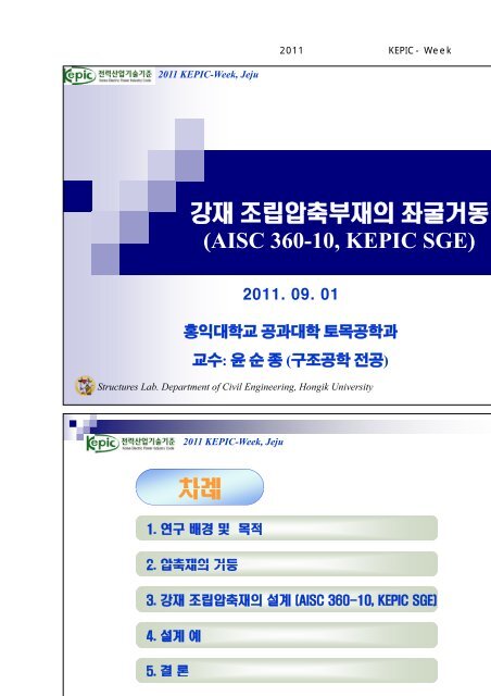
AISC 360-10, KEPIC SGE
AISC 360-10, KEPIC SGE
AISC 360-10, KEPIC SGE
- No tags were found...

You also want an ePaper? Increase the reach of your titles
YUMPU automatically turns print PDFs into web optimized ePapers that Google loves.
2011년도 대한전기협회 <strong>KEPIC</strong>-Week 발표자료 S1-22011 <strong>KEPIC</strong>-Week, Jeju (<strong>AISC</strong> <strong>360</strong>-<strong>10</strong>, <strong>KEPIC</strong> <strong>SGE</strong>) : ( ) )Structures Lab. Department of Civil Engineering, Hongik University2011 <strong>KEPIC</strong>-Week, Jeju Structures Lab. Department of Civil Engineering, Hongik University- 19 -
2011 <strong>KEPIC</strong>-Week, Jeju Structures Lab. Department of Civil Engineering, Hongik University2011 <strong>KEPIC</strong>-Week, Jeju Structures Lab. Department of Civil Engineering, Hongik University- 21 -
(Failure Modes)2011 <strong>KEPIC</strong>-Week, Jeju Overall LocalStructures Lab. Department of Civil Engineering, Hongik University2011 <strong>KEPIC</strong>-Week, Jeju (1) Flexural bucklingdydzP yEI2 02F(2) Torsional bucklingd EIdd 4 2P4 202zdzcr2 EKL / r21ECwFez GJ2 IP ( KL)(3) Flexural-torsional bucklingxzd I d d v d uECwGJ P Px Pyd A d d d4 2 2 2 0 4 2 02 002z z z zF ex F ez4FexFezHFe 1 112H F 2ex F ez Ix IyHI0Structures Lab. Department of Civil Engineering, Hongik University- 22 -
2011 <strong>KEPIC</strong>-Week, Jeju k b/t 0.425 0.43 E / Fy 1.277 4.000 6.9700.75 E / Fy1.33 E / Fy1.76 E / FyStructures Lab. Department of Civil Engineering, Hongik University 2011 <strong>KEPIC</strong>-Week, JejuPlate Buckling AnalysisaAribtrary SupportN xSimple Supp pporttbSimple Supp pportN xAribtrary SupportBuckling StrengthFcr k2 E2b12(1 ) t 2Structures Lab. Department of Civil Engineering, Hongik University- 23 -
2011 <strong>KEPIC</strong>-Week, Jeju F crDue to strain hardeningFcr [ 1.5]2E( KL / r)e1 F2 2eyInelastic Elastic <strong>10</strong>F 1.0 F yF cr= 0.877 .2 F y e0.39F yF cr= 0.658 2e . F y1.5 <strong>KEPIC</strong>-<strong>SGE</strong> (<strong>AISC</strong>/LRFD) F e=yStructures Lab. Department of Civil Engineering, Hongik UniversityF eFcr 12.3%0.877 F ey [ 1 1.5] F F r 0.3F y cr0.658 e2eFye2011 <strong>KEPIC</strong>-Week, Jeju Structures Lab. Department of Civil Engineering, Hongik University- 24 -
2011 <strong>KEPIC</strong>-Week, Jeju Structures Lab. Department of Civil Engineering, Hongik University2011 <strong>KEPIC</strong>-Week, Jeju Batten Angle shape Channel shape BattenStructures Lab. Department of Civil Engineering, Hongik University- 25 -
2011 <strong>KEPIC</strong>-Week, Jeju 0.75 E/ Fy Structures Lab. Department of Civil Engineering, Hongik University2011 <strong>KEPIC</strong>-Week, Jeju KL KL a r m r o ri22KL : rm KL : r o 2 2 KL KL a2 0.82 (12 r m r o ) rib h2riba/r i : a/r ib : a : r i : r ib : Structures Lab. Department of Civil Engineering, Hongik University- 26 -
2011 <strong>KEPIC</strong>-Week, Jeju a40,r KL KL a 40,i r m r r o i KL KLKai r m r o ri22K i : 0.5 for angles back to back: 0.75 for channels back to back: 0.86 for all other casesStructures Lab. Department of Civil Engineering, Hongik University2011 <strong>KEPIC</strong>-Week, Jeju G EI LEI L columnbeamStructures Lab. Department of Civil Engineering, Hongik University- 27 -
2e2011 <strong>KEPIC</strong>-Week, JejuyDouble-Angle l Shaped Sectionx xyP u , KxLx,KyLy,KzLz,FySelect a SectionDistance between Connectors KxLxKyLya rz Max. , rxry KLy KLy rzm rzoYesfor Welds or Fully Tightened Bolts1722 KLy KLy K i a a rz m ry r o i 40Nor for Snug-Tight Boltsz2 2 KL 18y KLy a rzm ryo ri2221 E2 E3 EC w 1F ex , F ey , F ez GJ222 2K xLx K yLy KzLz Ar 0 r x r y m4F ey F ez 4 F ey F ez H F e11 1 2 2 H Fey F ez F e = Minimum [F ey , F e1 ] e5F yF eb E 0.45t f F yNotbE 0.91f F yNoYesQ 1 . 0QYes11s 1.340 0. 76b Fyt E0.53 E b Fy t <strong>10</strong> Qs2QQs8 0 . 877eQ 1.5No F cr F y 2e YesNoF9 cr0 .658Q Q Fy22Stop Yes Pu Pn Pn = 0.85 Fcr AgStructures Lab. Department of Civil Engineering, Hongik University2011 <strong>KEPIC</strong>-Week, JejuMathcad Ver. 14Unitkips <strong>10</strong>00lbff ksi <strong>10</strong>00psipPa 1.450<strong>10</strong> 7 ksi MPa <strong>10</strong> 6 PaInput DataResistance Factor: c 0.85HomeFactored Load P u 200kipsEffective Length Factor K x 1 K y 1 K z 1Length L x 8ft L y 8ft L z 8ftYield Stress F y 36ksiModulus of Elasticity E 29000ksiPoisson's Ratio 0.3Shear Modulus of ElasticityEG 2( 1 )Structures Lab. Department of Civil Engineering, Hongik University- 28 -
2011 <strong>KEPIC</strong>-Week, JejuSectional properties of single angleSectional properties tabulated in the <strong>AISC</strong> Manual (<strong>AISC</strong> Third Edition)Area A g 5.80in 2 Long leg b 1 8inShort leg b 2 4inThickness1t 2 inAxis X-X Moment of inertia I x 6.75in 4 Radius of gyration r x 1.08inCentroid y 0 0.854inAxis Y-Y Moment of inertia I y 38.6in 4 HomeRadius of gyration r y 2.58inCentroid x 0 2.84inAxis Z-Z Radius of gyration r z 0.863inTorsional Properties Torsional constant J 0.501in 4 Warping constant C w 1.8in 6Structures Lab. Department of Civil Engineering, Hongik University2011 <strong>KEPIC</strong>-Week, JejuSectional Properties of double angleInput the type of double angle section ( SLBB, LLBB ), connector type ( weld, bolt, snugtighted bolt) and number of connectorsType "SLBB"3Batten 8 Connector_Type "Bolt"Number_Connector 3Where, SLBB and LLBB are the short leg back to back and long leg back toback, respectively.Using single angle sectional properties, double angle sectional properties can becaculated as followsGross areaHomeA 2g 2A gA 2g 11.6in 2Radius of gyrationr 2x r x if Type "SLBB"r y if Type "LLBB"r 2y 3.97in r 2z r zr 2x 1.08in r 2y 3.97in r 2z 0.863inStructures Lab. Department of Civil Engineering, Hongik University- 29 -
2011 <strong>KEPIC</strong>-Week, JejuFlexural-torsional properties tabulated in the <strong>AISC</strong> Manual al (<strong>AISC</strong> Third Edition)r 0 4.16in H 0.979C 2w C w 2J 2 J2 C 2w 3.6in 6 J 2 1.002in 4Substituting the member length and number of connectors, distance betweenconnectors measured along the member length can be caculated as followsK y L ya a 24inNumber_Connector 1Modfied Slenderness RatioDistance between centroids of individual components is defined as followsaccording to type of double angle sectionHomeh 2y 0 Batten if Type "SLBB"h 2.083in2x 0 Batten if Type "LLBB"r ib r yr ib 2.58inWhere, r ib is radius of gyration of individual component relating to its centroidalaxis parallel to the member axis of buckling (for double angle members it is r y )Seperation ratio is defined as followsh 0.4042r ibThe modified slenderness ratio is also dependent on the slip-resistance of theconnections. <strong>AISC</strong> LRFD Chapter E4.1 provides m K y L yif a 40inr 2yotherwise2 2 K y L y K i a r 2y r if Connector_Type 2y"Bolt" "Weld"2 K y L y 2a r r if Connector_Type 2y z"Snug Bolt"Structures Lab. Department of Civil Engineering, Hongik University m = 24.37 (<strong>AISC</strong> <strong>360</strong>-05) m 24.181 (<strong>AISC</strong> <strong>360</strong>-<strong>10</strong>)2011 <strong>KEPIC</strong>-Week, JejuBuckling StressThe elastic buckling stresses about the x, y, and z axes are defined as follows2 2 E 2 E EC 2wF ex F2 ey F2 ez K x L x m K z L z r 2x 2 GJ 2F ex 36.225ksi F ey 489.482ksi F ez 56.23ksi12A 2g r 0Using <strong>AISC</strong> LRFD-Formula A-E3-6, the flexural-torsional buckling stress can becalculated cu ated as follows o where e y is the axis of symmetryyF ey F ez 4F ey F ez HF e1 1 1 2H F ey F ez 2F e1 56.078ksiThe buckling stress is defined as the lowest of the elastic and flexural-torsionalbuckling stress obtained previoulsy. Thus,F 36 225k iF e min F ex F ey F e1F e 36.225ksiSlenderness ParameterUsing <strong>AISC</strong> LRFD-Formula F (A-E3-4), the slenderness parameter e is defined d asfollowsHomeF y e 0.997FeeStructures Lab. Department of Civil Engineering, Hongik University- 30 -
2011 <strong>KEPIC</strong>-Week, JejuRd Reduction FactorFlange widthb b 1 if Type "SLBB"b 8inb 2 if Type "LLBB"From <strong>AISC</strong> LRFD Appendix B-5.3a (a), reduction factor Q can be obtained asfollowsQ b1 if 0.45EQ 0.912t F yotherwise1.340 0.76b t F yEbif 0.91tEF y0.53E2otherwisebF y t HomeCritical Buckling StressFrom <strong>AISC</strong> LRFD-Appendix B-5 3d, the critical stress F cr is determined asfollowsF cr Q 0.658 Q 2 e Fy if e Q 1.5F cr 22.46ksi0.877F y otherwise2 eDesign StrengthCheckP n F cr A 2gP d c F cr A 2gP d 221.46kips P u 200kipsCheck "This section is O.K." if P u P d"N.G. Select a section again." otherwiseHomeCheck "This section is O.K."Structures Lab. Department of Civil Engineering, Hongik University2011 <strong>KEPIC</strong>-Week, Jeju Structures Lab. Department of Civil Engineering, Hongik University- 31 -