Band Structure and Electrical Conductivity in Semiconductors
Band Structure and Electrical Conductivity in Semiconductors
Band Structure and Electrical Conductivity in Semiconductors
- No tags were found...

You also want an ePaper? Increase the reach of your titles
YUMPU automatically turns print PDFs into web optimized ePapers that Google loves.
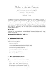
Conductionb<strong>and</strong>E fE gE d+As As As AsAs+ As+ EAs+ As+ As+As+ As+As+fE fValenceb<strong>and</strong>(a) (b) (c)Figure 5: Electron concentration of an n-type semiconductor <strong>in</strong> (a) low temperatureregime, (b) medium temperature regime, (c) high temperature regime. E f<strong>and</strong> E d are the Fermi <strong>and</strong> donor atom energy levels, respectively.slope=-E /2kgBlog(n)Intr<strong>in</strong>sicregionExtr<strong>in</strong>sicregion1/TIonizationregionslope=-∆E/2kBFigure 6: The temperature dependence of the electron concentration <strong>in</strong> an n-typesemiconductor, show<strong>in</strong>g the ionization, extr<strong>in</strong>sic <strong>and</strong> <strong>in</strong>tr<strong>in</strong>sic regimes. Note thatthe horizontal axis is 1/T <strong>in</strong>stead of T .Q 10. Explore the orig<strong>in</strong> of the extra factor of one half <strong>in</strong> Equation (15).2. Medium temperature regime In this temperature range, the processof ionization has cont<strong>in</strong>ued to the extreme that all donor atoms have beenionized as shown <strong>in</strong> Figure (5b). This temperature range is often calledthe extr<strong>in</strong>sic range <strong>and</strong> is also <strong>in</strong>dicated <strong>in</strong> Figure (6). S<strong>in</strong>ce the electricalconductivity depends on carrier concentration n <strong>and</strong> mobility µ,σ = qnµ, (16)<strong>and</strong> n = N d ≃constant <strong>in</strong> the extr<strong>in</strong>sic region, the conductivity is solelydeterm<strong>in</strong>ed by the temperature variation of the mobility. The mobility isproportional to some power α of the temperature,σ = T α . (17)9
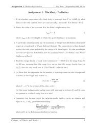
e -2K.E=(1/2)m evr cAs +K.EIP.EIK.E~IP.EI ∼Figure 8: Electron scatter<strong>in</strong>g by an ionized impurity (As + ) that is fixed <strong>in</strong> position.• If the K.E < |P.E|, then the columbic <strong>in</strong>teraction energy is strongenough to deflect the electron. The two cases are depicted <strong>in</strong> Figure (8).• K.E ≈ |P.E| at r = r c , the critical radius at which the electron is justscattered, lead<strong>in</strong>g to,32 k BT =e 2, (23)4πε o ε r rc2from which one can deuce the critical radius,r c =e 26πε o ε r kT . (24)log(µ)T 3/2 T -3/2Impurity Scatter<strong>in</strong>glog(T)Lattice Scatter<strong>in</strong>gFigure 9: Temperature dependence of mobility <strong>in</strong>clud<strong>in</strong>g effects of both lattice <strong>and</strong>impurity scatter<strong>in</strong>g <strong>in</strong> the two temperature regimes.Thus, the critical scatter<strong>in</strong>g radius r c also possesses the <strong>in</strong>verse temperaturedependence <strong>and</strong> decreases as temperature <strong>in</strong>creases. By add<strong>in</strong>gthe value of r c <strong>in</strong>to scatter<strong>in</strong>g cross section, S = πr 2 c, one may <strong>in</strong>fer that12
S ∝ T −2 . Therefore, the ionized impurity scatter<strong>in</strong>g limited mobility,µ I comes out as replac<strong>in</strong>g the same argument given before Equation (22)µ I ∝ T 3/2N I, (25)where N I is the ionized impurity concentration. Thus <strong>in</strong> the low temperatureregime, µ I decreases with <strong>in</strong>creas<strong>in</strong>g ionized impurity concentration.The lattice limited <strong>and</strong> impurity limited regimes of the mobility are shown <strong>in</strong> Figure(9). It is observed from Equations (22), (25) <strong>and</strong> Figure (9) that the mobilityhas a divergent behavior with respect to temperature. At low temperature, mobility<strong>in</strong>creases with <strong>in</strong>creas<strong>in</strong>g temperature, <strong>and</strong> starts decreas<strong>in</strong>g as temperature<strong>in</strong>creases <strong>in</strong> the high temperature regime.Q 13. Calculate the temperature dependence of the mean free time τ betweenimpurities <strong>and</strong> derive Equation (25).2.6 Temperature dependence of conductivityWe have determ<strong>in</strong>ed the temperature dependence of the carrier concentration <strong>and</strong>mobility for a doped semiconductor. Hence, the electrical conductivity <strong>in</strong> extr<strong>in</strong>sicsemiconductors can be determ<strong>in</strong>ed by comb<strong>in</strong><strong>in</strong>g the results of Figures (6) <strong>and</strong> (9),as shown <strong>in</strong> Figure (10).slope=-E /2kgBlog(n)log(n)Extr<strong>in</strong>sicregionslope=-∆E/2kBIntr<strong>in</strong>sicregionlog(µ)T 3/2 T -3/2Ionizationregion1/TFigure 10: Comb<strong>in</strong>ed effects of mobility <strong>and</strong> carrier concentration.13
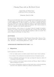
3 The experiment3.1 Overview of the experimentIn this experiment we will <strong>in</strong>vestigate the conductivity temperature variation of asemiconductor sample (the base region <strong>in</strong> the unijunction transistor UJT(2N2646)<strong>and</strong> pure germanium Ge). The conductivity is derived from the measured resistancewhile temperature is controlled by a controller <strong>and</strong> measured us<strong>in</strong>g athermocouple.The semiconductor sample is placed <strong>in</strong>side a sample cell. The sample cell is placed<strong>in</strong>side a flow cryostat which can be filled by liquid nitrogen. The cell is cooled bythe cool vapor of N 2 . Alternatively, the cell can be heated to elevated temperaturesby pass<strong>in</strong>g current through a heater wire wound around it. The flow cryostat issketched <strong>in</strong> Figure (11a) highlight<strong>in</strong>g the various components.The resistance of the semiconductor sample is measured by the four-probe technique[5], [6]. A constant current is passed through the sample. The current isgenerated by a constant current source. The voltage drop across the sample isacquired by a four-probe circuit <strong>and</strong> facilitated by a Labview programme. Tomeasure the temperature of the sample, a K-type thermocouple is placed <strong>in</strong>sidethe sample cell <strong>and</strong> the temperature control is achieved by a multi-zone controller.The measured resistance at different temperatures yields the conductivity versustemperature behaviour of the semiconductor sample, from which the energy b<strong>and</strong>gap E g <strong>and</strong> the temperature dependent coefficient of mobility α can be calculated.3.2 ApparatusThe experiment <strong>in</strong>volves the follow<strong>in</strong>g major components.1. cryostat2. sample cell conta<strong>in</strong><strong>in</strong>g the sample <strong>and</strong> wound with heater wire3. temperature controller4. thermocouple5. voltmeter with high <strong>in</strong>put resistance6. constant current source7. power supply for the constant current source8. solid state relay (SSR)9. data acquisition system (DAQ)14
FunnelInsulat<strong>in</strong>g lidsCryostatSampleIVPipeThermocoupleSample cellSample cellVariac100VInputThermocouple+5VOutput-5VSolid staterelay (SSR)(b)+- + -OutputChannelInputL1 ChannelL2 PowerTemperaturecontrollerSt<strong>and</strong>Liquid nitrogenHeat s<strong>in</strong>k(a)(c)Figure 11: Experimental setup: (a) cryostat with the sample cell, (b) circuitry ofthe temperature control setup, <strong>and</strong> (c) assembled view. I is the <strong>in</strong>put constantcurrent <strong>and</strong> V is the measured voltage.10. supply of liquid nitrogen N 2 .Follow<strong>in</strong>g some brief description of the above listed components. Our samples area dice of pure Ge (donated by Dr. S. A. Siddiqi (Punjab University) <strong>and</strong> extremelyexpensive!) <strong>and</strong> the base of a unijunction transistor UJT, which is a lightly n-typematerial.3.2.1 CryostatThe cryostat, shown <strong>in</strong> Figure (12a) is a copper cyl<strong>in</strong>der (4 <strong>in</strong>ch <strong>in</strong> diameter,12 <strong>in</strong>ch long with one end closed), used to ma<strong>in</strong>ta<strong>in</strong> cryogenic temperatures, <strong>and</strong>also able to withst<strong>and</strong> high temperatures. An <strong>in</strong>sulat<strong>in</strong>g sheet is wrapped aroundthe cyl<strong>in</strong>der for reduc<strong>in</strong>g heat losses.3.2.2 Sample cellFor high temperature measurements, the semiconductor sample is slowly heated<strong>in</strong>side the sample cell wound with nichrome heater wire (Nichrom 37). It is essentiallya copper pipe (20 mm diameter with one end closed). For low temperature15
(a)(b)Figure 12: (a) Cryostat. (b) Sample cell with heat s<strong>in</strong>k.measurement, a copper braid is attached to the bottom of the sample cell thatserves as a heat s<strong>in</strong>k, <strong>and</strong> is shown <strong>in</strong> Figure (12b). The heat s<strong>in</strong>k ensures goodthermal contact with liquid nitrogen. The sample cell is lowered <strong>in</strong>to the cryostatfor the measurements.3.2.3 ThermocoupleA thermocouple is a temperature sensor used to measure the sample temperature.It is made up of two different metals with the metals at one end jo<strong>in</strong>ed together.Whenever the junction of two metals is heated or cooled, voltage is producedthat can be correlated with temperature through a calibration procedure. In thisexperiment, we use a K-type thermocouple, for which some details are given <strong>in</strong>Table (1). The thermocouple read<strong>in</strong>g is fed <strong>in</strong>to a multi-zone controller.temperature rangecompositionsensitivity−200 o C to 1250 o CChromium-Alum<strong>in</strong>ium∼ 41 µV/ o CTable 1: Some characteristics of the K-type thermocouple.3.2.4 Temperature controllerOur aim is to atta<strong>in</strong> a stable temperature for the sample, for which a multi-zonecontroller (CN1504-TC from Omega Eng<strong>in</strong>eer<strong>in</strong>g) is used. It is a compact unitcompris<strong>in</strong>g four PID controllers, <strong>and</strong> is shown <strong>in</strong> Figure (13). Additionally, it isalso equipped with an ON/OFF control [8]. A temperature profile is programmed<strong>in</strong>to the controller to achieve a particular temperature for a certa<strong>in</strong> duration oftime. To obta<strong>in</strong> an underst<strong>and</strong><strong>in</strong>g of the programm<strong>in</strong>g modes <strong>and</strong> a guide to16
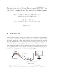
construct<strong>in</strong>g the profiles, refer to Appendix A or the datasheet of the controller[8].(a)(b)Figure 13: Temperature controller, (a) front view, (b) rear view.The advantage of the temperature controller is that it posseses a “Proportional,Integrator, Derivative” (PID) controller. The PID controller calculates an errorvalue as the difference between a measured process variable <strong>and</strong> a desired set po<strong>in</strong>t.For more details see Appendix B.Q 14. Read Appendix A. Programme a profile <strong>in</strong> the temperature controller.Your start<strong>in</strong>g po<strong>in</strong>t will be the room temperature, achieve 40 ◦ C <strong>in</strong> 1 m<strong>in</strong> <strong>and</strong> keepthe temperature fixed at 40 ◦ C for 10 m<strong>in</strong>utes. Subsequently, migrate to 50 ◦ C <strong>in</strong>1 m<strong>in</strong> <strong>and</strong> keep the temperature fixed at 50 ◦ C for 10 m<strong>in</strong>utes.The purpose of the previous step is to familiarize you with the programm<strong>in</strong>g of thetemperature controller. This step must be completed <strong>and</strong> practised beforethe start of the experiment.3.2.5 Four-probe versus two-probe methodResistance measurements are often taken by a two-probe method, that is depicted<strong>in</strong> the self-explanatory Figure (14a). The disadvantage of this method is thatsome voltage drop occurs across the lead resistance, hence the voltage measuredby the meter (V m ) will be different from the actual voltage (V r ) across the testresistance. So when applied to low test resistances (R x < 100 Ω), the voltagedrop due to current (I lead ) flow<strong>in</strong>g through the lead resistance can no longer beneglected, lead<strong>in</strong>g to significant error <strong>in</strong> the results.In order to remove the error of contact resistances, a four-probe method is preferred,specially when R x is small. In this method, current is passed through thetest resistance us<strong>in</strong>g one set of leads <strong>and</strong> voltage drop is measured through anotherset, as depicted <strong>in</strong> Figure (14b). Although small current may flow through the voltagemeasur<strong>in</strong>g leads but that would be much smaller, ow<strong>in</strong>g to the extremely large<strong>in</strong>put resistance of the voltmeter, <strong>and</strong> can generally be neglected for all practicalpurposes [6].17
R leadR leadIV mV mV rRXIV mR leadV rRxR leadR leadR leadV m =Votage measured by meterV r =Voltage across resistorMeasured resistance=V m= R+(2* R )I lead(a)-12VVMeasured resistance= mI(b)=V rIrc680Ω2.7VVz2.7kΩ0-5kΩ-+12VTL081rcRX-12V(c)-12V680Ω2.7KΩ2.7V-+0-5KΩ 1/4TL081AIBCRxD-+1/4TL084-+(d)1/4TL0841KΩ1KΩ1kΩ1KΩ-1/4TL084+Vo220VAC+18V-18VD2D3D4D1LM317+ve+ +C2=10µF- -C1=1000µF110Ω1kΩGND+-+12VC5=10µFC3=1000µF+ +- -(e)C4=10µF-veLM3371kΩ110Ω+-C6=10µF-12VFigure 14: The Electronic circuitry. (a) 2-probe method, (b) 4-probe method,(c) current source, (d) overall circuit show<strong>in</strong>g the current source <strong>and</strong> differentialamplifier, (e) DC power supply.3.2.6 Constant current source <strong>and</strong> voltmeterThe resistance of the semiconductor sample is measured by pass<strong>in</strong>g constant currentthrough the sample <strong>and</strong> measur<strong>in</strong>g the voltage drop generated across it. In18
order to provide stable current to the sample, a constant current generator is required<strong>and</strong> is shown <strong>in</strong> Figure (14c). You will be required to construct thisconstant current source. The sample resistance (R x ) is calculated from theoutput voltage as,R x = V oI(26)= R( V oV z), (27)where V z is the Zener voltage <strong>and</strong> V o is the output voltage that will ultimatelySemiconductor sample R x IUnijunction transistor (UJT) up to 10 kΩ 100 µAGermanium (Ge)
(a)(b)Figure 15: (a) open view, (b) closed view.3.3 Experimental procedure1. Make circuits for constant current sources of 100 µA, 10 mA <strong>and</strong> the voltmeteron bread board accord<strong>in</strong>g to the circuit diagrams <strong>in</strong> Figures (14c),(14d).2. You are provided with one unijunction transistor (UJT) <strong>and</strong> a dice of puregermanium (Ge). Current <strong>and</strong> voltage wires have already been connectedus<strong>in</strong>g silver pa<strong>in</strong>t with these samples, shown <strong>in</strong> Figure (16).current leadsceramic rodcurrent leads(a)(b)Figure 16: (a) Pure germanium Ge. (b) Unijunction transistor UJT.3. Pass the <strong>in</strong>sulated wires, enshrouded <strong>in</strong> a ceramic rod through the steelpipe. Connect current <strong>and</strong> voltage leads with constant current source <strong>and</strong>voltmeter. You will acquire voltage through the data acquisition system(DAQ).4. Before mak<strong>in</strong>g any electrical connection, set the output voltage of the variacto 100 V. Measure it with a voltmeter.5. Layout the experiment as suggested <strong>in</strong> Figure (11). Do not switch on powerat this satge.6. Connect the solid state relay (SSR) with the sample cell as well as withthe temperature controller, <strong>in</strong> a way that its positive term<strong>in</strong>al is connected20
to the positive output channel of the temperature controller, <strong>and</strong> negativeterm<strong>in</strong>al is connected with the negative output channel of the controller. Therema<strong>in</strong><strong>in</strong>g term<strong>in</strong>als are connected to the sample cell <strong>and</strong> variac, as sketched<strong>in</strong> Figure (11b).7. Open the Labview file titled energyb<strong>and</strong>.vi. Make a folder, <strong>and</strong> enter yourfile name (e.g D:\amrozia\test.lvm). Your data will automatically be saved<strong>in</strong> that file. You will use the DAQ system together with the Labview codeto measure the output voltage of the four-probe circuit.8. First set the variac at 100 V. Switch on the variac, the temperature controllerwill turn on. Leave the setup for 10 m<strong>in</strong>utes to warm up the temperaturecontroller.9. Turn on the DC power supply that is connected to the current source <strong>and</strong>voltmeter. Check the output of the voltmeter.10. UJT sample, low temperature measurement:• It will not be required to programme the temperature controller <strong>in</strong> thisphase of the experiment as the temperature is naturally <strong>in</strong>creas<strong>in</strong>g.• Add liquid nitrogen to the cryostat through the funnel.• The temperature controller will start show<strong>in</strong>g the correspond<strong>in</strong>g temperature.Pour liquid N 2 until you reach the temperature ∼ (−150 ◦ C).• Leave the setup to warm up to room temperature. As it warms, do thefollow<strong>in</strong>g.• Take voltage measurement after every 10 ◦ C rise <strong>in</strong> temperature us<strong>in</strong>gthe Labview file energyb<strong>and</strong>.vi.• Suppose, when the temperature controller shows −150 ◦ C. In the frontpanel, enter the value −150 ◦ C <strong>in</strong> the temperature box. Press the runbutton to start acquir<strong>in</strong>g data <strong>and</strong> the stop button to stop the acquisition,while the temperature is still −150 ◦ C.• Open Matlab, <strong>and</strong> add the appropriate folder to the Matlab path.• Take the mean of the voltage value at the different temperatures.11. UJT sample, high temperature measurement:• When you have reached room temperature, you will start tak<strong>in</strong>g yourread<strong>in</strong>gs for higher temperatures. For this purpose, you will require theuse of the heater <strong>and</strong> the PID controller.• Suppose you want to take read<strong>in</strong>gs <strong>in</strong> steps of 10 ◦ C, rang<strong>in</strong>g from 40 ◦ C,50 ◦ C, up to 250 ◦ C.• Suppose the room temperature is 32 ◦ C.• Now we need to enter a profile so that the temperature negotiates 40 ◦ C,50 ◦ C <strong>and</strong> 60 ◦ C, as it is only possible to programme for these threepo<strong>in</strong>ts at one time. Now enter this temperature profile accord<strong>in</strong>g to the<strong>in</strong>structions <strong>in</strong> Appendix A.21
• Acquire the voltage for 40 ◦ C, 50 ◦ C <strong>and</strong> 60 ◦ C us<strong>in</strong>g Labview as discussesearlier.• For the next set of po<strong>in</strong>ts (e.g 70 ◦ C, 80 ◦ C, 90 ◦ C), you will have to repeatthe above steps.• Complete your measurements up to ∼ 250 ◦ C.• F<strong>in</strong>d resistance from the acquired voltage.• Tabulate temperature versus resistance, as <strong>in</strong>dicated <strong>in</strong> Table (3).Temperature ( ◦ C)−150−140..250Resistance (Ω)Table 3: Relationship between temperature <strong>and</strong> sample resistance.12. Ge sample, high temperature measurement:• You are provided with a pure Ge sample, an <strong>in</strong>tr<strong>in</strong>sic semiconductor.Set up the complete experiment be<strong>in</strong>g guided by your experience withthe UJT sample. The constant current for the Ge sample is I = 10 mA.• Aga<strong>in</strong> enter the temperature profile <strong>in</strong> the temperature controller. Youwill require measurements up to 150 ◦ C.• Complete acquir<strong>in</strong>g the data.• Tabulate temperature versus resistance.Q 18. Plot a graph of log( 1 ) versus T <strong>in</strong> Kelv<strong>in</strong>s, <strong>and</strong> dist<strong>in</strong>guish the <strong>in</strong>tr<strong>in</strong>sicR<strong>and</strong> extr<strong>in</strong>sic regions for the UJT.Q 19. Calculate the energy b<strong>and</strong> gap from the <strong>in</strong>tr<strong>in</strong>sic region data for UJT<strong>and</strong> Ge. As conductivity depends on both the charge carrier concentration <strong>and</strong>mobility, so <strong>in</strong> calculat<strong>in</strong>g b<strong>and</strong> gap take both of these factors <strong>in</strong>to account. Thepublished energy b<strong>and</strong> gap values for silicon (Si) <strong>and</strong> germanium (Ge) are provided<strong>in</strong> Table (4).SemiconductorSilicon (Si)germanium (Ge)<strong>B<strong>and</strong></strong> gap1.12 eV0.67 eVTable 4: Energy b<strong>and</strong> gap (E g ) for Si <strong>and</strong> Ge.Q 20. Calculate the temperature coefficient α of the carriers mobility from theextr<strong>in</strong>sic region data of the UJT. The published value of α is 2.3, given <strong>in</strong> [10].22
Q 21.What is your uncerta<strong>in</strong>ty <strong>in</strong> the energy b<strong>and</strong> gap measurement?Q 22. In the low temperature measurements, the sample is cont<strong>in</strong>uously thaw<strong>in</strong>g(warm<strong>in</strong>g) as data is be<strong>in</strong>g acquired. What k<strong>in</strong>d of uncerta<strong>in</strong>ty does this cause<strong>in</strong> your measurements?AHow to construct a temperature profile <strong>in</strong> temperaturecontrollerSuppose we want to make the temperature profile, sketched <strong>in</strong> Figure (17). Forthis you have to do the follow<strong>in</strong>g steps.Temperature range ( C)o60504032Setpt#3Setpt#4Setpt#1 Setpt#2 10 m<strong>in</strong>1 m<strong>in</strong>10 m<strong>in</strong>1 m<strong>in</strong>0TimeSetpt#510 m<strong>in</strong>1 m<strong>in</strong>Setpt#6Figure 17: An example of temperature profile. Setpt#1, 2 is 40 ◦ C, setpt#3, 4 is50 ◦ C, <strong>and</strong> setpt#5, 6 is 60 ◦ C.1. The very first <strong>and</strong> the most important step is to power up thetemperature controller. Power connections should be made to L1, L2.L1 is connected to the positive term<strong>in</strong>al of the AC power supply <strong>and</strong> L2 withthe negative one. Our AC power supply is the variac, <strong>and</strong> it should be set at100 V. Be careful <strong>in</strong> apply<strong>in</strong>g voltage to the temperature controlleras it can be damaged, if you operate it over 120 V AC.2. To enter <strong>in</strong>to the programm<strong>in</strong>g mode, hold the CTR.SEL key until the unitdisplays EntEr PASSCOde. At this po<strong>in</strong>t, enter the pass code which is3254 for our device.3. Select programme system PrG SYS mode, the controller will enter <strong>in</strong>tothe system configur<strong>in</strong>g mode. Push PROG key, the display will show dSPOPt, select Process-Setpo<strong>in</strong>t. You have to push PROG key to go to thenext mode. The display will show dSPLy t, enter time <strong>in</strong> seconds us<strong>in</strong>g <strong>and</strong> < DIG > keys. The <strong>and</strong> < DIG > keys are used to assign values.Select Strt SP mode. Assign a value of 10 to rAtE tb mode. Enter COLdJN value that would be the room temperature. Enter a value of 10 to the23
V rAnGE mode <strong>and</strong> next to it, assign value to the C RAnGE that wouldbe 20.4. Move to the programme control PrG Ctr mode. Push PROG key, thedisplay shows CntrL x (where x=controller no.), select controller 1. Thengo to Ct tYPE mode <strong>and</strong> select PID option. Select Cr.Al (for the K-type thermocouple) for SIGnAL mode. Then select dEGrE C <strong>and</strong> f<strong>in</strong>ally,select eng<strong>in</strong>eer<strong>in</strong>g unit mode Cx UNIt that would be C if <strong>in</strong>put signal is athermocouple.5. Next move to the tun<strong>in</strong>g mode. Push PROG key until the unit displaystUnIng. Select the PID mode. Enter the follow<strong>in</strong>g values as,• proportional b<strong>and</strong> = 0.5,• reset = 1,• rate = 1.6. Push PROG key to enter <strong>in</strong>to profile mode. When the unit displays thePROFILE, select the required controller (controller 1) us<strong>in</strong>g PROG key.When the display will briefly read Strt SP, enter the value of start<strong>in</strong>g setpo<strong>in</strong>t that would be room temperature, for example 32 ◦ C as <strong>in</strong>dicated <strong>in</strong>Figure (profile). Use <strong>and</strong> < DIG > keys to enter the desired value. Nextpress SETUP to go to the next function. At this po<strong>in</strong>t the display willbriefly read SetPt 1 enter the value of setpo<strong>in</strong>t 1, for example 40 ◦ C. PushPROG key to go on to the next step. The display will show EntEr t, enterthe time value like 1 m<strong>in</strong>. Move to setpo<strong>in</strong>ts 2 by press<strong>in</strong>g PROG key. Entersetpo<strong>in</strong>t 2 value which is 40 ◦ C <strong>and</strong> time=10 m<strong>in</strong>. Repeat the above steps toprogram up to setpo<strong>in</strong>t 6 as shown <strong>in</strong> Figure (17).7. Push EXT key. Aga<strong>in</strong> push EXT key for sav<strong>in</strong>g programme. Select thedesired controller us<strong>in</strong>g PROG key <strong>and</strong> run it by press<strong>in</strong>g RUN/STOPkey.BPID controllerThe PID controller manipulates the process <strong>in</strong>puts based on the history <strong>and</strong> rateof change the signal [9]. The basic idea is that the controller reads the system bya sensor as shown <strong>in</strong> Figure (18a). Then it subtracts the measurement from thedesired reference to generate the error value. The error will be managed <strong>in</strong> threeways: to h<strong>and</strong>le the present through the proportional term; recover from the pastus<strong>in</strong>g the <strong>in</strong>tegral term; <strong>and</strong> to anticipate the future through the derivative term.B.1 Proportional termThe proportional term (sometimes called ga<strong>in</strong>) changes the output <strong>in</strong> proportion tothe present error value. The proportional response can be adjusted by multiply<strong>in</strong>g24
PK e(t) psetpo<strong>in</strong>tΣerrorItK i e(t)0ΣprocessoutputDK dd e(t)dt(a)sensorsetpo<strong>in</strong>tovershootresponserise timesteady-state errortime(s)(b)Figure 18: (a) Block diagram of a PID controller. (b) Response of a PID closedloop system.the error by a constant K P called the proportional ga<strong>in</strong>. A high proportional ga<strong>in</strong>results <strong>in</strong> a large change <strong>in</strong> the output. If the proportional ga<strong>in</strong> is too high, thesystem can become unstable. In contrast, a small ga<strong>in</strong> results <strong>in</strong> a small outputresponse, <strong>and</strong> a less responsive controller.B.2 Integral termThe <strong>in</strong>tegral term (sometimes called reset) is proportional to both the magnitude<strong>and</strong> duration of the error. This term sum up the previous errors to the system control<strong>in</strong>put. The summ<strong>in</strong>g of the error will cont<strong>in</strong>ue until the system process valueequals the desired value, <strong>and</strong> this results <strong>in</strong> no stationary error. The magnitude ofthe contribution of the <strong>in</strong>tegral term correction is determ<strong>in</strong>ed by the <strong>in</strong>tegral ga<strong>in</strong>K i .25
B.3 Derivative termThe derivative term (also called the rate) calculates the rate of change of theprocess error by determ<strong>in</strong><strong>in</strong>g the slope of the error over time. The magnitude of thecontribution of the derivative term to the overall system is determ<strong>in</strong>ed by the termK d . The derivative term slows the rate of change of the controller output. However,derivative control is used to reduce the magnitude of the overshoot produced by the<strong>in</strong>tegral term <strong>and</strong> improve the controller-process stability. If the derivative termis too large, it can cause the process to become unstable as this term is highlysensitive to noise <strong>in</strong> the error.26