Design Report.pdf - Eskom
Design Report.pdf - Eskom
Design Report.pdf - Eskom
- No tags were found...

You also want an ePaper? Increase the reach of your titles
YUMPU automatically turns print PDFs into web optimized ePapers that Google loves.
PCEmail:Peter Legg ConsultingGeo-Environmental Engineers28 8 th Avenue, Northmead, Benoni, 1501, South AfricaTel/Fax: +27(0)11 425 1197 Cell: +27(0)82 881 8090peterlegg@telkomsa.netFINAL DESIGN AND OPERATING PLANREPORT FOR THE EXTENSION OF THETUTUKA POWER STATION LANDFILL SITE<strong>Report</strong> No:P029-02Submitted to:Zitholele Consulting (Pty) LtdP.O. Box6002HalwayHouse1685DISTRIBUTION:1Copy - ZitholeleConsulting (Pty) Ltd1Copy <strong>Eskom</strong>GenerationEnvironmental Management1Copy Tutuka Power Station1Copy - Peter Legg ConsultingMay2010P029Sole Proprietor: P A Legg, PrEng
May2010 i P029-02TABLE OF CONTENTSSECTIONPAGE1 INTRODUCTION.................................................................................... 11.1 Background and Terms of Reference................................................ 11.2 Objectives.......................................................................................... 11.3 Scope................................................................................................ 22 SITE CLASSIFICATION ANDWASTE DISPOSALNEED...................... 32.1 Introduction........................................................................................ 32.2 Waste Types and Origin.................................................................... 32.3 Size of the Waste Stream and Landfill Airspace requirements........... 42.3.1 Size of waste stream............................................................ 42.3.2 Landfill airspace requirements............................................. 52.4 Potential for leachate generation....................................................... 52.4.1 Climatic water balance......................................................... 52.5 Discussion......................................................................................... 63 SITE DESCRIPTION.............................................................................. 63.1 Introduction........................................................................................ 63.2 Location, Size, Ownership and Current Land-use.............................. 83.3 Topography and Drainage................................................................. 93.4 Climate.............................................................................................. 93.5 Flora and Fauna................................................................................ 93.6 Geology, Soils and Groundwater.....................................................103.6.1 Geology.............................................................................103.6.2 Site Soils............................................................................113.7 Groundwater....................................................................................123.8 Discussion.......................................................................................144 PRELIMINARY DESIGN OFTHELANDFILL FACILITY.......................154.1 Introduction......................................................................................154.2 Constraints and factors affecting the design....................................154.3 General site layout...........................................................................164.4 Services and infrastructure..............................................................174.4.1 Access and Roads.............................................................174.4.2 Weighbridge.......................................................................174.4.3 Laboratory .........................................................................174.4.4 Fencing..............................................................................184.4.5 Water.................................................................................184.4.6 Electricity...........................................................................184.4.7 Staff facilities......................................................................184.4.8 Plant maintenance facilities................................................184.5 Landfill design .................................................................................184.5.1 <strong>Design</strong>approach................................................................184.5.2 Existing landfill capping and initial landfill development......194.5.3 Phase 1landfill development.............................................194.5.4 Development plan..............................................................204.6 Leachate and drainage management..............................................214.6.1 Upslope storm water drainage...........................................214.6.2 Contaminated surface run-off.............................................214.6.3 Leachate Management......................................................224.7 Linerdesigns...................................................................................234.7.1 Landfill liner (G:S:B - )..........................................................234.7.2 Existing landfill “Piggy-back” liner.......................................23PETERLEGG CONSULTING
May2010 ii P029-024.7.3 Contaminated water pond liner (G:S:B - ).............................244.7.4 Existing landfill final cover..................................................244.7.5 Construction Quality Assurance.........................................244.8 Landfill Gas Management................................................................244.9 Closure and End-use.......................................................................254.9.1 Final landform and end-use...............................................254.9.2 Closure and rehabilitation..................................................264.10 Discussion.......................................................................................265 PRELIMINARY OPERATING PLAN.....................................................275.1 Introduction......................................................................................275.2 Access.............................................................................................275.3 Control.............................................................................................275.3.1 Waste reclaimers...............................................................275.3.2 Waste acceptance.............................................................285.3.3 Records.............................................................................285.3.4 Auditing..............................................................................285.3.5 Landfill gas monitoring.......................................................285.4 Water Quality Monitoring.................................................................295.4.1 Background analyses.........................................................295.4.2 Surface water.....................................................................295.4.3 Ground water.....................................................................295.4.4 Leachate and contaminated water.....................................305.4.5 <strong>Report</strong>ing...........................................................................305.5 Recycling.........................................................................................305.6 Landfilling operation ........................................................................305.6.1 Cell Operation....................................................................305.6.2 Cover.................................................................................315.6.3 Wet weather cell................................................................315.7 Landfill Drainage..............................................................................315.8 Resources.......................................................................................325.8.1 Plant..................................................................................325.8.2 Staffing ..............................................................................325.9 Control of Nuisances.......................................................................335.10 Development Plan...........................................................................345.11 Rehabilitation...................................................................................345.12 Closure plan....................................................................................345.13 Discussion.......................................................................................346 CONCLUSIONS...................................................................................357 RECOMMENDATIONS........................................................................368 REFERENCES.....................................................................................36LIST OF FIGURESFigure1Figure 2Figure 3Figure4Location ofalternativecandidatelandfill sitesSiteLocalityPlanGeological Mapshowing theTutukaPower StationsiteUnsaturated zone /depth to top of groundwater table in meters below groundlevelPETERLEGG CONSULTING
May2010 iii P029-02LIST OF APPENDICESAppendixAAppendixBWasteGenerationandLandfill Airspace RequirementsDrawingsPETERLEGG CONSULTING
May2010 1P029-021 INTRODUCTION1.1 Background andTerms of Reference<strong>Eskom</strong> has ageneral waste landfill site within thepremises of theTutuka Power Station complex thatreceives general waste(including building rubbleand garden waste) from the power station itself, aswell as from the nearbytownship of Thuthukani and theNew Denmark colliery. The landfill site waspermitted in terms of Section 20 of the Environment Conservation Act in August 1994 as aClass 2Domestic Waste Disposal Site, with Permit No B33/2/3/310/45-P129. The landfill has reached itscapacity in terms of the permit requirements, and waste is currently being sent to the Kriel landfill.<strong>Eskom</strong> would therefore like to extend the footprint of the existing landfill, to provide an additionaldisposal capacityfor thenext 40 years.Zitholele Consulting has been appointed by <strong>Eskom</strong> to carry out the EIA, EMP, Landfill LicenceApplication, <strong>Design</strong> and Operating Manual for the landfill extension. Zitholele Consulting hassubsequently appointed Peter Legg Consulting as its engineering consultant for the survey of thelandfill site, geotechnical investigation, design and operatingplan for theproposedlandfill extension.This report covers the engineering design and operating plan for theproposed extension of the TutukaLandfill Site.1.2 ObjectivesThe overall project objectiveis to providean environmentally acceptable landfill to accommodatethegeneral solid waste disposal needs of the Tutuka Power Station, Thuthukani Township and NewDenmarkColliery for the next 40 years.More specifically,the objectives ofthis preliminarydesignphaseareas follows:• To classify the waste disposal facility in terms of waste types, size of waste stream and thepotential for leachategeneration.• To confirm the suitability of the existing landfill site and surrounds for the development of thelong-term wastedisposal facility.• To develop apreliminary design and operating plan for the landfill site that meets the disposalneed and that incorporates the necessary precautionary measures to mitigate the identifiedenvironmental impacts and critical factors.• To providerecommendations for the closureandrehabilitationofthe existinglandfill site.The purpose of this <strong>Design</strong> <strong>Report</strong> is to document the design criteria, assumptions and preliminarydetails of the proposed waste disposal facility, for the purpose of incorporation into the WasteManagement Licence Application andEIA reports to be submitted to the regulatoryauthorities. Onceauthorisation is obtained, the detailed design, tender process and construction of the facility canproceed.PETERLEGG CONSULTING
May2010 2P029-021.3 ScopeThe scope of the Preliminary <strong>Design</strong> relates to the design of a waste management facility thataddresses the waste disposal needs of the Tutuka Power Station, Thuthukani township and NewDenmarkColliery, andthat mitigates thepotential impacts the facilitycould have ontheenvironment,includingthesocio-economicandbiophysical environments.The design of the Tutuka Landfill siteis based onthe “MinimumRequirements –WasteManagementSeries”, second edition of 1998, specificallythefollowingdocuments:• Minimum Requirements for WasteDisposal byLandfill (1) .• Minimum Requirements for Monitoring at WasteManagement Facilities (2) .The Minimum Requirements for Waste Disposal by Landfill addresses landfill classification, siteselection, investigation, design, operation and monitoring of landfill sites. In thelandfill classificationsystem, alandfill is classified in terms of waste class, size of operation, and potential for significantleachate generation, all of which influence the risk it poses to the environment. Graded requirementsarethenset forall aspects oflandfill designand operation, including publicparticipation.Thescopeofthis report thereforeincludes the following:• Determination of the waste disposal need in terms of the types and quantities of waste to bemanaged and disposed of at the site, and hence the airspace and leachate managementrequirements.• Descriptionof thesiteand surrounds based on various siteinspections andprevious investigationscarried out.• Preliminary design of the waste disposal facility which includes site access, drainage, facilitiesand infrastructure, cell development and sequencing, leachate management, rehabilitationmeasures andmonitoring systems.• Apreliminary operating plan which outlines the operating procedures for all aspects of thefacility.• Preliminarydesignfor the closureandrehabilitationof theexistinglandfill.Although the original terms of reference called for alandfill with asite life until 2030 (20 years),<strong>Eskom</strong>has instructed that the newlandfill shouldhaveadesign sitelifeof40 years.PETERLEGG CONSULTING
May2010 3P029-022 SITE CLASSIFICATION AND WASTE DISPOSAL NEED2.1 IntroductionIn order to design alandfill facility that would meet the waste disposal needs of Tutuka PowerStation, Thuthukani township and New Denmark Colliery for aperiod of 40 years, it is necessary toqualify and quantify the current and future waste streams. An estimate of current waste generationvolumes is necessary to forecast future waste generation volumes, and hence landfill airspaceutilisation. Forecastingis donebyevaluatingand extrapolating existingor historic data.As the design of the landfill facility is to be based on the Minimum Requirements (1)(2) ,the landfillneeds to be classified in terms of the Minimum Requirements, so as to determine the technical andoperational standards towhichthefacilityhas tocomply.The Minimum Requirements’ landfill classification system defines the disposal situation or needaccordingtothe:• Wastetype• Size of the wastestreamandlandfill operation• Potential for significant leachate generation, and theneed for leachate management.These factors will determine the potential impact of the waste facility on the receiving environmentand public health. The Tutuka landfill facility has been classified on the current and projected wastestream, and onconditions at the existinglandfill site.The site classification has been carried out by Golder Associates Africa and reported in <strong>Report</strong> No12330-9390-1 “Tutuka Power Station -Classification of New and Current Tutuka Disposal Site”,January2010 (3) .This section thereforegives a short summaryoflandfill siteclassification.2.2 Waste Types and OriginTherearetwo genericcategories of waste, General andHazardous,accordingtotheriskthat eachtypeposes. Thesearedefinedas follows:General waste is normally municipal solid waste, comprising rubble, garden, domestic, commercialand general dry industrial waste. It may also contain small quantities of hazardous substancesdispersed within it, such as batteries, insecticides, weedkillers, fluorescent tubes and householdmedical waste such as usedplasters andbandages.Hazardous waste is waste which, on account of its inherent properties such as toxicity, corrosivity,ignitability or carcinogenicity, has the potential to have asignificant adverse effect on public health,eveninsmall quantities.PETERLEGG CONSULTING
May2010 4P029-02Since the design of awaste disposal facility relates to the risk posed bythe wastes disposed, designspecifications for ageneral waste facility would be considerably less stringent than those for ahazardous wastefacility.Hazardous waste generated at Tutuka Power Station is either disposed of on the station’s permittedhazardous wastedisposal facilityat theashdumps, or it is sent to acommercial hazardous waste site.The existing general waste landfill site currently receives solid waste from the following mainsources:Tutuka Power Station:- Domestic/office waste, garden waste, building rubble from station cleaningoperations, horticultural operations and maintenance workbycontractors.New Denmark Colliery:- Domestic/office waste, garden waste and building rubble from the minesoffices, plant andhostel.Thuthukani Township:- Domestic waste, garden waste and building rubble from the residences andbusinesses inthetownship.No hazardous waste is disposed of at the Tutuka landfill site. The existing landfill and its proposedextensionwouldthereforebeclassifiedas aGeneral (G) wastelandfill site.2.3 Size of the Waste Streamand Landfill Airspace requirements2.3.1 Size of waste streamIn the site classification report (3) ,the size of the waste stream was analysed using records of wastedeposited on Tutuka landfill site since its commissioning circa 1993. From this analysis, it wasdetermined that the current rate of deposition on the landfill is approximately 35 tonnes per day,based on 260 days of deposition in the year. This would therefore represent the initial rate ofdeposition (IRD) for determining the size classification of the site. After consideration of variouswaste stream growth rates during the life of the existing landfill site, it was decided to use agrowthrateof 3.7% perannum, for determining themaximum rateof deposition(MRD) at the end of the sitelife, and for calculating thelandfill airspacerequired for 40 years of wastedisposal.UsingtheMinimum Requirements procedure for calculating theMRD:MRD =(IRD)(1+d) tWhere: IRD =34 T/dd=3.7%t=40 yearsMRD =149.7T/dSincetheMRD is between 25 T/dand150 T/d, the sitewould classifyas aSmall (S) landfill site.PETERLEGG CONSULTING
May2010 5P029-022.3.2 Landfill airspace requirementsFor the 40 year life of the site, the total mass of general waste to be disposed of would beapproximately 845 000 tonnes, assuming no reduction due to composting or recycling. With anassumed in-situ landfill density of 1000 kg/m 3 and acover to waste ratio of 1:5, the total landfillairspacerequiredis 1014000 m 3 .This would requireapproximately167 000 m 3 ofcover material foraproper sanitarylandfill operation.Details ofthelandfill airspacecalculations areincluded inAppendix 1.2.4 Potential for leachate generationThepotential for significant leachategeneration depends onthe water balance associatedwith awastedisposal site. This is dictated by ambient climatic conditions or by other site specific factors such asthemoisturecontent of theincoming waste and/or ingress ofeither groundwater or surfacewater runofffrom high groundintothe wastebody.2.4.1 Climaticwater balanceThe climatic water balance for the Tutuka Landfill site was calculated and included in the siteclassificationreport (3) ,according tothefollowing equation:B=R–EwhereBis theclimaticwater balancein mm.Ris rainfall in mm.Eis the evaporation from asoil surface in mm, taken as 0.7 xA-pan evaporation in mm or0.88 xS-panevaporation in mm.The value of B is calculated for the wet season ofthe wettest year onrecord. It is thenrecalculated forsuccessive drier years until it is established whether Bis positive for less than one year in five for theyears for which datais available. If so, thefollowing criteriaapply:• No significant leachategeneration.• Classified B -• Noleachatemanagement systemnecessary.or Bis positive for more than one year in five for the years for which data is available. If so, thefollowing criteria apply:• Significant leachategeneration canbeexpected• Classified B +PETERLEGG CONSULTING
May2010 6P029-02• Aleachatemanagement systemis aMinimum RequirementFor the climatic data available for the Tutuka area (rainfall and evaporation), Bwas found to benegative for nine of theten years of climaticdata used. This means that thelandfill is not expected togeneratesignificant leachate.Other factors that could affect the water balance of awaste site include the moisture content of theincoming waste, and the ingress of groundwater and/or surface water into the waste body due to poorsiting, designandmaintenanceofthe site.No significant volumes of high moisture content wastes are expected to be received at the site.Provided that upslope surface water drainage systems are installed to prevent the ingress ofstormwater runoff onto the waste body, the site water balance should not be affected and significantleachategeneration should not beexpected.Based on the above, the Tutuka landfill site is therefore classified as aB - waste disposal facility. Interms of the Minimum Requirements, it should not be necessary to install aleachate managementsystem. However, based on the fact that the existing landfill has already impacted negatively on thegroundwater environment, it would be advisable to install abottom liner and leachate detection andcollectionsystem onthenewlandfill.2.5 DiscussionThe design of the Tutuka landfill facility must make provision for approximately 1014 000 m 3 ofgeneral wastedisposal airspace for the 40 year designlife.Thelandfill operationandinfrastructure will havetoaccommodateawaste stream of up to 150 tonnesper day.On account of the negative climatic water balance, significant leachate generation from thelandfill isunlikely, and a formal leachate management is not required. However, a leachate detection andcollectionsystem should beinstalledas aprecautionarymeasure.Based ontheforegoing, theTutuka landfill facilityis to classifiedas aG:S:B - wastedisposal facility.3 SITE DESCRIPTION3.1 IntroductionAs part of the EIA process for the development of the new waste disposal facility, anumber ofalternative candidate landfill sites were identified on <strong>Eskom</strong>/Tutuka Power Station property. Thesesites were visited and evaluated according to various technical, economic, environmental and publicacceptance criteria. Sites where potential fatal flaws were identified were eliminated as candidatelandfill sites. Theremaining candidate sites werethen scored for each criterion, and ranked inorder ofPETERLEGG CONSULTING
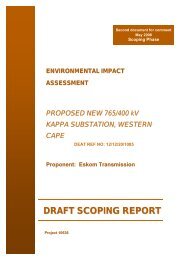
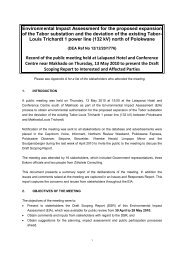
May2010 7P029-02suitability. Based on this evaluation and ranking process, the most suitable candidate landfill site(Alt3) turned out to be the area immediately to the west of the existing landfill, followed by the twoadjacent areas immediately southwest (Alt 4) and south (Alt 2) of the existing landfill site. Thesealternative sites are indicated on Figure 1. It was therefore decided that the new Tutuka landfillfacility should be developed as an extension to the existing landfill, in the area immediatelyadjacenttothewest sideofit.Figure 1:Location ofalternative candidatelandfillsitesIf feasible, it would be preferable to integrate the new landfill into the existing landfill by extendingthe footprint and raising the current height of the landfill. Based on preliminary estimates, atotalfootprint ofapproximately8.48 ha will berequiredtoprovide sufficient airspace for 40 years of wastedisposal. This will be achieved byusing the existing landfill footprint together with the area betweenthe current landfill and the borrow pit to the west, and by extending the landfill in asoutherlydirection.The area of the existing landfill site and surrounds has been surveyed to determine topography,significant features such as trees, roads, fences, drains, buildings, tracks, boreholes and drainagecourses, see Drawing No 12333/01. The positions of the ten testpits excavated and profiled as part ofthe geotechnical investigation are shown on Drawing No 12333/02. These testpits were positioned inthearea proposedfor the newlandfill site. Thedrawings areincludedinAppendix B.PETERLEGG CONSULTING
May2010 8P029-02The area of the waste site is described to produce an overview of the status quo of the site and itscurrent impact on the environment, and to identify problems or factors that would need to beaddressedinthe design.3.2 Location, Size, Ownership and Current Land-useThe landfill site is located approximately 2km to the west of Tutuka Power Station precinct on thefarm Pretorius Vley374 IS, on propertythat is owned by<strong>Eskom</strong>. This entire propertyhas been zonedfor industrial use. Thepermittedlandfill site covers an area of 3.224 ha, althoughthe landfill itselfhasafootprint area of 2.543 ha. The area available for the new landfill is in excess of 50 ha, which is fargreater than required. Thesiteis located within ahighly disturbed area as aresult of extensive gravelexcavation operations for the power station site. Thelandfill itself was sited within aprevious borrowpit, although there is asmall area of undisturbed land approximately100 mwide immediately to thewest of the landfill. To the west of this undisturbed area, and to the east of the landfill, there isevidenceofgravel excavations,resultinginahighlyuneven ground surfaceand ponded water.Thelocation ofthe siteis indicatedonFigure2.Figure 2:Sitelocality planThe current landfill is approximately 250 mlong by 100 mwide, and is 7mabove natural groundlevel at its northern end. At the southern end, the landfill surface is at ground level. There is anupslope stormwater diversion drain along the southern side of the landfill that drains in awesterlydirection to the borrow pit on the west side. Access to the landfill site is bymeans of agravel roadfrom the south side, which then runs along the western toe of the landfill. Cover material for thePETERLEGG CONSULTING
May2010 9P029-02landfilling operations is obtained from adoleriteborrow pit approximately400 mto the south west ofthelandfill.3.3 Topographyand DrainageThe site is situated in sub-catchment C11K-B and has been developed upon gradual slopes and asemi-developed drainage system. An east-west trending ridge that falls to more moderately slopingcountry defines the southern boundary of the site. On the eastern side of the site, surface relief isgently sloping at approximately3% in anortherly directiontowards an ephemeral stream that flows inanorth westerly direction past the northern side of the landfill towards the Racesbult Spruit. TheRacesbult spruit in turn flows inawesterly direction intothe Leeuspruit. The ridge terminates alongthe western boundary of the property, where the country falls steeply towards the Leeu Spruit. TheLeeu Spruit drains the area to the west of the site to the Grootdraai Dam, an artificial impoundmentconstructed across the Vaal River approximately10 km fromthesite.3.4 ClimateThe site falls withinthe summer rainfall region of the Highveld, with warm, wet summers, and mild,dry winters, with annual equivalent evaporation depths exceeding precipitation. Winds blowpredominantly from the northwest, particularly in the afternoon, although they do gust from thesouthwest during thunderstorm events. Regular dust storms can also be expected during periods ofprolonged dry weather.Air temperatures show significant daily and seasonal variations, with mean temperatures at theirmaximum in December and January (27 0 C), and minimum in June and July (-1 0 C). Frosts can beexpectedin the150-dayperiodbetween Mayand September.Average annual rainfall is about 680 mm, whilst average annual evaporation is about 1780 mm. Thesitethereforehas adefinitenegativeclimaticwaterbalance.3.5 Flora and FaunaNotwithstanding the high level of disturbance of the site, the area is well vegetated by typicalHighveldgrasses. Even in theolder borrow pits, natural vegetation has re-established itself.Although no animals were observed on the site, thereis evidence of small animals such as rabbits, etcon the site. There is also extensive bird life in the area as aresult of the ponded water in the gravelborrowpits that have formed artificial wetlands.PETERLEGG CONSULTING
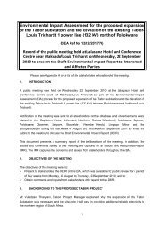
May2010 10P029-023.6 Geology, Soils and Groundwater3.6.1 GeologyAccording to 1in 1000000 "Geological Map of the Republic of South Africa and the Kingdoms ofLesotho andSwaziland 1997" as prepared bythe Council for Geoscience, thesiteis located withintheVryheid Formation of theEcca Series oftheKarooSupergroup. This formation consists principally ofdark-grey shale, which is carbon rich in places (coal), together with interbedded sandstone units. Theshaleis laminated and, on weathering, breaks up into plates and flakes. In the Tutuka area, thePowerStation itself is situated directlyover the Karoo shales, whilst at the landfill site, the Karros hales areoverlainbyalarge dolerite sill of significant thickness.Ageological map showingthe sitelocation is included inFigure3below.Figure 3: Geological Map showing the Tutuka Power Station siteLegend:Jd=DoleritePv=KarooVryheidFormationAccording to Brink (4) , in areas where the Weinert climatic N-value 1 is between 2 and 5, theweathering of the dolerite results intheprimaryminerals decomposing into secondaryminerals of thesmectite group, mainly montmorillonite, occurring in the form of grey to black, highly active clays.1 The N-value is calculatedasN=12xE j /P a , where E j = Evaporation duringJanuaryP a =Annual precipitationPETERLEGG CONSULTING
May2010 11P029-02These clays are best developed in poorly drained areas or flat terrain. The depth of clay is thereforerelated to the topography,being thicker in flat areas and thinner in steeper areas. The Tutuka PowerStation complexand surrounds falls withinthezoneof 2
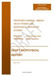
May2010 12P029-02bedrock would provide asafe bearing capacity of about 500 kPa. The weathered rock would beexcavatablebymeans of alarge hydraulic excavator or dozer ripper, without theneedfor blasting.3.7 GroundwaterGHT Consulting Scientists recently carried out ageohydrological investigation of the Tutuka landfilland its surrounds, that included geological mapping, geophysical investigations, installation of threemore monitoring boreholes, ahydocensus, sampling and analysis of surface water and groundwater,and ageohydrological assessment. The results of this investigation are contained in GHT <strong>Report</strong> NoRVN574.1/1025 “Proposed Extension Domestic Waste Site, Tutuka Power Station”, April 2010 (6) .Included hereunder arethe keyfindings forthcoming fromtheGHTgeohydrological report.There are perched and regional aquifer systems associated with the Karoo sediments at the site. Theupper aquifer appears to be perched on an impermeable dolerite sill and has arelatively localizedoccurrence depending on the thickness of the weathered dolerite zone, while the deeper aquifer isrestricted to minor fractures, cracks and joints interfaces within the fresh dolerites. Aquifers withinthese structures are essentiallyunconfinedandperched ontop of theimpermeabledoleritesill. This isconfirmed by the depth to the perched groundwater table beneath the proposed landfill extensionwhich varies fromapproximately3mbgl in the southtoless than1mbgl in thenorth(seeFigure 4).Figure 4: Unsaturated zone /depth to top ofgroundwater table in meters below ground level (5)PETERLEGG CONSULTING
May2010 14P029-02• Additional sampling will also be required in those areas where surface water impoundments areconstructed as part of any waste disposal operations. Should detection monitoring indicate thatwater quality has degraded over time, an increase in the sampling frequency and the number ofparameters tobe determined duringlaboratorytesting will berequired. Specialist geohydrologicaladviceshouldalsobe sought.3.8 DiscussionThe proximity of the existing landfill site to the Tutuka Power Station, Thuthukani Township andNew Denmark Colliery, and its relatively easy access from the main road support its extension anddevelopment as along-term waste disposal facility. By integrating the new waste disposal facilitywith the closure and rehabilitation of the existing landfill represents the best environmentalalternative. As the existing landfill has already impacted on the environment (including thegroundwater), it would be preferable to address the current environmental impacts of the existinglandfill, and extend the landfill, rather than create a new potential environmental impact bydevelopinganewlandfill siteelsewhere.The existing site has infrastructure suchas agatehouse, monitoring boreholes, drains and fencingthatcouldbeused for thenew extended landfill site.Thereis sufficient land available for theproposed extension of thelandfill. The natural topography ofthe area with aslope of about 3% favours the development of alandfill. Due to the dolerite gravelexcavation activities on and around the site, it is not pristine and the development of the landfillextension should not impact significantly on floraand fauna.The shallow excavatable soils on the site mean that soil for waste covering operations will have to beimported from nearby borrow pits. The black clayey colluvial soils are unsuitable for use in thelandfill liner construction, and will have toberemoved and stockpiled for use as cover material inthelandfilling operaions.The residual doleritesoils are gravellyand sandyand thereforealso not suitablefor useintheliner construction, but wouldbeusedto formthebaseof the liner.From a groundwater perspective, the site has a perched aquifer within the fractured/weathereddolerite, and a deeper aquifer beneath the dolerite sill. The aquifer is classified as “low / nosignificance”, and the WASP 2 geohydrological assessment rates the site as “marginal” to “suitable”for the development of awaste disposal facility. The deep soils also favour landfill development,however the fact that the soils are fairly permeable and the area is underlain by significant dolomiticaquifers, means that the landfills will have to be provided with good engineered barrier systems toprotect the groundwater.2 WASP -Waste Aquifer Separation Procedure. Developed by Parsons, R. &Jolly, J. 1994. The developmentof asystematic method for evaluating site suitability for waste disposal based on geohydrological criteria.WRC<strong>Report</strong> No.485/1/94, Pretoria.PETERLEGG CONSULTING
May2010 15P029-024 PRELIMINARY DESIGN OF THE LANDFILL FACILITY4.1 IntroductionThe design presented in this section is apreliminary technical design of the proposed new Tutukalandfill site. It is presented with a view to providing the general layout and content of what isenvisaged at this stage, rather than providing a detailed technical design and constructionspecification. The design is based on the Minimum Requirements for the class of landfill underconsideration (1) ,although in certain instances, the design has been changed from the MinimumRequirements due to site specific conditions. Included in this preliminary design are the proposedlayout, liner details, drainage features, infrastructure and development of the site. Regardingimplementation, it is noted that a full design specification, including construction drawings andschedules ofquantities, wouldhavetobedrawn up onthebasis ofthis designonce approved.The general objective of landfill design is to provide acost-effective, yet environmentally safe andsocially acceptable waste disposal facility. More specifically, the design presented is aimed atminimising the potential for pollution of the environment, particularly the ground water and surfacewater bodies, as well as the surrounding air. Due attention is therefore given to the site specificaspects identified during theon-siteinvestigations.The design makes provision for the phased development of the site, as determined by the wastedisposal need. The intention is to monitor the operation of the facilitycloselyfor the first few years,particularly regarding the size and nature of the waste stream, and operation of the facility. On thebasis of this monitoring, the design may then be modified and further refined for the subsequentphases of thedevelopment.Thelayout and details ofthe design proposed for theTutukaLandfill siteareshown onDrawingNo’s12333/01 to 12333/08includedin Appendix B ofthis report.4.2 Constraints and factors affecting the designTaking into consideration the waste disposal need, the physical conditions of thesite, and discussionswith various <strong>Eskom</strong> and project personnel, there are several factors that affect the design philosophyadopted. Theseare as follows:• The Tutuka landfill facilitydesign needs tocomplywiththe MinimumRequirements for aG:S:B -landfill.• The design of the landfill needs to cater for atotal waste stream of 845 000 tonnes over the 40year site life. With a 20% allowance for soil cover material, a total landfill airspace of1014000 m 3 isrequired.• The northern boundary of the site is defined by the ephemeral stream, whilst the westernboundaryis definedbytheborrow pitwithponded water. The existing landfill defines theeasternboundary of the new landfill. Although the site fence and stormwater drain define the southernPETERLEGG CONSULTING
May2010 16P029-02boundary of the site, it is possible to move this boundary southwards to achieve the requiredairspace.• The soils on the site are not suitable for use in the landfill liner construction. The liner design isthereforebased onageocompositelandfill liner.• The existing landfill has impacted negativelyon the groundwater environment and must thereforebeclosed and capped without delay.• The design of new landfill should be integrated with the closure and capping of the existinglandfill interms of liner anddrainage.• The design must make provision for the sequential phased development of the landfill, such thatleachateflows from thelowest point ofthelandfill cell candischargeintotheleachatepond undergravity.4.3 General site layoutBased on the aforementioned constraints and factors, the overall layout of the initial phase of theTutuka landfill facility has been developed as shown on the attached drawings in Appendix B. Thearrangement of the various facilities and the sequence of development have been determinedaccordingtotopography, drainagerequirements,geologyand distribution ofsoils over the site, accesstothevarious portions ofthe site,andthepossibleimpacts on surrounding landusers.Initially astrip of land adjacent to the western toe of the existing landfill is to be developed togetherwith the shaping and capping of the existing landfill as indicated on Drawing No 12333/05. This area(0.68 ha) is still within the originallypermitted footprint of thelandfill site and can proceed under theexisting landfill permit. Thereafter the remainder of the area (1.77 ha) on the west of the existinglandfill is to be developed up to the borrow pit as indicated on Drawing No 12333/03. Once thislandfill footprint (including the existing landfill) has filled with waste up to its maximum designheight, thearea tothesouth ofthe sitewouldbedevelopedas shown onDrawingNo12333/07 togivethe1million m 3 oftotal landfill airspace required for the40 years of sitelife. Thetotal final footprintarea wouldbeapproximately8.54 ha.The entrance tothe sitewouldremaininits current positionat the southwestern corner of theexistinglandfill for the Phase 1landfill operation. The existing gravel access road off the Tutuka PowerStation road would continue to be used for waste deliveries to the site. The existing gate house at theentrance wouldalso continuetobeused forPhase1operations. OncethePhase2area is developedonthe south side of the existing landfill, the southern fence, site entrance and gate house would have toberelocatedfurther southon theaccess road.The Phase1landfill cells are to be developed adjacent to the western side of the existing landfill withthe contaminated water and leachate ponds located downslope to the north of the landfill to facilitategravitydrainageof contaminatedrun-offandleachate.PETERLEGG CONSULTING
May2010 17P029-02The landfill cells are to be developed generally according to the footprint shapes shown on thedrawings. The initial development of the strip alongside the western toe of the existing landfill andthe shaping of the surface of the existing landfill up to its maximum permitted height of 5mabovenatural groundlevel wouldgiveapproximately4years of operational life.Once the new landfill site licence is obtained the remainder of Phase 1would be developed andlandfilling would takeplaceup toaheight of30 mabovenatural ground level. Development sequencewould be from south to north, starting at the higher elevation to enable gravity drainage of leachateand contaminated water away from the waste body. Astarter berm is to be constructed around theperimeterofthelandfill bymeans of acut-to-fill operation.At thelower end ofthe site on the northern side, the contaminated water andleachate ponds wouldbeconstructed and lined to the Minimum Requirements standards. Provision is to be made at the pondsto extract excess leachate and water either for disposal at the nearby sewage works or for sprayingover the landfill for dust control. This would facilitate reduction of the contaminated water andleachate through evaporation of the water component whilst retaining the contaminants within thelinedlandfill.Aring road would be constructed around the perimeter of the site, as well as storm water drains todivert cleanup-sloperun-offawayfromthefacility.4.4 Services and infrastructure4.4.1 Access and RoadsAccess to the site is directly from the existing Tutuka Power Station eastern access road. The road tothelandfill sitefromthis roadis agravelroad which will havetobemaintained regularlyaccordingtoweather and traffic conditions. Agravel ring road is to be constructed around the facilityto allow formaintenanceand monitoring, as wellas toformafirebreak.Incoming vehicles would be checked at the gatehouse for the type of waste being delivered. Fromthere, the vehicles wouldbedirected toactivetippingarea onthelandfill.4.4.2 WeighbridgeDue to the small quantities of waste expected, it does not justify the installation of aweighbridge. Inexceptional circumstances where vehicle weighing is necessary, this can be arranged at the PowerStation.4.4.3 LaboratoryFor asmall general wastelandfill, alaboratoryis not required on site. Water qualityanalyses are tobeconductedat commercial laboratories or at thePowerStationlaboratory.PETERLEGG CONSULTING
May2010 18P029-024.4.4 FencingThe entire perimeter of the site is to be fenced with a1.8 mhigh razor mesh securityfence to preventunauthorised access. Lockable vehicle access gates are to be provided at the entrance to the site,which shouldalso bemanned24 hours per daybyasecurityguard.4.4.5 WaterFor the small size of operation and small number of site personnel, there is no need to pipe potablewater to the site. Potablewater canbebrought tothe sitein containers for drinkingpurposes.For dust control purposes on the landfill, water from the contaminated water pond is to be usedhowever, if this is insufficient, additional water from the nearby gravel borrow pits will have to beused.4.4.6 ElectricityThere is no need for electrical power at the site. Lighting is not required as the site is only operatedduringdaylight hours.4.4.7 Staff facilitiesThe only building required on the site for the size of the current operation is the existing gatehouse,which has atoilet for the use of the few site staff. When the site entrance is moved to accommodatethe southern extension of the landfill, the new gate house should belarger to include amess room forthesite staff.4.4.8 Plant maintenance facilitiesDue to the landfill site’s close proximityto the Tutuka Power Station, there is no need to establish aplant and equipment maintenance facility on thesite, as theplant and equipment would be sent to theStationworkshops for maintenance.4.5 Landfill design4.5.1 <strong>Design</strong> approachAs stated in Section 2, the Tutuka landfill site has been classified as aG:S:B - landfill. The MinimumRequirements for this class of landfill calls for onlyarecompacted base preparation layer beneath thelandfill rather than aproper liner, and no leachate management system. However, based on the factthat the existing landfill has already impacted on the groundwater environment and that thefractured/weathered dolerite is highly permeable, it is believed that an engineered landfill liner isrequiredat the site.PETERLEGG CONSULTING
May2010 20P029-02The area is to be stripped of black clayand a1.5 mhigh starter berm is to be constructed around theperimeter of the new landfill. The landfill liner is to be constructed as detailed, and a“herring-bone”system of perforated HDPE leachate collector pipes installed diagonally down the slope, to connectinto the leachate pipes beneath the initial development area. Acontaminated water drain lined withgeocells is to be constructed along the outside of the landfill toe, to drain into the contaminated waterpondtothe north ofthe site.The existing upslope stormwater cut-off drain is to be extended in awesterly direction to drain intothewestern borrow pit water body.Bylandfilling this entirePhase 1area with waste up to the raised levels of the existing landfill, it willgive an airspace of approximately 86 500 m 3 ,which would give an operational site life of about7years. If the landfill is then taken up to its maximum practicable height of approximately 30 mabove natural ground level, it will give an airspace of approximately 454 000 m 3 ,which would givean operational sitelifeofabout 25 years4.5.4 Development planThe aim of the Development Plan is to develop the landfill from its initial constructed state, to itsproposed final landform.Landfillingis tocommence on theexistinglandfill toachievetherequired cross falls for drainage, andintheinitial development area at the higher endofthe cell, andis to proceed downslope in anortherlydirection. Initially,apioneering layer of waste at least 600mm thick is to be placed over the liner bymeans of end tippingand spreadingtoprotect theinstalledliner.The working surface of the landfill is to be sloped towards the leachate collector drains at the lowerend of the cell. Landfillingis tobetaken up to maximumpracticableheight (approximately5mabovenatural ground level) before moving downslope to the next deposition area. The outer slopes of thelandfill aretobetaken up at a slopeof 1V:3H.Once the Phase 1 area has been developed, landfilling can be taken up to final height ofapproximately 30 mabove natural ground level. Once this area has been landfilled with waste, theoperation would moveintothesouthern extensionarea.As eachsectionof the landfill cell is completedto final height, theouter slopes of thelandfill areto begraded and final cover applied on an ongoing basis. This will help to minimise leachate generationand will alsomakethelandfill moreaestheticallypleasing.Drawing No 12333/07 shows the sequential development plan for the various stages of developmentfrom theinitial development throughtothe final landformafter 40 years.PETERLEGG CONSULTING
May2010 21P029-024.6 Leachate and drainage managementThe drainagesystems normallyassociatedwithalandfill siteaddress threecomponents:• Uncontaminatedupsloperun-off• Contaminated run-off fromthelandfill itself• Highlycontaminatedleachate generatedwithinthelandfillAll upslope run-off water must be diverted away from the waste, to prevent water contamination andminimise leachate generation. Surface run-off from uncovered waste on the landfill and wastehandling areas is considered to be potentially contaminated, and should not enter natural drainagecourses without prior treatment or sufficient dilution. Highly contaminated leachateshould similarlynot enter thenatural waterregimewithout prior treatment or purification.The different drainage streams arediscussed separately below.4.6.1 Upslope storm water drainageUncontaminated upsloperun-offis tobeprevented from enteringthelandfill facilityareabymeans ofadiversion drain along the higher southern side of the landfill. The existing drain will have to beextended in awesterly direction past the Phase 1landfill area. When the landfill development movesintothesouthern extensionarea, anewupslopedrainwill havetobe constructed.In addition, due to the presence of the perched aquifer within the fractured/weather dolerite, a“findrain” is to be constructed upslope of the landfill site to intercept and divert groundwater seepageawayfrom the wastebody.This “fin drain” would comprise of aperforated HDPE pipewith ageonetvertical fin, all wrapped in ageotextile, set in atrench through the fractured/weathered dolerite, andbackfilled with granular soil (dolerite gravel). The “fin-drain” would daylight on either side of thelandfill. In addition, the perimeter road around the landfill will also act as adrainage diversion berm.At the side of the landfill, the upslope cut-off drains would discharge into the open fields or into theadjacent water bodies. The drains are to be sized to handle peak flows from the 1 in 50 yearrecurrence interval design storm.Thelayout anddetails ofthe storm water drainagesystemareshown ontheattached drawings.4.6.2 Contaminated surface run-offPotentially contaminated run-off from the outer surfaces of the waste body and site roads is to bedirected towards an open V-drain along the outer toe of the starter berm. This contaminated waterdrain would discharge into the contaminated water pond located next to the north of the site. Theworking surface of the landfill is toslope towards the outer berms so that water drains away fromtheworking face towards thetoe drains. As portions of thelandfill reach final height and final cover hasPETERLEGG CONSULTING
May2010 22P029-02been applied, run-off from these areas would be considered as uncontaminated, and the toe drainwouldthenbedirected to linkup withthe clean storm water system.The contaminated water pond has been sized to contain the runoff from half of the exposed wastebodyfor the1in 50 year recurrence interval 24 hour duration storm. The run-off pond has been sizedat 1880 m 3 ,plus a500mmfreeboard. The contaminated water pondis tobe50 mx25 mx3mdeep,with ageocell lined spillway to discharge overflow water during extreme rainfall events. The linerdesign for the contaminated water pond is discussed in Section 4.7, and the details of the pond areshownonDrawingNo12333/08.4.6.3 Leachate ManagementThethreemain components ofaleachatemanagement system includethefollowing:• Theliner beneaththelandfill toprevent infiltration into theground water.• The collection system totransferleachatetothetreatment system.• Theleachatetreatment systemtoprevent surfacewaterpollution byleachate.Anyleachate emanating fromthe wasteinthelandfill wouldappear inthe 150 mmthick granular soillayer overlying the composite liner and would flow downslope beneath the landfill towards theleachate collector drains. These drains would consist of 110 mm diameter perforated HDPE pipesplaced withinazoneof38 mmaggregateapproximately1mwide.These primary leachate collectors would discharge into a315 mm diameter main leachate gravitydrain running along the centre of the landfill, to discharge into the leachate sump located to the northof the facility. Manholes are to be provided at the top and bottom of this leachate main drain forinspection and maintenance purposes. Manholes on all leachate drains are to have vented manholecovers toprevent thebuild up oflandfill gas inthese manholes.Leachate emanating from the landfill is to be contained in an HDPE sump, located to the north of thelandfill. Leachate fromthe leachatesump is to be removed bytanker and taken tothe nearest sewagetreatment works for treatment. The leachate sump will have amanhole to facilitate leachate removalandanoverflowinto thecontaminatedwater pond.Since the landfill is located within a water deficit area with anegative climatic water balance,significant leachate generation is not expected. However, during the earlystages of waste despositionover the exposedliner, therewould besignificant run-off that will enter theleachatesystem. This runoffwouldtend tobeaveryweak contaminated water rather than actual leachate, sothereshouldbenoproblem allowing it to overflow from the leachate sump into the contaminated water pond. Theleachate sump is to consist of a“Weholite” HDPE pipe 1.8 mdia by 6mlong laid horizontally andwith blank flanges weldedtoboth ends. Theleachateinlet and outlet pipes will be weldedthroughtheend flanges, and avertical manholeis to be welded into the top of the sump. The effective volume ofPETERLEGG CONSULTING
May2010 23P029-02the leachate sump would be approximately 12 m 3 .The details of the leachate sump are shown onDrawing No12333/08.4.7 Liner designsTheliner designs for thelandfill andthecontaminated waterpond havebeen developedin accordancewith the Minimum Requirements, although various modifications and improvements havebeen madeto address site specific conditions. The various liner designs are shown on Drawing Nos 12333/04,12333/06 and12333/08.4.7.1 Landfill liner (G:S:B - )In terms of the Minimum Requirements, an G:S:B - landfill liner would normally comprise of only arecompacted base preparation layer of in-situ soil. However, in view of the fact that the in-situdolerite soils and fractured dolerite are highlypermeable, and because the existing landfill, that doesnot have abottom liner, has contaminated the groundwater, an upgrade liner is proposed for thelandfill extension. As there is no suitable clay in the area for the construction of acompacted clayliner, ageosynthetic clayliner (GCL) is proposed. The liner proposed for the landfill extension wouldthereforecompriseofthe followingcomponents, working fromthetop downwards:• Leachate detection and collection drains at 25 mcentres, comprising of 110 mm dia perforatedHDPE pipes, set in1mwidestrips of 38 mmaggregate 300 mmdeep.• 150 mmlayer of granular soil (blocky,“sugar” dolerite).• 150 mmlayer of fine soil.• Geosynthetic clayliner (GCL) (3 600 kg/m 2 ).• 150 mmbasepreparation layer (recompactionofin-situ sandysoil).4.7.2 Existing landfill “Piggy-back” linerAs stated earlier, the top of the existing landfill is to be brought up to the required levels to achievegravitydrainageinanorth westerlydirection bymeans of landfillingfurther waste ontop. Thereafter,the surface is to be compacted and shaped to receive the “Piggy-back” liner system over the existinglandfill surface, comprising of the following components,working fromthe top downwards:• Leachate detection and collection drains at 25 mcentres, comprising of 110 mm dia perforatedHDPE pipes, set in1mwidestrips of 38 mmaggregate 300 mmdeep.• 150 mmlayer of granular soil (blocky,“sugar” dolerite).• 150 mmlayer of fine soil.• Geosynthetic clayliner (GCL) (3 600 kg/m 2 ).• 150 mmlayer of fine soil.PETERLEGG CONSULTING
May2010 24P029-02• Geogrid (RockGrid PC50/50 or equivalent) to address localised differential settlement of thewaste.• 150 mmbaselevelling layer ofdolerite soil on compacted waste.4.7.3 Contaminated water pond liner (G:S:B - )Theliner design for thecontaminated water pond wouldbe similar tothelandfillliner, except that theleachate drainage layer would not be required. The liner layers on the base and walls of the pondwouldthereforecompriseof the followingcomponents, working from thetop downwards:• 500 mmsoil protection and confininglayer• Geosynthetic clayliner (GCL) (3 600 kg/m 2 ).• 150 mmbasepreparation layer (recompaction of in-situ siltysoil)4.7.4 Existing landfill final coverThe outer slopes of the existing landfill will have to be capped and rehabilitated. As these slopes aresteeper than 1:3 (V:H), it will be necessary to retain the soil on the slopes. The final cover for theeastern and northern slopes of the existing landfill include the following components, working fromthetop downwards:• 200 mmtopsoil withindigenous grass• !50 mmdeep geocells filled with dolerite soil.• Geosynthetic clayliner (GCL) (3 600 kg/m 2 ).• 150 mmbasepreparation andlevellinglayer ofsoil4.7.5 Construction Quality AssuranceThe main risk to the performance of ageosynthetic liner system is mechanical/physical damage,during and after installation. For this reason, it is imperativethat the liner is supplied and installed byacompetent and reputablecontractor, and in accordance witha strict qualityassuranceprogramme. Inparticular, extreme care must betaken whenplacing the cover soil over theinstalledGCL so as not todamagetheliner. Strict supervisionis required.4.8 Landfill Gas ManagementOnaccount of the organic content of the general waste it is highlylikely that thelandfill will producelandfill gas. However, due to the remote location of the landfill away from any human development,as well as the small size of the landfill operation, it is proposed at this stage that a formal gasmanagement system at the site is not necessary. This is in accordance with the MinimumRequirements. Due to the limited compaction applied by the site TLB (tractor-loader-backhoe) andPETERLEGG CONSULTING
May2010 25P029-02the fact that cover material is not always applied on adaily basis, it is accepted that landfill gasgenerated will diffuseintothe atmospherewithout creating anyhealthand safetyrisks.If however it is determined at alater stage that significant landfill gas is being generated causingodour problems and explosion hazard risks in confined structures such as manholes, etc, aformal gasmanagement plan should be developed. This could include asimple passive gas venting systemcomprisingrock filled gabion chimneys constructed within the wastebodyand extending upwards asthelandfill rises. Each chimney is to be wrapped in geotextile filter fabric and a small mound of soilis tobe placed aroundit to prevent ingress of surfacerun-off, andto stabilise the chimney. These gaschimneys aretobe spacedat approximately1per 0,1 hectare.When the final capping is applied to the landfill at various stages of completion, appropriate cappingstructures would be constructed over the gas chimneys to enable passive venting to continue.Although active gas extraction and flaring of landfill gas would bepreferable to passive venting, it isnot consideredtobeappropriateor cost effectivefor suchasmall landfilllocated inaremote area.Notwithstanding the above, the gas management system at the site must incorporateagas monitoringsystem, includingthe following:• Monitoring of landfill gas concentrations on aregular basis on the landfill during operation andafter closure.• Regular monitoring of safe practices to avoid hazardous concentrations of gases at temporary orpermanent workingareas of thesite.4.9 Closure andEnd-useThe objectives of theend-use designof thelandfill areas follows:• To create an aesthetically acceptable landform with gentle slopes (not exceeding 1:3) that, as faras possible, blends in withthe surroundingterrain.• To maximisethelandfill airspace available for wastedisposal and hencethesitelife.4.9.1 Final landform and end-useAt this stage, the proposed final shape of the landfills would be determined according to thesurrounding terrain, and to maximise the airspace from the available footprint. It would also bedesigned to meet drainage and end-use requirements. It is recommended that the end-use of thelandfill be consideredas restricted open space, on account of the waste disposed onit. Other forms ofdevelopment could also be considered. The end-use of the siteshould, however, be discussed withallstakeholders to ensurethat therehabilitated siteis acceptabletothem.PETERLEGG CONSULTING
May2010 26P029-02Based on the surrounding topography and land use, the maximum height of the landfills would beabout 30 mabove the original natural ground level. The upper surfaces of the landfill must havegeneral slopes ofat least 1:50 topromote rapid drainageofthelandfill surface.4.9.2 Closure andrehabilitationAs the different sections of the landfill are completed to final height, they are to be appropriatelyshaped, graded and capped in accordance with the Minimum Requirements. As the new landfillwould have abottom liner, the final capping for aG:S:B - landfill would only need to include a200 mmlayer of topsoil, appropriatelygrassed.Vegetation of completed areas is to commence as soon as possible after capping. Indigenous shrubscould be planted around the site for screening purposes, as well as in any areas where the substratewill support growth. Over the rest of the site, grass is to be established using indigenous grass types.Theintention is toimplement what is knownas "therising green wall effect" byprogressivelygradingand vegetating thesideberms andthen workingbehind them.Provided the vegetation is always maintained during operation, there should be no need for laterrehabilitation. After closure, ongoing maintenance of the landfill capping and vegetation will berequired.4.10 DiscussionIn formulating the preliminary design for theTutuka landfill site, every effort has been made to meetthe objectives of landfill design, i.e. to provide a cost effective, environmentally and sociallyacceptable facility. In addition, the requirements of the Minimum Requirements have been followedandthe “PrecautionaryPrinciple” has beenimplemented throughout.Whilst thedesign meets thewaste disposal needs of thecurrent users of theTutuka landfill site, it alsoaddresses all the site specific factors and constraints identified during the site investigations. Thevarious issues and impacts associated withlandfilling operations on afacility of this nature have alsobeen considered in thedesign.PETERLEGG CONSULTING
May2010 27P029-025 PRELIMINARY OPERATING PLAN5.1 IntroductionThis section provides apreliminaryOperating Plan, in terms of which the Tutuka landfill facility willbeoperated. The objective of theOperatingPlanis to ensurethatall wasteis disposed of in amannerthat is environmentally acceptable. In this way,the negative impacts normally associated with wastedisposal operations would be avoided or minimized. This implies that the operation must conformtothe“Minimum Requirements for WasteDisposal byLandfill” (1) and the “MinimumRequirements forMonitoring at WasteManagement Facilities” (2) associated withthe siteclassification.The Operating Plan is site specific and describes the way in which the facility should be operated,addressing aspects suchas access, controls, drainage, landfilling, etc.In order to ensure that the operation complies with the aforementioned requirements, resources suchas funds, suitable facilities, equipment and staff, includinga ResponsiblePerson, arerequired.It is noted that this is apreliminaryOperating Plan and that it is to besuperseded byacomprehensiveOperatingandMaintenanceManual tobepreparedas part ofthe detailedengineeringphase.5.2 AccessVehicle access must always be limited to asingle entrance, to facilitate control. During hours ofoperation, this entrance must be mannedandit must belocked whenthe facilityis not in operation, toprevent unauthorised entry. Anoticeboard must beerected at theentrance, statingthe name, address,and telephone number of the operator, the hours of operation and an emergency telephone number.Suitable signs must alsobeerectedon-site, todirect drivers andto control speed.Road access to the landfill working face must be maintained at all times in amanner suitable toaccommodate vehicles normallyexpected to utilisethe facility. All on-site roads must beso surfacedand maintained as to ensurethat waste can reach theworking face with minimuminconvenienceinallweather. Roads must alsoberegularlygradedand wettedto control dust, whennecessary.5.3 Control5.3.1 Waste reclaimersInformal waste reclamation (or scavenging) is afeature of many landfills in developing countries.Such reclamation has security and public health risks associated with it, and for this reason it isrecommended that it be strictlyforbidden at thefacility.PETERLEGG CONSULTING
May2010 28P029-025.3.2 Waste acceptancePrior to waste being accepted at the gate, it must be verified as general waste by visual inspection bythe gatekeeper and confirmed with the transporter. Industrial wastes, liquids, sludges, and drummedwastes shouldberegarded as potentiallyhazardous. In theevent ofsuch wastes beingintercepted, thesiteoperator should beinformed and hazardous waste must not be accepted at thelandfill site. It mustbe directed back to the generator for subsequent disposal at apermitted hazardous waste facility, asappropriate. The operator at the landfill working face must also ensure that no hazardous wastes aredisposed ofinthis area.At all times the precautionary principle should apply, i.e. any consignment of waste suspected ofbeing hazardous, must be considered hazardous unless proven otherwise by means of laboratorytesting.Nohazardous or medical waste maybeacceptedat thelandfill site.5.3.3 RecordsAccurate and comprehensive records must be kept of all waste entering the site. Waste must becategorised by the number of loads, defined by quantity, type and origin. Records must be kept onboth adailyand acumulativebasis. Oneor acombination of the following systems couldbe used forrecordkeeping:• Asimple record system where entries are made byhand onto pre-prepared forms in such awaythat it can be collated manually and later introduced into acomputer. Office personal computersinclusiveofappropriate softwareshouldbeprovided.• Amass measuringunit with handcapturing ofdata formanual orcomputerised collation.In addition, meteorological records shouldbe kept, includingrainfall, evaporation, wind, etc.5.3.4 AuditingRegular auditing of the site should be carried out during the operation, to ensure that the site designand the development plans are implemented, and that an acceptablestandard is adhered to. The auditteam should typically consist of the site operator, representatives from Tutuka Power Station and theappropriate environmental authorities. It may also be appropriate to include representatives of theinterested and affected public on the audit team. The frequency of theaudits must beagreed to byalltheparties concerned, but intervals shouldnot exceed 12months.5.3.5 Landfill gas monitoringDuring routine audits, detection for landfill gas at the landfill should be carried out to determine theneed for gas management.PETERLEGG CONSULTING
May2010 29P029-025.4 Water Quality MonitoringTo ensure adequate environmental protection, along term water quality monitoring programme forboth groundwater and surface water is required at the site. This would involve background analyses,routinedetection monitoring, investigativemonitoringand post closure monitoring.The objectives of thewater qualitymonitoring systemare:• To indicateanyescapeofleachateintothe environment andtoquantifyits effect• To serve as an early warning system so that pollution problems that arise can be timeouslyidentifiedandrectified.The water quality monitoring system therefore includes the monitoring of surface water bodies,groundwater, leachate and contaminated water in the pond. Water and leachate samples are to becollected and analysed for the water quality parameters as required in the “Minimum Requirementsfor Monitoring at Waste Management Facilities” (2) . <strong>Eskom</strong> has appointed specialist groundwaterconsultants GHT Consulting Scientists for all the water quality monitoring on and around the TutukaPower Station complex. The details of the water quality monitoring system for the landfill wouldincludethefollowing:5.4.1 Background analysesGroundwater samples should be taken from all the monitoring wells installed over the life of thelandfill. These include one upstream borehole (DMB35) and 6downstream boreholes (DMB33,DMB34, DMB86, DMB87,DMB88, DMB89). These samples must beanalysedto obtain backgroundwater quality data before the construction of the new extended landfill. Acomplete backgroundanalysis ofthegroundwater shouldbetaken beforetheconstructionofthelandfill extension.5.4.2 Surface waterThere are three surface water bodies in the vicinity of the site. The monitoring points are in the twodams on the ephemeral stream both upstream and downstream of the landfill site, and the pondedwater in the borrow pit to the west of the site. Samples should be taken and analysed four times peryear.5.4.3 Ground waterThe monitoring wells installed as part of the plant monitoring programme are to be used for groundwater monitoring. Ground wateris tobesampledand analysedat three monthlyintervals.PETERLEGG CONSULTING
May2010 30P029-025.4.4 Leachate and contaminated waterLeachate in the leachate sump and the existing leachate detection well, as well as water in thecontaminated water pond, is to be sampled and analysed for control purposes. Samples are to betaken andanalysedat threemonthlyintervals together withthesurfaceandground water monitoring.5.4.5 <strong>Report</strong>ingThe analyses of all samples should be interpreted to identify any trends or deterioration of waterquality that could result from the operations of the waste management facility. The water qualitymonitoring report should be submitted to Tutuka Power Station environmental management and therelevant regulatoryauthorities.5.5 RecyclingIf deemed feasible, controlled salvaging may be implemented at the landfill working face, providedthat it is carried out in asafe and hygienic manner, and provided that it does not create alitterproblem.5.6 Landfilling operationIncoming general waste can be discharged directly into the working cell of the landfill. The landfillmust, as far as possible, be operated in accordance with the following sanitary landfill operatingprinciples:• Wastemust be spreadand compactedincells, and• Coveredat the endof each day’s operation.5.6.1 Cell OperationThe landfill operation is based on the construction of aseries of cells, which are prepared to receivethe waste. The basic landfill unit is thus acell of compacted solid waste which, when completed atthe end of each day, is entirely contained bycover material. The sides may be formed by1mhighsoil or rubble berms, or sloped waste covered by daily cover. The width of the cell is determined bythe working face, which is determined by the manoeuvring needs of the vehicles depositing waste.This must be sufficientlywideto avoid traffic congestion, but not so wide that waste is unnecessarilyleft exposed. There must always be sufficient cell capacity on site to accommodate at least oneweek's waste."End tipping", where waste is pushed over the edge of an advancing face, is not permitted. Wastemust be deposited at the bottom of the working face, spread, and worked up a1in 3slope up theworking face within the cell. Compaction is best achieved if the waste is spread in layers notexceeding 500mm thick (uncompacted) and passed over aminimum of five times by the landfillcompactor or loader.PETERLEGG CONSULTING
May2010 31P029-025.6.2 CoverThe sanitary landfill definition specifies daily or more frequent cover. The material to be used forcover will be excavated and loaded up from the nearby doleriteborrow pit, but mayalso be importedsoil, builders' rubble, or other approved covering. In all cases, astrategic stockpile of cover, enoughfor at least three days, should be maintained close to the working face for use in emergencies.Suitable equipment and resources must also be available to ensure that there is sufficient covermaterial, so that no area is left uncovered at the end of the day's operation. In order to facilitate this,incoming cover should be deposited along the top of the cell, either on the completed portion of thecurrent cell, or ontheadjacent cell.Putrescible waste, such as food waste or dead animals, shouldbe deposited and covered immediatelywith soil. Alternatively, such waste can be deposited at the base of the working face and coveredimmediatelywithother waste.Daily or periodic cover must be sufficient to isolate the waste from the environment. Aminimumthickness of 100 mm of compacted soil or other appropriateinert material is usuallyrequired. If thereis aproblemwith odours fromthelandfill, thethickness ofthe cover might havetobeincreased. Finalcover must beas thickas possible, using constructionrubbleand gravel.5.6.3 Wet weather cellAn easily accessible wet weather cell must be constructed close to the haul road, for use underabnormally wet weather conditions. The wet weather cell must have sufficient capacity toaccommodate two weeks’ waste. The wet weather cell should be constructed in the same manner asthe standard cell, except that it should have awell-drained base using construction rubble or similarmaterial to ensure vehicle access in wet weather. As far as possible, the wet weather cell should beoperatedinthesame manner as the standardcell.5.7 Landfill DrainageThe underlyingprinciples oflandfill sitedrainageareas follows:• All run-off water must be diverted away from the waste, to prevent water contamination andminimiseleachategeneration.• Where contaminated water or leachate does arise on site, it must be managed and kept out of theenvironment.• Clean, uncontaminated run-off water must not be permittedtomixwith and increase the volumesofcontaminated water.Adrainage system which achieves the above is presented in the design section of this report. Onceconstructed, this system must be maintained. As part of the leachate management procedure, thePETERLEGG CONSULTING
May2010 32P029-02quality of both leachate and contaminated water should be monitored on aregular basis to determinethesuitabilityfor dischargeto thesewagetreatment plant or other disposal methods.Detailed on-site drainage at the working faces must continuously be adapted and developed as thelandfill develops. Detailedon-site drainagemust alsobeproperlymanagedas follows:• All clean, uncontaminated water must be allowed to flow off the site into the natural drainagesystem,under controlled conditions.• The base of the site at the working face must be so graded that water drains away from thedepositedwaste.• All water contaminated by contact with waste must be contained and discharged into the run-offwaterpond.• All leachate collectedmust bedischargedintotheleachatesump.• All temporarily and finally covered areas must be graded and maintained to promote run-off andeliminateponding or standing water.5.8 ResourcesSuitable equipment and resources must be made available to ensure that the waste is properlyspread,compacted and covered at the end of each day's operation. The equipment must therefore have theversatilityto executeseveral functions, including gradingand shaping, as well as mixingand blendingof wastes. Backup plant must alsobeavailablein caseof breakdowns.5.8.1 PlantNormally, apurpose built landfill compactor would be recommended as the main item of plant,together with other items of plant. However, in this case asmall tracked loader or TLB with solidtyres would berecommended as the mainitem of plant, as it is considered to provide more flexibilityfor cover operations. In addition, thereshouldbeaccess toa secondTLB as backup.Other items of plant wouldinclude asmall water tanker or trailer for dust control, and atipper truckfor handling cover material.5.8.2 StaffingFor theoperationofthefacility, thefollowing staff compliment is recommendedto ensurethat thesiteis operatedto ahighstandard:• OneSiteSupervisor. This person is responsible for the proper operation of the entire facility.Thesitesupervisor must ensure that all thefacilityrequirements arefullycomplied with.PETERLEGG CONSULTING
May2010 33P029-02• OnePlant operator. This personis responsible for operatingthewastedisposal area and hence theTLB. Theplant operator will alsoberesponsiblefor operatingthetractor-trailer, tractor-water cartand other landfill equipment.• One gate controller to control access and record waste loads during operating hours. The gatecontroller canalsoact as the spotter todirect vehicles tothecorrect tipping area.• Onelitterpicker and general worker.• Onesecurityguardfor general sitesecurity.5.9 Control of NuisancesIn order to control nuisances, sanitary landfilling principles must be used. This is amethod ofdisposingof waste onland without causing nuisances or hazards topublichealth or safety, byutilisingtheprinciples of engineering to compact the wasteand to coverit with alayer ofsoil at the conclusionof each day's operation, or at more frequent intervals as maybenecessary.To ensure that the waste management facility is operated to these standards, environmentalmanagement and control of the operation are essential. Some of the common short-term problemsassociated with landfill operations andtheir possible solutions, arelistedbelow:• Dust: On-site roads should be wetted in hot dry weather to reduce dust from traffic whennecessary.• Odours: Odours are generated as aresult of biological degradation of waste. Daily covering ofthe waste and the maintenance of this cover should ensure that odours from both "fresh" anddecomposed wastedo not becomeaproblem. Putrescible waste shouldbe coveredimmediately.• Fires: Burning of waste is prohibited. Compaction and covering of waste minimises the fire riskbyminimising oxygen and exposure. Where fires do occur, theburning waste should be exposed,spread, and smothered with cover material. Onnoaccount is water tobeadded.• Flies and Rodents: Immediate compaction and daily covering of waste reduces thelikelihood ofthis becoming anuisance. Nevertheless, flies are commonlyassociated with landfill sites and flytraps shouldbe usedto control this problem.• Litter: Compaction and covering of the waste reduces therisk of windblownlitter. Litter screenscanalso beusedtocontrol litter. All windblownlitter should becollected fromaroundthe siteonaregular basis.• Aesthetics: The rehabilitation of completed areas would improve the general appearance of thesite.• Health: Medical waste should not be accepted at the landfill. Other putrescible waste should becoveredimmediately.• Drainage: Waste deposition should be such that it ensures that water runs away from the wastebody,anddoes not formponds ontop of thewaste, from whereit might infiltrate.PETERLEGG CONSULTING
May2010 34P029-025.10 Development PlanThe aim of theDevelopment Plan is to develop thelandfill site from its constructed stateas indicatedon the drawings to the intended final landform (see Drawing No 12333/07). The intention is thatcontrolled development should take place, and that all the operating principles in the precedingsections shouldbeimplemented and controlledthrough siteaudits.The first aspect of the Development Plan is the site preparation. This includes fencing, gate control,site clearance, and the preparation of the first phase for waste deposition (i.e., cover excavation,stockpiling, and construction of berms). In the landfill, apioneering layer of waste at least 600 mmthick is to be placed over the constructed liner before any landfilling is to proceed. This is to becarried out by end-tipping and spreading the waste ahead of the equipment, so as to create abed ofwaste on which to operate, and soprotect theinstalledliner systems.The detaileddevelopment ofthelandfill shouldfollow thedevelopment plan, andadaptedif necessarybased on sitespecific circumstances as theyarise.5.11 RehabilitationAll final levels and slopes must beinconformance with thelandfill design and the end-use plan, withslopes not steeper than 1in 3. Once the final level is achieved, the area must be capped/covered withthe final cover in accordance with the plan. Rehabilitation is to commence as soon as practicallypossible after the final level has been reached in order to rehabilitate on an ongoing basis and toprevent windexposure of waste.5.12 Closure planAs thelandfill approaches final levels, moreaccuratelevels will havetobe surveyed to ensurethat thefinal gradients anddrainageare correct.Immediately on completion of an area, final cover must be applied. Completed areas also requireongoing maintenance, including the repair of cracks and areas exposedbywind, and the filling of anysettlement depressions. The rehabilitated areas should be controlled by ongoing monitoring after siteclosure, which shouldbecomplemented bywater pollution monitoring.5.13 DiscussionThe preliminary Operating Plan outlined above should, if properly implemented, prevent thepossiblenegative impacts normally associated with waste disposal from becoming a nuisance or anenvironmental threat. It must be stressed, however, that to ensure environmentallyacceptable wastedisposal, the resources outlined in this plan, such as funds, suitable facilities, equipment and staff,must bemadeavailable.PETERLEGG CONSULTING
May2010 35P029-026 CONCLUSIONSBased on the results of the site investigations undertaken and the content of this report, the followingconclusions aredrawnregardingtheproposedTutukalandfill facility.• There is arequirement for asmall sized general waste landfill, classified as G:S:B - ,with anairspaceof approximately1014 000 m 3 for the 40 year designlife.• From a consideration of various alternative candidate landfill sites, it was determined thatintegrating the new waste disposal facility with the closure and rehabilitation of the existinglandfill represents thebest environmental alternative.• As the existing landfill has already impacted on the environment (including the groundwater), itwould be preferable to address the current environmental impacts of the existing landfill, andextend the landfill, rather than create anew potential environmental impact bydeveloping anewlandfill siteelsewhere.• The proximityof the existing landfill site to the Tutuka Power Station, Thuthukani Township andNew Denmark Colliery, and its relatively easy access from the main road support its extensionand development as along-termwastedisposal facility.• The existingsite has infrastructuresuch as agatehouse, monitoringboreholes, drains and fencingthat couldbeused for the new extendedlandfill site.• There is sufficient land available for the proposed extension of the landfill and the naturaltopographyof thearea favours the development of alandfill. Duetothedoleritegravel excavationactivities on and around the site, it is not pristine and the development of the landfill extensionshould not impact significantlyon floraand fauna.• Theshallow excavatable soils onthe sitemeanthat soil for wastecoveringoperations will havetobeimported fromnearbyborrowpits. Theblack clayey colluvial soils areunsuitablefor useinthelandfill liner construction, and will have to be removed. The residual dolerite soils are gravellyand sandyandthereforealso not suitablefor useintheliner construction.• From agroundwater perspective, the site has aperched aquifer within the fractured/weathereddolerite, and adeeper aquifer beneath the dolerite sill. The aquifer is classified as “low /nosignificance”, and thegeohydrological assessment rates the siteas “marginal” to “suitable” for thedevelopment ofawastedisposal facility.• The site designis based ondeveloping thefollowingmainareas of operation, viz:- Extension ofthe existinglandfill tousethe full permitted footprint.- Raising, shapingand cappingthe existinglandfill with aGCL based “piggy-back” liner.- Development of aGCL lined extension of the landfill to the west of the existing landfill,followedbyafurther extension to thesouthtoachievetherequired sitelife.- Constructionof aleachate sumpand contaminated water pond..• Thelandfill isbasedonsanitarylandfilling of general wasteinalinedlandfill cell.PETERLEGG CONSULTING
May2010 36P029-02• In formulating the preliminary design for the Tutuka landfill site, every effort has been made tomeet the objectives oflandfilldesign, i.e. toprovide acost effective, environmentallyand sociallyacceptable facility. In addition, the requirements of the Minimum Requirements have beenfollowedandthe“PrecautionaryPrinciple” has beenimplementedthroughout.• Whilst the design meets the wastedisposal needs of the current users of theTutuka landfill site, italso addresses allthe sitespecificfactors and constraints identifiedduringthe siteinvestigations.7 RECOMMENDATIONSIt is recommendedthat landfill designreport besubmittedin support ofthelandfilllicence applicationtotheregulatoryauthorities.8 REFERENCES1. Department of Water Affairs and Forestry, 1998. Minimum Requirements for Waste Disposalby Landfill. Waste Management Series -Volume 2, Second edition. Department of WaterAffairs and Forestry. CTP BookPrinters, Cape.2. Department of Water Affairs and Forestry, 1998. Minimum Requirements for WaterMonitoring at Waste Management Facilities. Waste Management Series -Volume 2, Secondedition. Department ofWater Affairs and Forestry. CTP BookPrinters, Cape.3. Golder Associates Africa, January 2010. Tutuka Power Station -Classification of New andCurrentTutukaDisposal Site. <strong>Report</strong> No 12330-9390-1, prepared for Zitholele Consulting.4. Brink A.B.A., 1983. Engineering Geology of Southern Africa – Volume 3: The KarooSequence. BuildingPublications.5. Peter Legg Consulting, February2010. Geotechnical Investigation<strong>Report</strong> for theExtension ofthe Tutuka Power Station Landfill Site. <strong>Report</strong> No P029-01, prepared for ZitholeleConsulting.6. GHT Consulting Scientists, April 2010. Proposed Extension Domestic Waste Site, TutukaPower Station. <strong>Report</strong> No RVN574.1/1025, prepared froZitholele Consulting.PETER LEGG CONSULTINGPeterLegg, PrEngPETERLEGG CONSULTING
APPENDIX AWASTEGENERATION AND LANDFILL AIRSPACEREQUIREMENTSPETERLEGG CONSULTING
GrowthRate(%)New PowerDenmark StationColliery CleaningTutuka LandfillSiteWaste Generation andLandfillAirspace RequirementsHorticulturalContractors TutukaniTotalperyear IRD Cummulative Airspacetonne tonne tonne tonne tonne tonne tonne/day tonne m 3 m 33.7 3.7 3.7 3.7 3.7%of total 19% 29% 5% 35% 12% 9100Landfilldensity = 1tonne/m3Airspaceincl cover(20%)2009 1729 2639 455 3185 1092 9100 35 9100 9100 109202010 1793 2737 472 3303 1132 9437 36 18537 18537 222442011 1859 2838 489 3425 1174 9786 38 28323 28323 339872012 1928 2943 507 3552 1218 10148 39 38470 38470 461652013 1999 3052 526 3683 1263 10523 40 48994 48994 587932014 2073 3165 546 3819 1310 10913 42 59907 59907 718882015 2150 3282 566 3961 1358 11317 44 71223 71223 854682016 2230 3403 587 4107 1408 11735 45 82958 82958 995502017 2312 3529 608 4259 1460 12169 47 95128 95128 1141542018 2398 3660 631 4417 1514 12620 49 107748 107748 1292972019 2486 3795 654 4580 1570 13087 50 120834 120834 1450012020 2578 3936 679 4750 1629 13571 52 134405 134405 1612862021 2674 4081 704 4926 1689 14073 54 148478 148478 1781742022 2773 4232 730 5108 1751 14594 56 163072 163072 1956862023 2875 4389 757 5297 1816 15134 58 178206 178206 2138472024 2982 4551 785 5493 1883 15694 60 193899 193899 2326792025 3092 4720 814 5696 1953 16274 63 210173 210173 2522082026 3207 4894 844 5907 2025 16876 65 227050 227050 2724602027 3325 5075 875 6125 2100 17501 67 244551 244551 2934612028 3448 5263 907 6352 2178 18148 70 262699 262699 3152392029 3576 5458 941 6587 2258 18820 72 281519 281519 3378232030 3708 5660 976 6831 2342 19516 75 301035 301035 3612422031 3845 5869 1012 7083 2429 20238 78 321273 321273 3855282032 3988 6086 1049 7345 2518 20987 81 342261 342261 4107132033 4135 6311 1088 7617 2612 21764 84 364024 364024 4368292034 4288 6545 1128 7899 2708 22569 87 386593 386593 4639122035 4447 6787 1170 8191 2808 23404 90 409997 409997 4919962036 4611 7038 1213 8494 2912 24270 93 434267 434267 5211202037 4782 7299 1258 8809 3020 25168 97 459435 459435 5513222038 4959 7569 1305 9135 3132 26099 100 485534 485534 5826412039 5142 7849 1353 9473 3248 27065 104 512599 512599 6151182040 5333 8139 1403 9823 3368 28066 108 540665 540665 6487982041 5530 8440 1455 10187 3493 29105 112 569769 569769 6837232042 5734 8753 1509 10564 3622 30181 116 599951 599951 7199412043 5947 9076 1565 10954 3756 31298 120 631249 631249 7574992044 6167 9412 1623 11360 3895 32456 125 663705 663705 7964462045 6395 9761 1683 11780 4039 33657 129 697362 697362 8368352046 6631 10122 1745 12216 4188 34902 134 732265 732265 8787182047 6877 10496 1810 12668 4343 36194 139 768459 768459 9221502048 7131 10885 1877 13137 4504 37533 144 805992 805992 9671902049 7395 11287 1946 13623 4671 38922 150 844913 844913 1013896MRD(tonne/day)150 SmallPETERLEGG CONSULTING
APPENDIX BDRAWINGSDrawing No Rev Title12333/01 A ExistingSiteSurvey–September 200912333/02 A SiteSurveyshowingTestpit positions12333/03 A Extension of ExistingLandfill –Phase1-General Arrangement12333/04 A Extension of ExistingLandfill –Phase1–Sections and Details12333/05 A InterimLandfill Extension–General Arrangement12333/06 A InterimLandfill Extension–Sections andDetails12333/07 A Extension of ExistingLandfill –Development Plan12333/08 A Extension of ExistingLandfill –LeachateSump and ContaminatedWaterPond–Sections andDetailsPETERLEGG CONSULTING
DATEREVISIONDESCRIPTIONINITSINITS DATECHECKED APPROVEDREFERENCESINFORMATION CONTAINED ON THISDRAWING IS THE COPYRIGHT OFZITHOLELE CONSULTING (PTY).LTD.UNAUTHORISED USE ORREPRODUCTIONOF THIS PLAN EITHERWHOLLY ORINPARTWITHOUT WRITTENPERMISSIONINFRINGES COPYRIGHT.C ZITHOLELE CONSULTING(PTY)LTD.ZitholeleConsulting(Pty)LtdMIDRANDOFFICEThandanani Park, MatukaClose, MidrandPOBox 6002 , HalfwayHouse, 1685SouthAfricaTel:+(27)(0)11254-4800www.zitholele.co.zaFax:+(27)(0)11 315-3284http:\\CLIENTDRAWNDESIGNEDAUTHORISEDDATE DRAWING CHECKDATE DESIGN CHECKDATE SCALEPROJECTDATE DRAWINGTITLEDATEPROJECTNoDRAWING NoREVISION
DATEREVISIONDESCRIPTIONINITSINITS DATECHECKED APPROVEDREFERENCESINFORMATION CONTAINEDONTHISDRAWING IS THE COPYRIGHTOFZITHOLELE CONSULTING (PTY). LTD.UNAUTHORISED USE OR REPRODUCTIONOF THIS PLAN EITHERWHOLLYORINPART WITHOUT WRITTEN PERMISSIONINFRINGES COPYRIGHT.C ZITHOLELE CONSULTING (PTY)LTD.ZitholeleConsulting (Pty) LtdMIDRAND OFFICEThandanani Park, MatukaClose, MidrandPOBox 6002,HalfwayHouse,1685SouthAfricaTel: www.zitholele.co.za+(27)(0)11254-4800Fax:+(27)(0)11315-3284http:\\CLIENTDRAWNDESIGNEDAUTHORISEDDATE DRAWINGCHECKDATE DESIGN CHECKDATE SCALEPROJECTDATE DRAWINGTITLEDATEPROJECTNoDRAWINGNoREVISION
DATEREVISIONDESCRIPTIONINITSINITS DATECHECKED APPROVEDREFERENCESINFORMATION CONTAINEDONTHISDRAWING IS THE COPYRIGHTOFZITHOLELE CONSULTING (PTY). LTD.UNAUTHORISED USE OR REPRODUCTIONOF THIS PLAN EITHERWHOLLYORINPART WITHOUT WRITTEN PERMISSIONINFRINGES COPYRIGHT.C ZITHOLELE CONSULTING (PTY)LTD.ZitholeleConsulting (Pty) LtdMIDRAND OFFICEThandanani Park, MatukaClose, MidrandPOBox 6002,HalfwayHouse,1685SouthAfricaTel: www.zitholele.co.za+(27)(0)11254-4800Fax:+(27)(0)11315-3284http:\\CLIENTDRAWNDESIGNEDAUTHORISEDDATE DRAWINGCHECKDATE DESIGN CHECKDATE SCALEPROJECTDATE DRAWINGTITLEDATEPROJECTNoDRAWINGNoREVISION
DATEmmmmmREVISIONDESCRIPTIONINITSINITS DATECHECKED APPROVEDREFERENCESINFORMATION CONTAINED ON THISDRAWING IS THE COPYRIGHT OFZITHOLELE CONSULTING (PTY).LTD.UNAUTHORISED USE ORREPRODUCTIONOF THIS PLAN EITHERWHOLLY ORINPARTWITHOUT WRITTENPERMISSIONINFRINGES COPYRIGHT.C ZITHOLELE CONSULTING(PTY)LTD.ZitholeleConsulting(Pty)LtdMIDRANDOFFICEThandanani Park, MatukaClose, MidrandPOBox 6002 , HalfwayHouse, 1685SouthAfricaTel:+(27)(0)11254-4800www.zitholele.co.zaFax:+(27)(0)11 315-3284http:\\CLIENTDRAWNDESIGNEDAUTHORISEDDATE DRAWING CHECKDATE DESIGN CHECKDATE SCALEPROJECTDATE DRAWINGTITLEDATEPROJECTNoDRAWING NoREVISION
DATEREVISIONDESCRIPTIONINITSINITS DATECHECKED APPROVEDREFERENCESINFORMATION CONTAINEDONTHISDRAWING IS THE COPYRIGHTOFZITHOLELE CONSULTING (PTY). LTD.UNAUTHORISED USE OR REPRODUCTIONOF THIS PLAN EITHERWHOLLYORINPART WITHOUT WRITTEN PERMISSIONINFRINGES COPYRIGHT.C ZITHOLELE CONSULTING (PTY)LTD.ZitholeleConsulting (Pty) LtdMIDRAND OFFICEThandanani Park, MatukaClose, MidrandPOBox 6002,HalfwayHouse,1685SouthAfricaTel: www.zitholele.co.za+(27)(0)11254-4800Fax:+(27)(0)11315-3284http:\\CLIENTDRAWNDESIGNEDAUTHORISEDDATE DRAWINGCHECKDATE DESIGN CHECKDATE SCALEPROJECTDATE DRAWINGTITLEDATEPROJECTNoDRAWINGNoREVISION