Sunmaster XL 10K/15K
Sunmaster XL 10K/15K
Sunmaster XL 10K/15K
- No tags were found...

You also want an ePaper? Increase the reach of your titles
YUMPU automatically turns print PDFs into web optimized ePapers that Google loves.
USER’S AND INSTALLATION MANUAL / GEBRUIKERS- EN INSTALLATIEHANDLEIDINGBEDIENUNGS- UND INSTALLATIONSANLEITUNG / MANUEL UTILISATEURS ET D’INSTALLATIONMANUAL DEL USUARIO Y DE INSTALACIÓN / MANUALE DI USO E MANUTENZIONE<strong>Sunmaster</strong> <strong>XL</strong><strong>10K</strong>/<strong>15K</strong>High power grid connected solar inverterMASTERVOLTSnijdersbergweg 93,1105 AN AmsterdamThe NetherlandsTel.: +31-20-3422100Fax.: +31-20-6971006www.mastervolt.comENGLISH: PAGE 1NEDERLANDS:DEUTSCH:PAGINA 33SEITE 61FRANÇAIS: PAGINA 89CASTELLANO:ITALIANO:PÁGINA 117PÁGINA 145Copyright © 2011 Mastervolt, v 1.8 January 2011
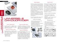
OVERVIEWOVERVIEW SUNMASTER <strong>XL</strong> ENCLOSUREHoisting eye (2x)Slots for mounting ofthe front plate (2x)Hoisting eye (2x)Powermodule 1Powermodule 2Powermodule 3User interfaces(indication LED’s)Support bar forpower modulesAC and DCconnections of thepower modulesMounting profilereserved for DCDIN railMounting profilereserved for ACDIN railIdentification labelCable glandsNote: DIN rails and components for AC / DC distribution are not included with the standard delivery.Figure 1: Inside view of the <strong>Sunmaster</strong> <strong>XL</strong>, including the power modules2 Copyright © 2011 Mastervolt / January 2011 / <strong>Sunmaster</strong> <strong>XL</strong> / EN
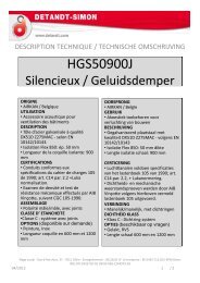
Designed by Mastervolt and manufactured in ChinaPV insulationTemperatureGrid qualitySolar highGrid faultDiagnostic3-Phase blockOVERVIEWOVERVIEW POWER MODULE<strong>XL</strong>5000 onlyWire seal facilityPart no : 44020400Type : <strong>Sunmaster</strong> <strong>XL</strong>Input :Input :Output :serial no: V8220001AIP23Identification labelCooling fans<strong>XL</strong> Power Module100%75%50%25%OnUser interfaceIndication LEDsFront viewAC output: L, N, PEPositive DC input(MultiContact)RS485 connectors (2x)(QS-DataBus)Negative DC input(MultiContact)Bottom viewDIP switchesMasterBus connectors (2x)Figure 2: Front view and bottom view of the power moduleEN / <strong>Sunmaster</strong> <strong>XL</strong> / January 2011 / Copyright © 2011 Mastervolt 3
CONTENTSCONTENTS: v 1.8 January 20111 GENERAL INFORMATION.............................................................................................................................................. 61.1 Product description............................................................................................................................................. 61.2 Use of this manual.............................................................................................................................................. 61.3 Validity of this manual ........................................................................................................................................ 61.4 Guarantee specifications.................................................................................................................................... 61.5 Liability ............................................................................................................................................................... 61.6 Changes to the <strong>Sunmaster</strong> <strong>XL</strong> ........................................................................................................................... 61.7 Identification labels............................................................................................................................................. 62 SAFETY GUIDELINES AND WARNINGS....................................................................................................................... 72.1 Warnings and symbols ....................................................................................................................................... 72.2 Use for intended purpose ................................................................................................................................... 72.3 Organisational measures ................................................................................................................................... 72.4 Installation, maintenance and repair................................................................................................................... 72.5 Warning of special dangers................................................................................................................................ 73 HOW IT WORKS.............................................................................................................................................................. 84 BEFORE YOU START..................................................................................................................................................... 94.1 Transport, lifting and storage.............................................................................................................................. 94.2 Unpacking .......................................................................................................................................................... 94.3 Apparatus version .............................................................................................................................................. 94.4 Installation environment ................................................................................................................................... 104.5 Opening and closing the enclosure .................................................................................................................. 104.6 Placing the power modules .............................................................................................................................. 114.7 Grounding and surge protection ....................................................................................................................... 114.7.1 General............................................................................................................................................ 114.7.2 Optional DC grounding .................................................................................................................... 114.7.3 Lightning protection ......................................................................................................................... 114.8 Three phase AC configuration.......................................................................................................................... 124.8.1 Phase balance protection circuit...................................................................................................... 124.8.2 Monitoring wiring RS485 ................................................................................................................. 124.8.3 AC Wiring is intended for use .......................................................................................................... 124.9 DC Connections ............................................................................................................................................... 134.9.1 General............................................................................................................................................ 134.9.2 Specifications of the PV-installation................................................................................................. 134.9.3 DC Switch........................................................................................................................................ 144.10 Typical PV-installations .................................................................................................................................... 144.10.1 Connection of six strings ................................................................................................................. 144.10.2 Connection of more than six strings ................................................................................................ 154.11 Remote monitoring ........................................................................................................................................... 155 INSTALLATION AND COMMISSIONING...................................................................................................................... 165.1 Things you need for installation........................................................................................................................ 165.2 Installation step by step.................................................................................................................................... 175.3 Instructions for use in Italy................................................................................................................................ 175.4 Commissioning after installation....................................................................................................................... 175.4.1 Switching on .................................................................................................................................... 174 Copyright © 2011 Mastervolt / January 2011 / <strong>Sunmaster</strong> <strong>XL</strong> / EN
CONTENTS6 OPERATION .................................................................................................................................................................. 186.1 General ............................................................................................................................................................ 186.2 User Interface................................................................................................................................................... 186.2.1 Normal operation............................................................................................................................. 186.2.2 Failures............................................................................................................................................ 196.3 Forced Cooling ................................................................................................................................................. 206.4 Maintenance..................................................................................................................................................... 206.4.1 Air filter ............................................................................................................................................ 206.4.2 Electrical connections...................................................................................................................... 207 TROUBLE SHOOTING.................................................................................................................................................. 217.1 Fault finding table ............................................................................................................................................. 217.2 Decommissioning ............................................................................................................................................. 218 SPECIFICATIONS ......................................................................................................................................................... 228.1 Technical specifications ................................................................................................................................... 228.2 Outline drawings............................................................................................................................................... 249 ORDERING INFORMATION.......................................................................................................................................... 2510 SELF TEST ITALY......................................................................................................................................................... 2611 CERTIFICATES ............................................................................................................................................................. 3011.1 EC declaration of conformity ............................................................................................................................ 3011.2 VDE0126-1-1 Certificate of compliance ........................................................................................................... 31EN / <strong>Sunmaster</strong> <strong>XL</strong> / January 2011 / Copyright © 2011 Mastervolt 5
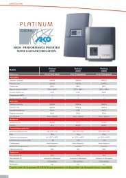
GENERAL INFORMATION1 GENERAL INFORMATION1.1 PRODUCT DESCRIPTIONCongratulations for choosing the Mastervolt <strong>Sunmaster</strong> <strong>XL</strong><strong>10K</strong>/ <strong>XL</strong> <strong>15K</strong>, further referred to as “<strong>Sunmaster</strong> <strong>XL</strong>”. The<strong>Sunmaster</strong> <strong>XL</strong> is a grid connected solar inverter, used forthe feed back into a three phase utility grid of powergenerated by photovoltaic modules.Depending on the application and in order to meet thelocal applicable regulations, the <strong>Sunmaster</strong> <strong>XL</strong> can beordered in several models. See section 4.3 for an overviewof the available models.The <strong>Sunmaster</strong> <strong>XL</strong> is not suitable for stand-alone use (i.e.use without public grid).1.2 USE OF THIS MANUALCopyright © 2011 Mastervolt. All rights reserved.Reproduction, transfer, distribution or storage of part or allof the contents in this document in any form without theprior written permission of Mastervolt is prohibited.This manual serves as a guideline for the safe andeffective installation of the <strong>Sunmaster</strong> <strong>XL</strong>:• For the electrician this manual gives directions for theinstallation, operation and commissioning.• For the end-user this manual gives directions for theoperation, maintenance and possible correction ofminor malfunctions of the <strong>Sunmaster</strong> <strong>XL</strong>.• Every person who works with the apparatus should befamiliar with the contents of this manual, and mustcarefully follow the instructions contained herein.• Store the manual in a user accessible place.This English manual has 32 pages.1.3 VALIDITY OF THIS MANUALAll the specifications, provisions and instructions containedin this manual apply solely to the Mastervolt-deliveredstandard versions of the <strong>Sunmaster</strong> <strong>XL</strong> (refer to section4.3).1.4 GUARANTEE SPECIFICATIONSMastervolt assures the product guarantee of the<strong>Sunmaster</strong> <strong>XL</strong> during five years after your purchase, onthe condition that all instructions and warnings given in thismanual are taken into account during installation andoperation.Among other things, this means that installation is carriedout by a qualified electrician, that installation andmaintenance are executed according to the statedinstructions and correct working sequence and that nochanges or repairs may have been performed on the<strong>Sunmaster</strong> <strong>XL</strong> other than by Mastervolt.The warranty is limited to the costs of repair and/orreplacement of the product by Mastervolt only. Costs forinstallation labour or shipping of the defective parts are notcovered by this warranty.For making an appeal on warranty you can directly contactyour supplier, stating your complaint, application, date ofpurchase and part number / serial number1.5 LIABILITYMastervolt accepts no liability for:• consequential damage due to use of the <strong>Sunmaster</strong><strong>XL</strong>;• possible errors in the manuals and the results thereof.• loss of energy revenues due to possible defects1.6 CHANGES TO THE SUNMASTER <strong>XL</strong>Changes on the <strong>Sunmaster</strong> <strong>XL</strong> may be carried out onlyafter the written permission of Mastervolt1.7 IDENTIFICATION LABELSFigure 3See figures 1, 2 and 3 for location of the identificationlabels. Important technical information required for service,maintenance & secondary delivery of parts can be derivedfrom the identification labels (figure 2).A small serial number sticker is provided witheach power module. Stick these on thereserved locations of the <strong>Sunmaster</strong> <strong>XL</strong> label.See figure 3, #1, #2 and #3.CAUTION!Never remove the identification label(s).6 Copyright © 2011 Mastervolt / January 2011 / <strong>Sunmaster</strong> <strong>XL</strong> / EN
SAFETY GUIDELINES AND WARNINGS2 SAFETY GUIDELINES AND WARNINGS2.1 WARNINGS AND SYMBOLSSafety instructions and warnings are marked in thismanual by the following pictograms:A procedure, circumstance, etc whichdeserves extra attention.CAUTION!Special information, commands andprohibitions in order to prevent damage.WARNINGA WARNING refers to possible injury to theuser or installer or significant material damageto the <strong>Sunmaster</strong> <strong>XL</strong> if the installer / user doesnot (carefully) follow the stated procedures.2.2 USE FOR INTENDED PURPOSEThe <strong>Sunmaster</strong> <strong>XL</strong> is constructed as per the applicablesafety-technical guidelines. Use the <strong>Sunmaster</strong> <strong>XL</strong> only ininstallations that meet the following qualifications:• in permanent installations;• connected to a separate, grounded three phase ACgroup, to which no other electrical equipment isconnected;• the electrical installation must meet the applicableregulations and standards, must be carried outcorrectly and must be in a good condition.• according to the technical specifications as stated inchapter 8.1.WARNINGNever use the <strong>Sunmaster</strong> <strong>XL</strong> in situationswhere there is danger of gas or dust explosionor potentially flammable products!Use of the <strong>Sunmaster</strong> <strong>XL</strong> other than as mentioned under §2.2 and 4.4 is not considered to be consistent with theintended purpose. Mastervolt is not liable for any damageresulting from the above.2.3 ORGANISATIONAL MEASURESThe installer / user must always:• have access to this manual;• be familiar with the contents of this manual. Thisapplies particularly to Chapter 2, Safety Guidelines &Warning.2.4 INSTALLATION, MAINTENANCE ANDREPAIRAs lethal voltages exist, allow installation, maintenanceand repair of the <strong>Sunmaster</strong> <strong>XL</strong> and changes in yourelectrical system to be carried out by qualified electriciansonly.Connections and safety features must be executedaccording to the locally applicable regulations.In case of decommissioning and/or demounting follow theinstructions as stated in section 7.2If such are required, use only original spare parts.2.5 WARNING OF SPECIAL DANGERS• Not only AC-grid voltage, but DC voltages up to 600Vmay exist in the <strong>Sunmaster</strong> <strong>XL</strong> as well.• The voltages present at the grid and solar side of the<strong>Sunmaster</strong> <strong>XL</strong> are not safe to touch and cannot beswitched off at the solar side. Depending on localapplicable regulations the use of an internal or externalDC switch may be obligatory.• Do not work on the <strong>Sunmaster</strong> <strong>XL</strong> and/or the electricalinstallation if it is still connected to the solar panelsand/or AC-grid.• Only allow changes in your electrical system to becarried out by qualified electricians.• A <strong>Sunmaster</strong> <strong>XL</strong> with a known defective condition mustbe switched off immediately. To do so, first switch offthe AC, then disconnect the solar wiring (refer tosection 7.2).EN / <strong>Sunmaster</strong> <strong>XL</strong> / January 2011 / Copyright © 2011 Mastervolt 7
HOW IT WORKS3 HOW IT WORKSThe <strong>Sunmaster</strong> <strong>XL</strong> converts the energy from a PV arrayand feeds this energy back to the electric grid. Themechanical layout of the electrical components in the<strong>Sunmaster</strong> <strong>XL</strong> is of a modular concept and housed in anIP55 enclosure.See figure 4. The <strong>Sunmaster</strong> <strong>XL</strong> consists of three identicalpower modules, indicated as “SOLAR 1”, “SOLAR 2” and“SOLAR 3”. These separate power modules have theirown individual system control, monitoring and protection.Each power module can convert up to 3.5 or 5 kW,depending on the model. This means that the <strong>Sunmaster</strong><strong>XL</strong> can convert up to 10 or 15kW. The DC voltage range ofthe power modules is 100-550V DC (<strong>XL</strong>3301) or 100-600VDC (<strong>XL</strong>5000).The AC-outputs are connected in a 230 V AC three-phasestar configuration. Islanding protection is providedaccording to national standards. If one of the phases of theAC-grid fails in operation, all power modules will switch offimmediately. A communication cable must be used forcommunication between the power modules.Extended diagnostics and remote monitoring may beordered as an option.<strong>Sunmaster</strong> <strong>XL</strong>Solarinput 3DC“SOLAR 3”ACSolarinput 2DC“SOLAR 2”ACSolarinput 1DC“SOLAR 1”ACFigure 4: principle operation of the <strong>Sunmaster</strong> <strong>XL</strong>8 Copyright © 2011 Mastervolt / January 2011 / <strong>Sunmaster</strong> <strong>XL</strong> / EN
BEFORE YOU START4 BEFORE YOU START4.1 TRANSPORT, LIFTING AND STORAGEEnsure adequate and secure mounting duringtransportation of the <strong>Sunmaster</strong> <strong>XL</strong>. Always use suitablehandling equipment for transportation. On top of theenclosure are four hoist eyes which can be used for liftingand transportation (see figure 1). To avoid damage, useslings for lifting.When lifting the <strong>Sunmaster</strong> <strong>XL</strong> avoid any riskof personal injuries, do not stand under the<strong>Sunmaster</strong> <strong>XL</strong>.4.2 UNPACKINGThe delivery of the <strong>Sunmaster</strong> <strong>XL</strong> consists of:• 1 <strong>Sunmaster</strong> <strong>XL</strong> enclosure• 3 <strong>XL</strong> power modules with AC wiring attached• 6 multicontact DC cables• 1 cable gland + 2 caps PG21• 14 cable glands + 12 caps PG9• 2 MasterBus communication cables• 2 MasterBus terminating devices• This user’s and installation manual.After unpacking, check the contents for possible damage.Do not use the product if is damaged. If in doubt, contactyour supplier.As one electrical installation differs from the other, the<strong>Sunmaster</strong> <strong>XL</strong> is delivered without fuses, circuit breakers,terminal blocks, mains switches and DC-switches4.3 APPARATUS VERSIONThe <strong>Sunmaster</strong> <strong>XL</strong> is equipped with an anti-islandingdevice that ensures the switch off in case of grid failure.European countries maintain different regulations withregard to anti-islanding devices and grid connection ofdistributed generation in general. The common islandingdevice switches off the inverter if the grid voltage orfrequency is out of range. In some countries like Germanythe ENS device (VDE-V-0126-1-1 compliant) which alsomeasures the grid impedance, is compulsory.Mastervolt provides both versions of the <strong>Sunmaster</strong> <strong>XL</strong>.These versions are available as several alternatives,suited to national regulations.Check from the part number on the type number platewhether the <strong>Sunmaster</strong> <strong>XL</strong> is appropriate to be used forthe intended application (refer to table 1).CAUTION!NEVER connect the <strong>Sunmaster</strong> <strong>XL</strong> to a utilitygrid other than specified (refer to table 1).Part number DescriptionPart numberAllowed to be used in:<strong>Sunmaster</strong> <strong>XL</strong>Power module131110000 <strong>Sunmaster</strong> <strong>XL</strong> 10 kW 131103300*/ 131103301* - see section 4.8 -131110010 <strong>Sunmaster</strong> <strong>XL</strong> 10 kW – NLD 131103311 Netherlands131110020 <strong>Sunmaster</strong> <strong>XL</strong> 10 kW – BEL 131103321 max. 3333W AC Belgium131110030 <strong>Sunmaster</strong> <strong>XL</strong> 10 kW – ENS 131103330/ 131103331 Germany, France, Austria131110040 <strong>Sunmaster</strong> <strong>XL</strong> 10 kW – KOR 131103340/ 131103341 South Korea131110050 <strong>Sunmaster</strong> <strong>XL</strong> 10 kW – ESP 131103350/ 131103351 Spain131110060 <strong>Sunmaster</strong> <strong>XL</strong> 10 kW – GBR 131103360/ 131103361 Great Britain131110070 <strong>Sunmaster</strong> <strong>XL</strong> 10 kW – ITA 131103370/ 131103371 Italy131110080 <strong>Sunmaster</strong> <strong>XL</strong> 10 kW –GRC 131103380/ 131103381 Greece131110xxx <strong>Sunmaster</strong> <strong>XL</strong> 10 kW 131103400/ 131103401. Australia131115000 <strong>Sunmaster</strong> <strong>XL</strong> 15 kW 131105000* - see section 4.8 -131110010 <strong>Sunmaster</strong> <strong>XL</strong> 15 kW – NLD 131105010 Netherlands131115030 <strong>Sunmaster</strong> <strong>XL</strong> 15 kW – ENS 131105030 Germany, France, Austria131115040 <strong>Sunmaster</strong> <strong>XL</strong> 15 kW – KOR 131105040 South Korea131115010 <strong>Sunmaster</strong> <strong>XL</strong> 15 kW – NLD 131105010 Netherlands131115050 <strong>Sunmaster</strong> <strong>XL</strong> 15 kW – ESP 131105050 Spain131115060 <strong>Sunmaster</strong> <strong>XL</strong> 15 kW – GBR 131105060 Great Britain131115070 <strong>Sunmaster</strong> <strong>XL</strong> 15 kW – ITA 131105070 Italy131115080 <strong>Sunmaster</strong> <strong>XL</strong> 15 kW –GRC 131105080 Greece131115xxx <strong>Sunmaster</strong> <strong>XL</strong> 10 kW 131105100 Australia* These models must be configured at first installation. See Appendix for configuration instructions.Table 1EN / <strong>Sunmaster</strong> <strong>XL</strong> / January 2011 / Copyright © 2011 Mastervolt 9
BEFORE YOU START4.4 INSTALLATION ENVIRONMENTObey the following stipulations during installation:• The <strong>Sunmaster</strong> <strong>XL</strong> is designed for both indoor andoutdoor use, according to safety class IP55.• The <strong>Sunmaster</strong> <strong>XL</strong> must be mounted in vicinity of thesolar panels.• Do not install the <strong>Sunmaster</strong> <strong>XL</strong> in dusty environments• Ambient temperature: -20 ... 60°C; (power deratingabove 45°C).• Keep at least 50 cm space at the front side and backside of the <strong>Sunmaster</strong> <strong>XL</strong> and 30 cm between the <strong>XL</strong>enclosures, see figure 5.• If the <strong>Sunmaster</strong> <strong>XL</strong> is installed in the immediatevicinity of living areas, take into account that the<strong>Sunmaster</strong> <strong>XL</strong> can produce a certain noise level whenoperating (refer to section 6.3).• The <strong>Sunmaster</strong> <strong>XL</strong> must be mounted vertically on asolid floor.• The wiring is connected inside the enclosure. Alwaysfeed the wiring through the cable glands of theenclosure, and then connect the wiring to theterminals. Close unused holes with the caps supplied.Figure 6Proceed as follows to close the enclosure:• Hang the front plate in the two slots at the top of thefront side (see figure 1).• Fix the earth cable to the front plate again.• Fix the two hexagonal bolts at the lower side of thefront plate (see figure 6).50 cm30cm30cmTop30cm50 cmFrontFigure 54.5 OPENING AND CLOSING THEENCLOSURECAUTION!Make sure that you do not disconnect nordamage the green/yellow ground connectioncable which is attached to the inner side of thefront plate.Figure 7For opening of the enclosure execute the steps below:• Loosen the two hexagonal bolts at the lower side of thefront plate (see figure 6).• Lift the front plate from the enclosure (see figure 7).• Disconnect the earth cable that is fixed to the frontplate.10 Copyright © 2011 Mastervolt / January 2011 / <strong>Sunmaster</strong> <strong>XL</strong> / EN
BEFORE YOU START4.6 PLACING THE POWER MODULES• Remove the support bar (figure 8) by unscrewing thetwo bolts.• Place the power modules into the enclosure, facing thewiring and the connectors downwards. Hold the topfront edge between the tongues of the top support barand turn the power module into position (see figure 9).Avoid damaging the MultiContact connectors of thepower modules!• Fix the support bar (figure 8) by fastening the two boltsagain. Make sure that all power modules are securelyfixed in place by the support bar.BoltBolt4.7 GROUNDING AND SURGE PROTECTION4.7.1 GeneralThe enclosure of the <strong>Sunmaster</strong> <strong>XL</strong> must be connected toprotective earth (PE) by means of an equipment-groundingconductor. For this purpose a grounding terminal issituated at the lower right corner inside of the enclosure(see figure 10). The power modules PE cable must begrounded according to figure 12, section 4.8.3.Grounding of the solar array is not obligatory thanks to thegalvanic isolation between the DC-input and the AC outputof the <strong>Sunmaster</strong> <strong>XL</strong>. However, if you want to make aconnection between the solar array structure and theground, you need to lead the grounding cable togetherwith the DC-cables to the <strong>Sunmaster</strong> <strong>XL</strong> and then to theAC distribution. Connect the grounding cable going fromthe PV-modules to the AC-distribution and the groundingterminal of the <strong>Sunmaster</strong> <strong>XL</strong>.Support barFigure 8GroundingterminalFigure 104.7.2 Optional DC groundingGrounding of the positive or negative DC wiring ispossible. The insulation protection function should bedisabled. Refer to the Mastervolt M 2397 “Array groundingtechnical bulletin” for background information andinstructions.4.7.3 Lightning protectionDue to large distances between the components of a solarinstallation, precautions must be taken to avoid damagefrom induced surges caused by lightning. Although thepower modules are designed to withstand overvoltages,Mastervolt recommends to consult a specialist on lightningprotection systems for advice.Figure 9EN / <strong>Sunmaster</strong> <strong>XL</strong> / January 2011 / Copyright © 2011 Mastervolt 11
BEFORE YOU START4.8 THREE PHASE AC CONFIGURATION4.8.1 Phase balance protection circuitDepending on local regulations, all power modules mustswitch off immediately as soon as one of the phases of theAC-grid fails in operation. To achieve this, communicationbetween the power modules is necessary. This is done bymeans of communication cables.Take the following steps to configure the power modulesfor three phase operation:• Connect the MasterBus communication cables and theMasterBus terminating devices as indicated in figure10. The MasterBus communication ports can be foundat the bottom side of the power modules (figure 2).Make sure that you neither connect theMasterBus communication cables nor theMasterBus terminating devices to the RS485communication ports (see figure 10)!4.8.2 Monitoring wiring RS485For correct monitoring the three power modules have to beconnected serially, using RS485 cables. These are to beinserted into the Communication ports, see figure 11.4.8.3 AC Wiring is intended for useThe <strong>Sunmaster</strong> <strong>XL</strong> is intended for use in a in a permanentinstallation, connected to a separate three phase ACdistribution group, to which no other electrical equipment isconnected.All electrical connections must comply with local codesand regulations.The AC-outputs of the three power modules must bearranged in a 230 V AC three-phase star configuration.The cabling between the junction box or electric cable ductand the <strong>Sunmaster</strong> <strong>XL</strong> must be double insulated. Use anappropriate cross section, so that the cable loss is wellbelow 1%.Recommended cross sections for 10m cable length:• The default setting of DIP switch 1 (3-phase block) isON. Do NOT change the setting of the DIP switches(see figure 2).Model<strong>Sunmaster</strong> <strong>XL</strong> 10kW<strong>Sunmaster</strong> <strong>XL</strong> 15kWMinimum cross section:2,5mm²4,0mm²See figure 12 for a typical three phase ACconfiguration.MasterBus communication cableRS485RS485RS485MasterBus terminating deviceFigure 11: Communication ports of the <strong>Sunmaster</strong> <strong>XL</strong>12 Copyright © 2011 Mastervolt / January 2011 / <strong>Sunmaster</strong> <strong>XL</strong> / EN
BEFORE YOU START<strong>Sunmaster</strong> <strong>XL</strong>+–DC“SOLAR 3”ACLNPE+–+–DC“SOLAR 2”ACDC“SOLAR 1”ACLNPELNPEFigure 13A:. MasterBus communication cable(see section 4.8.2)B PE terminal blockC: N terminal blockD: Three phase circuit breakerRecommended rating:<strong>Sunmaster</strong> <strong>XL</strong> 10kW: 25A<strong>Sunmaster</strong> <strong>XL</strong> 15kW: 32AFigure 12: AC wiring4.9 DC CONNECTIONS4.9.1 GeneralThe <strong>Sunmaster</strong> <strong>XL</strong> consists of three separate inverters,indicated as “SOLAR 1”, “SOLAR 2” and “SOLAR 3”.Refer to figure 13.The solar or DC side of the system consists of severalphotovoltaic (solar) modules, further referred to as “PVmodules”. The PV-modules are connected in series toform a so called “string”. These strings consist of a plus (+)and a minus (–) connection which can be connecteddirectly to the <strong>Sunmaster</strong> <strong>XL</strong>.4.9.2 Specifications of the PV-installationThe PV-installation should meet the followingspecifications:• Double isolated PV-wiring, fitted with MultiContactconnectors must be used.• The maximum power connected to each power modulemay not exceed 4600Wp (<strong>XL</strong>3301) or 6700Wp(<strong>XL</strong>5000).• The total input power must be distributed equally overthe three power modules as much as possible.• All connection devices (wiring, terminal blocks, fuseholders, fuses, switches, etcetera) must be suitable forthe applicable voltage (up to 600V DC) and currentratings (up to 30A DC) of the solar installation.• The maximum open circuit string voltage for eachpower module at lowest possible temperature of thePV modules may not exceed 550V (<strong>XL</strong>3301) or 600V(<strong>XL</strong>5000).To avoid miswiring, check the open circuit voltage andpolarity of each string with a suitable DC voltage meterbefore connection. The nominal value of the open circuitstring voltage (Voc) is calculated for each string as follows:[Nominal String Voc] =[PV module Voc] (*) x [number of modules].(*) For PV module Voc value, refer to the specifications ofthe modulesEN / <strong>Sunmaster</strong> <strong>XL</strong> / January 2011 / Copyright © 2011 Mastervolt 13
BEFORE YOU STARTDepending on temperature and irradiation on the PVmodule array, the measured value should be equal to 70-100% of the calculated value. To match the specificationsof the <strong>Sunmaster</strong> <strong>XL</strong> power modules, the measuredvoltage should be as follows:Model<strong>Sunmaster</strong> <strong>XL</strong> 10kW<strong>Sunmaster</strong> <strong>XL</strong> 15kWMeasured Voc:290 - 550VDC225 - 600VDCCAUTION!Do not install the <strong>Sunmaster</strong> <strong>XL</strong> if the solarsystemdoes not comply with the abovementioned stipulations.See section 4.10 for examples of typical PVinstallations.4.10 TYPICAL PV-INSTALLATIONSNote that the maximum power connected toeach power module may not exceed 4600Wp(<strong>XL</strong>3301) or 6700Wp (<strong>XL</strong>5000) and that thetotal input power must be distributed equallyover the three power modules as much aspossible.4.10.1 Connection of six stringsSee figure 14.If two strings are connected to the same power module,DIN-rail mounted terminals blocks must be applied tocombine the strings. The strings connected to the samepower module should exist of an equal number of identicalPV-modules.4.9.3 DC SwitchDepending on local applicable regulations the use of a DCswitch between the PV modules and the power modulesmay be mandatory. For example international standardIEC60364-7-712 prescribes a DC switch in solar electricinstallations in buildings. Refer to chapter 9 for orderinginformationConnections to be made by means of DC DIN-rail mounted terminal blocks<strong>Sunmaster</strong> <strong>XL</strong>DC“SOLAR 3”ACDC“SOLAR 2”ACDC“SOLAR 1”ACFigure 14: Connection of six strings14 Copyright © 2011 Mastervolt / January 2011 / <strong>Sunmaster</strong> <strong>XL</strong> / EN
BEFORE YOU START4.10.2 Connection of more than six stringsSee figure 15.If more than two strings are connected to the same Solarinput,string fuses must be integrated in both the positiveand negative legs of the string cabling. Fuse ratingsshould be chosen 50 % higher than the MPP current of thePV modules used. DIN-rail mounted terminals blocksand/or fuse holders can be applied to combine the strings.The strings connected to the same Solar-input should existof an equal number of identical PV-modules.4.11 REMOTE MONITORINGEach power module is provided with two RS485connectors for connection of the QS Databus.See figure 2.Mastervolt provides several monitoring solutions like PCsoftware, dataloggers, remote monitoring and so on.Consult our web-site at www.mastervolt.com for acomprehensive overview of all possibilities.Make sure that you do not mistake the RS485Databus for the MasterBus communicationports (see figure 2)!Connections to be made by means of DIN-rail mounted terminal blocks<strong>Sunmaster</strong> <strong>XL</strong>+–DC“SOLAR 3”AC+–DC“SOLAR 2”AC+–DC“SOLAR 1”ACString fuses in positiveand negative legsFigure 15: Connection of more than six stringsEN / <strong>Sunmaster</strong> <strong>XL</strong> / January 2011 / Copyright © 2011 Mastervolt 15
INSTALLATION AND COMMISSIONING5 INSTALLATION AND COMMISSIONINGCAUTION!Read chapters 2 and 4 prior to installation.WARNINGBe sure that all wiring is disconnected fromany power source during the entireinstallation.CAUTION!• Short circuiting, reverse polarity orinterchanging of PV strings may lead todamage to the <strong>Sunmaster</strong> <strong>XL</strong>, the cablingand/or the terminal connections.• Follow all steps of the installationinstructions in order of succession asdescribed.• If applied, both the DC switches and theAC circuit breaker(s) should stay in theOFF-postion (or “O”-position) during theentire installation.CAUTION!Danger of damaging the power module incase of mis wiring. To avoid mis wiring, checkthe open circuit voltage and polarity of eachstring with a suitable DC voltage meter beforeconnection; see section 4.9.2.WARNINGHigh voltages (up to 600 VDC) may exist onthe PV-strings! Connection of the DC-cablingmay only be carried out if the DC-cables arevoltage free. Therefore the PV-modules mustbe disconnected from the DC-cabling (forinstance by disconnecting the MultiContactconnectors at the PV-modules).5.1 THINGS YOU NEED FOR INSTALLATIONMake sure you have all the parts you need to install the<strong>Sunmaster</strong> <strong>XL</strong>:• <strong>Sunmaster</strong> <strong>XL</strong> enclosure (included)• Three power modules (included)• Cable glands and grommets (included)• 2 MasterBus communication cables (included)• 2 MasterBus terminating devices (included)• Bolts and dowels to fix the <strong>Sunmaster</strong> <strong>XL</strong> enclosure tothe ground. Use mounting materials that are suitablefor the application• 2 DIN-rails (50cm) for mounting of breakers, fuseholders, switches, terminal blocks• DIN-rail mounted terminal blocks to connect the DCwiring• DIN-rail mounted DC-switches to switch off the solarstrings (if applicable; see section 4.9.3)• DIN-rail mounted fuse holders and fuses for theconnection of the solar strings (if applicable; seesection 4.10.2)• DIN-rail mounted terminal blocks, to configure the ACoutputs of the power modules for three phase gridconnection• Three phase AC circuit breaker, see section 4.8• WiringRequired tools:• Tools to fix <strong>Sunmaster</strong> <strong>XL</strong> enclosure to the floor• Hexagon socket wrench (5mm) to open and close theenclosure of the <strong>Sunmaster</strong> <strong>XL</strong>• Socket wrench 10 mm to remove and fix the supportbar (see section 4.6)• Tools to install the wiring.16 Copyright © 2011 Mastervolt / January 2011 / <strong>Sunmaster</strong> <strong>XL</strong> / EN
INSTALLATION AND COMMISSIONING5.2 INSTALLATION STEP BY STEP5.4 COMMISSIONING AFTER INSTALLATION1 Fix the enclosure of the <strong>Sunmaster</strong> <strong>XL</strong> to the floor.Determine the mounting spots on the basis of figure19. Use suitable screws and dowels.To check the correct operation of the<strong>Sunmaster</strong> <strong>XL</strong>, commissioning should becarried out during daytime only.2 Open the enclosure of the <strong>Sunmaster</strong> <strong>XL</strong> (see section4.5).3 Connect system grounding (section 4.7).4 Place the power modules in the enclosure (see section4.6).5 Configure the power modules for three phaseoperation (see section 4.8.1).6 Connect the AC-wiring (see section 4.8.3).7 Check whether the PV-installation matches with thespecifications of the power modules (see section 4.9).Then connect the DC Solar wiring (see section 4.10).5.4.1 Switching onFollow the steps described below to switch on the<strong>Sunmaster</strong> <strong>XL</strong>:1 Check whether the DC switches (if applied) and theAC circuit breaker(s) are still in the OFF position.2 Move the DC-switch (if applied) of the solar array tothe ON position.3 Check the part number on the power moduleidentification label (see section 1.7). If the partnumber ends with 01 or 00 (e.g. 131103301 or131115000) the <strong>Sunmaster</strong> <strong>XL</strong> must be configured inaccordance with the local regulations for gridconnection first. Refer to the APPENDIX.8 Option: connect the QS Databus to the RS485connectors of the power modules (see section 4.11).5.3 INSTRUCTIONS FOR USE IN ITALYIn Italy ENEL may require sealing parts of theAC wiring.All power modules are equipped with a wire seal facility.Figure 2 shows where this is located. A detailed view isshown in figure 16.As long as the <strong>Sunmaster</strong> <strong>XL</strong> is notconfigured in accordance with the localregulations for grid connection, the powermodules will stay in idle mode. This meansthat no power can be converted.4 Switch on the AC grid.5 Check the AC voltage at the grid side of the AC circuitbreaker using a suitable AC voltmeter. The voltagesshould be as follows:AC Voltage:L1 N 230V AC (184-276V)L2 N 230V AC (184-276V)L3 N 230V AC (184-276V)L1 L2 400V AC (320-475V)L2 L3 400V AC (320-475V)L3 L1 400V AC (320-475V)6 If the AC voltages are correct, move the AC circuitbreaker to the ON position.If connection has been made correctly and solar irradiationis sufficient, the <strong>Sunmaster</strong> <strong>XL</strong> will switch on automatically.This may take a few seconds.Figure 16: Detailed view of wire seal facility7 Close the enclosure of the <strong>Sunmaster</strong> <strong>XL</strong> (see section4.5).EN / <strong>Sunmaster</strong> <strong>XL</strong> / January 2011 / Copyright © 2011 Mastervolt 17
OPERATION6 OPERATION6.1 GENERALAfter installation and commissioning the <strong>Sunmaster</strong> <strong>XL</strong> willswitch on automatically if solar irradiation is sufficient. The<strong>Sunmaster</strong> <strong>XL</strong> operates automatically: there is no need foroperating it. If the irradiation of the PV-modules isinsufficient, for instance at night, the <strong>Sunmaster</strong> <strong>XL</strong>switches off automatically. When switched off, none of theLED indications on front of the power modules willilluminate.The <strong>Sunmaster</strong> <strong>XL</strong> has no ON/OFF switch; In the event ofdecommissioning, refer to section 7.2.CAUTION!Never disconnect the MultiContact plugsduring operation of the <strong>Sunmaster</strong> <strong>XL</strong>.Not complying with this instruction may causea spark or an electric arc. Should an arcdevelop, both plug and socket of the<strong>Sunmaster</strong> <strong>XL</strong> must be replaced.6.2 USER INTERFACEThe operation of the <strong>Sunmaster</strong> <strong>XL</strong> is displayed by meansof LED indicators at the front side of each power module(figure 17).6.2.1 Normal operationIf the module is operating normally (the yellow and the redindicator are not illuminated or flashing), the green LEDindicatorsshow the amount of power that is fed into thegrid: the more LED’s illuminate, the more power isconverted.As long as the red and yellow LED’s are notilluminated, no failure is detected: the<strong>Sunmaster</strong> <strong>XL</strong> is operating normally!If the irradiation of the PV-modules isinsufficient, for instance at night, the LEDindicators will switch off automatically. This isa normal situation!Power conversion (Wac)<strong>Sunmaster</strong> <strong>XL</strong> 10kW <strong>Sunmaster</strong> <strong>XL</strong> 15kW2870–3465 4350–52502050–2870 3100–43501220–2050 1850–3100400–1220 600–18500–400 0–600Green, OnGreen, OnGreen, OnGreen, OnGreen, OnThe inverter is starting up.This can take up to 300 sec.BlinkingFigure 17 LED illumination during normal operation of the inverter modulesRed, OffYellow, Off18 Copyright © 2011 Mastervolt / January 2011 / <strong>Sunmaster</strong> <strong>XL</strong> / EN
OPERATION6.2.2 FailuresIf one or more of the phases of the AC-grid fails inoperation the yellow “3 phase block” LED will illuminate onall power modules. See also section 4.8.1In case of a hardware failure on one of the powermodules, the red “diagnostic” LED illuminates or flashes incombination with one or more green LEDs.Refer to chapter 7 for an explanation of the power- andfailure indications. Consult an installer, if you cannot solvethe problem by means of this table.PV Insulation: Leak current between PVmodulesand grounding. Contact your supplier.Temperature: Temperature of the inverter istoo high. Is the airflow of the inverter blocked?Grid quality: Fault created by the ENS-unit.The grid quality is outside normal limits. Checkthe grid connection.Solar high: The DC voltage of the Solar input istoo high. Contact your supplier.Grid fault: The grid is cut off or outside itslimits. Check the grid connection.OnBlinkingOnInternal error in the <strong>Sunmaster</strong> <strong>XL</strong>. Consult aninstaller for replacement of the inverter module.One or more of the phases of the AC-grid failsin operation. Check the AC gridFigure 18: LED iIlumination in case of a failureEN / <strong>Sunmaster</strong> <strong>XL</strong> / January 2011 / Copyright © 2011 Mastervolt 19
OPERATION6.3 FORCED COOLINGFor an optimum internal temperature control each invertermodule is provided with three cooling fans. At low powerthe cooling fans start running slowly. If the powerincreases, the cooling fans will run at a higher speed. Thisis a normal effect which has a positive influence on theefficiency and lifetime of the <strong>Sunmaster</strong> <strong>XL</strong>.6.4 MAINTENANCEIf necessary, use a soft clean cloth to clean enclosure ofthe <strong>Sunmaster</strong> <strong>XL</strong>. Never use any liquids, acids and/orscourers.1 Front plate2 Air filter3 Filter holder6.4.1 Air filterThe <strong>Sunmaster</strong> <strong>XL</strong> is standard supplied with an air filterwhich is placed at backside of the front plate (figure 18).Filter maintenance depends on environmentalcontamination. Check the air filter at least every 6 months.See section 4.5 to open the housing of the <strong>Sunmaster</strong> <strong>XL</strong>.Clean or replace if necessary. See section 9 for orderinginformation.Figure 19: Air filter6.4.2 Electrical connectionsExamine your electrical installation on a regular base, atleast once a year. Defects such as loose connections,burnt wiring etc. must be corrected immediately.20 Copyright © 2011 Mastervolt / January 2011 / <strong>Sunmaster</strong> <strong>XL</strong> / EN
TROUBLE SHOOTING7 TROUBLE SHOOTING7.1 FAULT FINDING TABLEConsult an installer, if you cannot solve the problem by means of the table below.Problem Possible cause What to do?All LED indicators are off. Insufficient irradiation.Nothing. Irradiation of the PV modules is insufficient (forinstance during night time).DC-switch (if applied) in OFF position. Move DC-switch to the ON position.DC fuse (if applied) defect.Check string fuses.LED “3 phase block” at oneor more power modules isilluminated yellow.LED “Diagnostic” constantlyilluminated red and LED ‘on”blinking slowly green.Red LED “Diagnostic” at oneor more power modules isilluminated red.Red LED “Diagnostic” at oneor more power modules isblinking redNo power from the PV modules.<strong>Sunmaster</strong> <strong>XL</strong> is not configured inaccordance with the local regulationsfor grid connection.One or more of the phases of the ACgridfails in operation.One of the MasterBus communicationcables is looseMasterBus communication cablesconnected to the RS485 port(s)No terminating device placed at theends of the MasterBus networkStart-upCheck DC voltage. It should be 220-600V (<strong>XL</strong><strong>10K</strong>) or180-600V (<strong>XL</strong><strong>15K</strong>).Consult an installer if the display does not show anyinformation during daytime.See Appendix to configure the power modules.Check the AC grid voltages.Check MasterBus communication cables.MasterBus communication cables must be connected tothe MasterBus ports. See section 4.8.1See section 4.8.1Installation fault or grid fault See section 6.2.2Internal error in the <strong>Sunmaster</strong> <strong>XL</strong>power module.Nothing. After the <strong>Sunmaster</strong> <strong>XL</strong> was (re)connected tothe AC grid, it checks the quality of the AC grid before itstarts operating normally. This may take up to 5 minutes.Write down which LED’s are lighting or blinking.Consult an installer for replacement of the powermodule.7.2 DECOMMISSIONINGIf it is necessary to put the <strong>Sunmaster</strong> <strong>XL</strong> out of operation,follow the instructions in order of succession as describedbelow:CAUTION!Follow below mentioned instructions in orderof succession as described.1 Cut off the grid voltage by switching off AC distributionswitch in the meter cupboard.2 Move the AC circuit breaker to the OFF position.3 If such is applied, move the DC switch to the OFFposition.4 Check with a suitable voltage meter whether theinputs and the outputs of <strong>Sunmaster</strong> <strong>XL</strong> are voltagefree.5 Disconnect the MultiContact connectors from the<strong>Sunmaster</strong> <strong>XL</strong>.6 Disconnect the AC wiring.Now the <strong>Sunmaster</strong> <strong>XL</strong> can be demounted in a safe way.EN / <strong>Sunmaster</strong> <strong>XL</strong> / January 2011 / Copyright © 2011 Mastervolt 21
SPECIFICATIONS8 SPECIFICATIONS8.1 TECHNICAL SPECIFICATIONSGENERAL SPECIFICATIONSArticle number See chapter 4.3Typical string length5-9 modules (72 cells), 7-12 modules (54 cells) or 10-18 modules (36 cells)Operating temperatureStorage temperature -20°C to 60°CRelative humidityProtection degreeSafety classGalvanic isolation-20°C to 60°C ambient, full power up to 45°C, thereafter derating –3%/°C,(fully protected against over temperature)max. 95%; PCB has anti-moisture coatingIP55class Iclass IIDimensions See section 8.2.Weight95 kg [209 lbs] without power modules, 135 kg [298 lbs] including power modulesSOLAR INPUT (DC) <strong>Sunmaster</strong> <strong>XL</strong> 10kW <strong>Sunmaster</strong> <strong>XL</strong> 15kWPower module type <strong>XL</strong>3300+ <strong>XL</strong>5000Recommended PV power range 9kWp – 14 kWp 14kWp – 20 kWpMaximum input power 3x 3750W DC 3x 5600W DCContinuous power @ 40°C 3x 3550W DC 3x 5325W DCStart-up power 3x 10W 3x 15WOperating voltage range 100 – 550V DC, nominal 400V 100 – 600V DC, nominal 400VMPP voltage range 220 – 440V DC 180-480V DCMaximum voltage 550V DC 600V DCNumber of input 3 3Rated current 3x 15A 3x 30AMPP tracker 3 MPP trackers (Fraunhofer algorithm) 3 MPP trackers (Fraunhofer algorithm)DC connections MC2 (4 mm type) MC2 (4 mm type)GRID OUTPUT (AC) <strong>Sunmaster</strong> <strong>XL</strong> 10kW <strong>Sunmaster</strong> <strong>XL</strong> 15kWVoltage* 3x 230V AC (184-276V*) (3ph-star) 3x 230V AC (184-276V*) (3ph-star)Nominal power at 40°C ambient 3x 3300W AC 3x 5000W ACMaximum power* 3x 3465W AC (3x3333W AC for Belgium) 3x 5250W ACNominal current 3x 15A 3x 22AFrequency* 50 Hz (48 – 52 Hz) or 60 Hz (57 – 63 Hz) 50 Hz (48 – 52 Hz) or 60 Hz (57 – 63 Hz)Power factor >0.99 at full power >0.99 at full powerHarmonic distortion:THD < 3% at full power; UL1741 / IEEE1547(2003) / IEEE 1547.1(2005) compliantDC current injection galvanic grid disconnection at 1000 mA DC (to VDE 0126-1-1:2006)*Stand-by power 3x < 0.5W 3x < 0.5WEU efficiency 95% @ Unom 95% @ UnomMaximum efficiency 96% 96%AC connectionsFuse* model dependentAC and DC glands on detachable plate in bottom of connection compartment.Power modules supplied with 3 x 4 mm2 cable.DIN rail, connection equipment, fuses, terminal blocks etc. not included.Three ceramic fuses 6.3x32 mm. 250V/30A T (in power modules).22 Copyright © 2011 Mastervolt / January 2011 / <strong>Sunmaster</strong> <strong>XL</strong> / EN
SPECIFICATIONSSAFETY DEVICESGeneralIsland protection*Temperature protectionDC sideAC sideReclosure time*galvanic separation between DC and AC side, by means of a class II transformersAn AC fault in any of the phases will disable all 3 power modules.QNS versions: Redundant voltage and frequency window monitoringENS versions: Independent cut-off by means of 2 pole relay and solid state switchaccording to VDE 0126-1-1:2006.Thermal switch off at power module internal over temperature• DC-to-earth isolation resistance monitoring• DC over-voltage detection (LED warning and switch off)• DC inverse polarity protection (diodes)• DC current limiting by up-shifting operating voltage• Transients (varistors and buffer capacitor)• Overload (power limiting and temperature controlled power derating)• AC current limiting• DC current injection protection• short circuit (ceramic fuse)• transients / surge up to 4 kV (varistors)10-300 secMONITORING / DIAGNOSTICS / COMMUNICATIONUser interfaceExternal communicationIndicatorExternal communication7 status LED’s for each power module2 galvanic isolated RS485 QS databus connectionsBacklit display with indication of power and diagnostic messages2 surge protected RS485 connectionsUp to 10 <strong>Sunmaster</strong> <strong>XL</strong>s can be connected to one Data Control Pro dataloggerREGULATIONS & DIRECTIVESCE conformityYesEMC directiveEMC 89/336/EEGEmission EN 55022HarmonicsEN 61000-3-2, IEEE1547Dips, variations and flicker EN 61000-4-11, EN 61000-3-3Immunity EN 61000-6-2LV directive2006/95/ECSafety EN 60950Anti islanding* VDE 0126-1-1: 2006* model dependentEN / <strong>Sunmaster</strong> <strong>XL</strong> / January 2011 / Copyright © 2011 Mastervolt 23
SPECIFICATIONS8.2 OUTLINE DRAWINGSFigure 20: Outline drawings of the <strong>Sunmaster</strong> <strong>XL</strong>.All dimensions are in mm [inch]24 Copyright © 2011 Mastervolt / January 2011 / <strong>Sunmaster</strong> <strong>XL</strong> / EN
ORDERING INFORMATION9 ORDERING INFORMATIONPart number DescriptionSee section 4.3 <strong>Sunmaster</strong> <strong>XL</strong> power module 3.3kW (for <strong>Sunmaster</strong> <strong>XL</strong> 10kW); see section 4.3, table 1See section 4.3 <strong>Sunmaster</strong> <strong>XL</strong> power module 5kW (for <strong>Sunmaster</strong> <strong>XL</strong> 15kW) ; see section 4.3, table 1130506000 DC Connection kit for <strong>Sunmaster</strong> <strong>XL</strong> (as required by IEC60364-7-712) Includes: DC switch, 3 inputs 600V30A with each 4 string connections, 3 outputs, over voltage protections (varistors)130504000 Air filter for <strong>Sunmaster</strong> <strong>XL</strong>77040000 MasterBus terminating device77040020* MasterBus connection cable (UTP patch cable), 0,2m / 0.6ft77040050* MasterBus connection cable (UTP patch cable), 0,5m / 1.6ft77040100* MasterBus connection cable (UTP patch cable), 1,0m / 3.3ft77030100 MasterBus - USB interface (required as interface between your PC and the <strong>Sunmaster</strong> <strong>XL</strong> power modulesfor configuration of the power modules with the local regulations for grid connection; see Appendix).77010100 MasterView Classic. (monitoring and control panel for configuration of the power modules with the localregulations for grid connection; see Appendix )130394000 QS Data Control 'Basic' – Free software package to monitor your photovoltaic (PV) system using your PCor notebook. Use of QS PC Link is compulsory.130391010 QS PC Link, RS485/232 converter (up to 3 <strong>Sunmaster</strong>s <strong>XL</strong>)130391020 QS PC Link Industrial, RS485/RS232 converter for the connection of more than 3 <strong>Sunmaster</strong>s <strong>XL</strong> or forcable lengths of more than 100 meters.130391040 QS PC-Link Industrial, RS485/USB converter for the connection of more than 3 <strong>Sunmaster</strong>s <strong>XL</strong> or for cablelengths of more than 100 meters.130396000 QS Data Control 'Premium’ II local – Datalogger to monitor up to 6 <strong>Sunmaster</strong> <strong>XL</strong> inverters locally130396100 QS Data Control 'Premium’ II remote – Datalogger to monitor up to 6 <strong>Sunmaster</strong> <strong>XL</strong> inverters over theInternet130396200 QS Data Control 'Pro’ Analogue – Datalogger to monitor up to 10 <strong>Sunmaster</strong> <strong>XL</strong> inverters (= 30 <strong>Sunmaster</strong><strong>XL</strong> power modules) locally or over the Internet130396210 QS Data Control 'Pro’ ISDN – Datalogger to monitor up to 10 <strong>Sunmaster</strong> <strong>XL</strong> inverters (= 30 <strong>Sunmaster</strong> <strong>XL</strong>power modules) inverters locally or over the Internet130396220 QS Data Control 'Pro’ GSM – Datalogger to monitor up to 10 <strong>Sunmaster</strong> <strong>XL</strong> inverters (= 30 <strong>Sunmaster</strong> <strong>XL</strong>power modules) inverters locally or over the Internet130396230 QS Data Control 'Pro’ Ethernet – Datalogger to monitor up to 10 <strong>Sunmaster</strong> <strong>XL</strong> inverters (= 30 <strong>Sunmaster</strong><strong>XL</strong> power modules) inverters locally or over the Internet130010905 RS485 modular communication cable, cross wired, 8 pole, 1 meter / 3 ft130010906 RS485 modular communication cable, cross wired, 8 pole, 5 meter / 16 ft130010910 RS485 modular communication cable, cross wired, 8 pole, 10 meter / 33 ft130010915 RS485 modular communication cable, cross wired, 8 pole, 15 meter / 49 ft120107000 Complete set to assemble RS485 modular communication cables.Delivery includes: 100 meter modular cable, 100 pcs. modular jacks and crimping tool*Other lengths of MasterBus connection cables upon requestSee section 5.1 for an overview of parts that are standard included with the delivery of the <strong>Sunmaster</strong> <strong>XL</strong>Mastervolt offers a wide range of products for both grid connected and independent autonomous electrical installations.See our website www.mastervolt.com for an extensive overview of all our productsEN / <strong>Sunmaster</strong> <strong>XL</strong> / January 2011 / Copyright © 2011 Mastervolt 25
SELF TEST ITALY10 SELF TEST ITALYGENERALThe Italy Self Test is meant to check the upperand lower limits of the AC voltage and ACfrequency at which the inverter will shut off.The Italy Test is included in the MasterAdjustsoftware, available as free download, seebelow.Connect the masterBus USB interface to aMasterBus connector on the inverter.See for instructions “USB Connect” at the lastpage of this document.The Italy Self Test will show only if the unit isconfigured for Italy.To perform the test, select the MasterAdjust“Configuration” tab.See figure 21.You can choose all four tests together (All) orone individual test.With option “All”, the four tests are done in thissequence:UH (high off limit AC voltage);UL (low off limit AC voltage);FH (high off limit AC frequency);FL (low off limit AC frequency).Press “Start Test” to let the test begin. Testingmay take up to 10 seconds.Refer to the individual tests to learn moreabout the operating principle of these tests.After each test you have to confirm the testresult (button “Confirm”) before the inverterstarts the Reclosure Time. During the test,reclosure time is reduced to 10s.After the last test and after reconnecting to thegrid the inverter will continue in normaloperation. -The test accuracy is better than 1V/ 0.1Hz ifgrid voltage and frequency are stable.Figure 21Software: free download athttp://www.mastervolt.com.Select: products/ instrumentation/ miscellaneous26 Copyright © 2011 Mastervolt / January 2011 / <strong>Sunmaster</strong> <strong>XL</strong> / EN
SELF TEST ITALYUH-TESTSee figure 22. Start the UH test by pressing “Start Test”.The screen shows:• AC Voltage or UG = the grid voltage measured during the test;• U (Lim) = the high voltage limit UH of the inverter, decreasingby rate -11.5V/ sec during test;• UT (Lim) = the measured UH;• Elapsed Time = the measured test time.The test ends when UH reaches UG. The inverter will disconnect and the grid faultLED on the inverter illuminates. UT (Lim) and elapsed Time are shown.Write down UT (Lim), UG and Elapsed Time.After confirming, the next test overwrites all values.Calculation by hand:UT = UG + (Elapsed Time * 11.5).Example: if UG = 230.0V and Elapsed Time = 4.00 seconds,the result UT is 230.0 + (4.00*11.5) = 276VAfter Confirming the inverter starts the reclosure time count down to reconnect tothe grid.Figure 22EN / <strong>Sunmaster</strong> <strong>XL</strong> / January 2011 / Copyright © 2011 Mastervolt 27
SELF TEST ITALYUL-TESTSee figure 23. Start the UL test by pressing “Start Test”.The screen shows:• AC Voltage or UG = the grid voltage measured during the test;• U (Lim) = the low voltage limit UL of the inverter, increasing by11.5V/ sec during test;• UT (Lim) = the measured UL;• Elapsed Time = the measured test time.The test ends when UL reaches UG. The inverter will disconnect and the grid faultLED on the inverter illuminates. UT (Lim) and elapsed Time are shown.Write down UT (Lim), UG and Elapsed Time.After confirming, the next test overwrites all values.Calculation by hand:UT = UG – (Elapsed Time * 11.5)Example: if UG = 230.0V and Elapsed Time = 4.00 seconds,the result UT is 230.0 - (4.00*11.5)= 184VAfter Confirming the inverter starts the reclosure time count down to reconnect tothe grid.Figure 2328 Copyright © 2011 Mastervolt / January 2011 / <strong>Sunmaster</strong> <strong>XL</strong> / EN
SELF TEST ITALYFH-TESTSee figure 24. Start the FH test by pressing “Start Test”.The screen shows:• AC Frequency or FG = grid frequency measured during the test;• F (Lim) = high frequency limit FH of the inverter,decreasing with a rate of -0.05 Hz/sec;• FT (Lim) = the measured FH;• Elapsed Time = the measured test time.The test stops when FH reaches FG. The inverter will disconnect and the gridfault LED on the inverter illuminates. FT (Lim) and elapsed Time are shown.Write down FT (Lim), FG and Elapsed Time.After confirming, the next test overwrites all values.Calculation by hand:FT = FG + (Elapsed Time*0.05).Example: if FG = 50.00 Hz and Elapsed Time = 6.00 seconds,the result is 50.00 + (6.00*0.05) = 50.30 Hz.After Confirming the inverter starts the reclosure time count down to reconnectto the grid.Figure 24FL-TESTSee figure 25. Start the FL test by pressing “Start Test”.The screen shows:• AC Frequency or FG = grid frequency Fg measured during the test;• F (Lim) = low frequency limit FL of the inverter, increasingwith a rate of 0.05 Hz/sec;• FT (Lim) = the measured FL;• Elapsed Time = the measured test time.The test stops when FL reaches FG. The inverter will disconnect and the gridfault LED on the inverter illuminates. FT (Lim) and elapsed Time are shown.Write down FT (Lim), FG and Elapsed Time.After confirming, the next test overwrites all values.Calculation by hand:FT = FG - (Elapsed Time*0.05).Example: if FG = 50.00 Hz and Elapsed Time = 6.00 seconds,the result is 50.00 - (6.00*0.05) = 49.70 Hz.After Confirming the inverter starts the reclosure time count down to reconnect tothe grid. As the FL-test is the last test, the inverter will return to normal operation.Figure 25EN / <strong>Sunmaster</strong> <strong>XL</strong> / January 2011 / Copyright © 2011 Mastervolt 29
CERTIFICATES11 CERTIFICATES11.1 EC DECLARATION OF CONFORMITYManufacturer MastervoltAddress Snijdersbergweg 931105 AN AmsterdamThe NetherlandsHerewith declares that:Product: <strong>Sunmaster</strong> <strong>XL</strong> 10kW <strong>Sunmaster</strong> <strong>XL</strong> 15kWPower module <strong>XL</strong>3300 Power module <strong>XL</strong>5000Power module <strong>XL</strong>3300+is CE-marked and complies with the following standards:EMC directive:EMC 89/336/EEGEmission: EN 50081-1EN 55011 class B (VDE 0875-11)EN 55014-1EN 55022VDE 0871 class BHarmonics: EN 61000-3-2IEEE 929Flicker: EN 61000-3-3Electro static discharges (ESD): EN 61000-6-1 / EN50082-1Radiated Immunity:EN 61000-6-1 / EN50082-1Electrical fast transients (EFT): EN 61000-6-1 / EN50082-1Conducted immunity:EN 61000-6-1 / EN50082-1LV directive:2006/95/ECElectrical safety : EN 60950ENS: DIN VDE 0126Amsterdam,P.F. Kenninck,CEO MASTERVOLT30 Copyright © 2011 Mastervolt / January 2011 / <strong>Sunmaster</strong> <strong>XL</strong> / EN
CERTIFICATES11.2 VDE0126-1-1 CERTIFICATE OF COMPLIANCEEN / <strong>Sunmaster</strong> <strong>XL</strong> / January 2011 / Copyright © 2011 Mastervolt 31
Snijdersbergweg 93, 1105 AN Amsterdam, The NetherlandsTel : + 31-20-3422100Fax : + 31-20-6971006Email : info@mastervolt.com