Electronic Stand-Alone Locks Service Manual - Best Access Systems
Electronic Stand-Alone Locks Service Manual - Best Access Systems
Electronic Stand-Alone Locks Service Manual - Best Access Systems
- No tags were found...

You also want an ePaper? Increase the reach of your titles
YUMPU automatically turns print PDFs into web optimized ePapers that Google loves.
SERVICE MANUALSERVICE MANUALB.A.S.I.S. LOCKSKEYPAD EZ LOCKS®®
CREDITS/COPYRIGHTCopyright © 2000–2004 Stanley Security Solutions, Inc. and Stanley Logistics, Inc. Allrights reserved. Printed in the United States of America.Information in this document is subject to change without notice and does notrepresent a commitment on the part of Stanley Security Solutions, Inc. The softwaredescribed in this document are furnished under a license agreement or nondisclosureagreement.This publication is intended to be an accurate description and set of instructionspertaining to its subject matter. However, as with any publication of this complexity,errors or omissions are possible. Please call your BEST ® distributor or Stanley SecuritySolutions, Inc., <strong>Best</strong> <strong>Access</strong> <strong>Systems</strong> at (317) 849-2250 if you see any errors or have anyquestions. No part of this manual and/or databases may be reproduced or transmittedin any form or by any means, electronic or mechanical, including photocopying,recording, or information storage and retrieval systems, for any purpose, without theexpress written permission of Stanley Security Solutions, Inc.This document is distributed as is, without warranty of any kind, either express orimplied, respecting the contents of this book, including but not limited to impliedwarranties for the publication’s quality, performance, merchantability, or fitness for anyparticular purpose. Neither Stanley Security Solutions, Inc., nor its dealers ordistributors shall be liable to the user or any other person or entity with respect to anyliability, loss, or damage caused or alleged to be caused directly or indirectly by thispublication.DuoProx and ProxCard are registered trademarks of HID Corporation.The Life Safety Code is a registered trademark of the National Fire ProtectionAssociation.Lubriplate is a registered trademark of Fiske Brothers Refining Company.Sargent is a registered trademark of Sargent Manufacturing Co.Von Duprin is a registered trademark of Von Duprin, Inc.Written and designed by Stanley Security Solutions, Inc. and Avalon Group, Inc.,Indianapolis, Indiana.T80935 Rev – ER-7991-6 May 2004
CONTENTSGETTING STARTED 1–1Introduction 1–1B.A.S.I.S. product overview 1–2System overview 1–2Mortise lock overview 1–4Cylindrical lock overview 1–4Keypad EZ product overview 1–5System overview 1–5Mortise lock overview 1–5Cylindrical lock overview 1–6Certifications and standards 1–6<strong>Stand</strong>ard <strong>Electronic</strong> <strong>Stand</strong>-<strong>Alone</strong> <strong>Locks</strong> 1–6Mortise locks 1–6Cylindrical locks 1–6Exit hardware trim 1–7Documentation package 1–7Technical support 1–9Support services 1–9Telephone technical support 1–9<strong>Electronic</strong> <strong>Stand</strong>-<strong>Alone</strong> <strong>Locks</strong> <strong>Service</strong> <strong>Manual</strong>iii
ContentsSTANDARD FUNCTIONS AND PARTS 2–1Function descriptions 2–2Mortise functions 2–2Cylindrical function 2–4Trim components 2–5B.A.S.I.S. magnetic stripe reader and trim 2–5B.A.S.I.S. smart card reader and trim 2–8B.A.S.I.S. dual validation reader and trim 2–11B.A.S.I.S. V proximity reader and trim 2–14Keypad EZ reader and trim 2–17Mortise components 2–19Mortise case 2–19Other mortise components 2–22Cylindrical components 2–24Cylindrical chassis diagram 2–24Cylindrical chassis 2–24Other cylindrical lock components 2–25EXIT HARDWARE TRIM FUNCTIONS AND PARTS 3–1Function descriptions 3–2Exit hardware trim compatibility 3–2Trim components 3–3B.A.S.I.S. magnetic stripe reader and trim 3–3B.A.S.I.S. smart card reader and trim 3–6B.A.S.I.S. dual validation reader and trim 3–9B.A.S.I.S. V proximity reader and trim 3–12Keypad EZ reader and trim 3–15Cylinders and related components 3–18Mortise cylinder and related components 3–18Rim cylinder and related components 3–18Levers 3–19Lift fingers 3–20iv<strong>Electronic</strong> <strong>Stand</strong>-<strong>Alone</strong> <strong>Locks</strong> <strong>Service</strong> <strong>Manual</strong>
ContentsSHARED STANDARD AND EXIT HARDWARE TRIM PARTS 4–1B.A.S.I.S. reader conversion 4–2Converting to a magnetic stripe reader 4–2Converting to a smart card reader 4–2Converting to a dual validation reader 4–2Converting to an HID or a Motorola proximity reader 4–2Tasks to perform for converting 4–3Field replacement kits 4–4B.A.S.I.S. reader kits 4–4B.A.S.I.S. G control electronics kits 4–5B.A.S.I.S. V control electronics kits 4–6Battery kits 4–6Cable and harness kits for standard <strong>Electronic</strong> <strong>Stand</strong>-<strong>Alone</strong> <strong>Locks</strong> 4–7Screw kits 4–7Shared internal screw kits 4–7Upper escutcheon screw kits for standard<strong>Electronic</strong> <strong>Stand</strong>-<strong>Alone</strong> <strong>Locks</strong> 4–8Lower escutcheon screw kits for standard<strong>Electronic</strong> <strong>Stand</strong>-<strong>Alone</strong> <strong>Locks</strong> 4–8Battery door screw kits for standard<strong>Electronic</strong> <strong>Stand</strong>-<strong>Alone</strong> <strong>Locks</strong> 4–9Screw and spring kits for <strong>Electronic</strong> <strong>Stand</strong>-<strong>Alone</strong>Exit Hardware Trim 4–9Internal part kits for <strong>Electronic</strong> <strong>Stand</strong>-<strong>Alone</strong> Exit Hardware Trim 4–10Sensor module kits for standard <strong>Electronic</strong> <strong>Stand</strong>-<strong>Alone</strong> <strong>Locks</strong> 4–10Other B.A.S.I.S. system components 4–11<strong>Electronic</strong> <strong>Stand</strong>-<strong>Alone</strong> <strong>Locks</strong> <strong>Service</strong> <strong>Manual</strong>v
ContentsSERVICING STANDARD MORTISE TRIM PARTS 5–1Servicing the levers 5–2Removing the levers 5–2Reinstalling the levers 5–2Servicing the core 5–3Removing the core 5–3Reinstalling the core 5–3Servicing the mortise case faceplate 5–4Removing the mortise case faceplate 5–4Reinstalling the mortise case faceplate 5–4Servicing the Keypad EZ cylinder 5–5Removing the cylinder 5–5Reinstalling the cylinder 5–5Servicing the inside and outside escutcheons 5–6Removing the inside and outside escutcheons 5–6Reinstalling the inside and outside escutcheons 5–10Servicing the mounting plates 5–17Removing the mounting plates 5–17Reinstalling the mounting plates 5–17Servicing the B.A.S.I.S. cylinder 5–18Removing the cylinder 5–18Reinstalling the cylinder 5–18SERVICING STANDARD MORTISE CASE PARTS 6–1Servicing the mortise case 6–2Removing and opening the mortise case 6–2Closing and reinstalling the mortise case 6–3Changing the hand and bevel 6–4Changing hand and bevel quick reference 6–4Changing the hand only 6–6Changing the bevel only 6–6Changing the hand and bevel 6–6Tasks for changing the hand and bevel 6–7Turning over the hubs 6–7Turning over the cylinder clamp plate 6–8Turning over the auxiliary bolt 6–9Turning over the latchbolt 6–10Function conversion 6–11Removing key override 6–11Adding key override 6–12Adding a deadbolt 6–13Removing a deadbolt 6–14vi<strong>Electronic</strong> <strong>Stand</strong>-<strong>Alone</strong> <strong>Locks</strong> <strong>Service</strong> <strong>Manual</strong>
ContentsServicing parts in the mortise case 6–15Servicing the motor module 6–15Removing the motor module 6–15Reinstalling the motor module 6–16Servicing the sensor module 6–17Removing the sensor module 6–17Reinstalling the sensor module 6–17Servicing the deadbolt, turn knob hub, and spacer 6–18Removing the deadbolt, turn knob hub, and spacer 6–18Reinstalling the deadbolt, turn knob hub, and spacer 6–19Servicing the cylinder clamp plate 6–20Removing the cylinder clamp plate 6–20Reinstalling the cylinder clamp plate 6–20SERVICING CYLINDRICAL PARTS 7–1Servicing the core and throw member 7–2Removing the core and throw member 7–2Reinstalling the core and throw member 7–2Servicing the levers 7–3Removing the levers 7–3Removing the keyed lever 7–3Removing the plain lever 7–3Reinstalling the levers 7–4Servicing the inside and outside escutcheons 7–5Removing the inside and outside escutcheons 7–5Reinstalling the inside and outside escutcheons 7–9Servicing the rose liners 7–16Removing the rose liners 7–16Reinstalling the rose liners 7–17Servicing the cylindrical chassis 7–19Removing the cylindrical chassis 7–19Reinstalling the cylindrical chassis 7–19SERVICING EXIT HARDWARE TRIM PARTS 8–1Servicing the battery cover 8–2Removing the battery cover 8–2Reinstalling the battery cover 8–3Servicing the battery pack 8–4Removing the battery pack 8–4Reinstalling the battery pack 8–5Servicing the battery bracket 8–6Removing the battery bracket 8–6Reinstalling the battery bracket 8–7<strong>Electronic</strong> <strong>Stand</strong>-<strong>Alone</strong> <strong>Locks</strong> <strong>Service</strong> <strong>Manual</strong>vii
ContentsServicing the exit hardware 8–8Removing the exit hardware 8–8Reinstalling the exit hardware 8–8Servicing the core 8–9Removing the core 8–9Reinstalling the core 8–9Servicing the cylinder 8–10Removing the mortise cylinder 8–10Reinstalling the mortise cylinder 8–10Removing the rim cylinder for Precision Hardware installations 8–11Reinstalling the rim cylinder for Precision Hardware installations 8–11Removing the rim cylinder for Von Duprin installations 8–12Reinstalling the rim cylinder for Von Duprin installations 8–12Servicing the <strong>Electronic</strong> <strong>Stand</strong>-<strong>Alone</strong> escutcheon 8–13Removing the escutcheon 8–13Reinstalling the escutcheon 8–14SERVICING STANDARD OUTSIDE ESCUTCHEON PARTS 9–1Servicing the escutcheon gasket 9–2Removing the escutcheon gasket 9–2Reinstalling the escutcheon gasket 9–2Servicing the harness clamp 9–3Removing the harness clamp 9–3Reinstalling the harness clamp 9–3Servicing the B.A.S.I.S. sensor harness 9–4Removing the sensor harness 9–4Reinstalling the sensor harness 9–4Servicing the primary harness 9–5Removing the primary harness 9–5Reinstalling the primary harness 9–6Servicing the control electronics boards 9–8Removing the B.A.S.I.S. magnetic stripe control electronics board 9–8Reinstalling the B.A.S.I.S. magnetic stripe control electronics board 9–9Removing the B.A.S.I.S. smart card control electronics board 9–10Reinstalling the B.A.S.I.S. smart card control electronics board 9–12Removing the B.A.S.I.S. dual validation control electronics board 9–14Reinstalling the B.A.S.I.S. dual validation control electronics board 9–15Removing the B.A.S.I.S. V proximity control electronics board 9–16Reinstalling the B.A.S.I.S. V proximity control electronics board 9–17Removing the Keypad EZ control electronics board 9–18Reinstalling the Keypad EZ control electronics board 9–20viii<strong>Electronic</strong> <strong>Stand</strong>-<strong>Alone</strong> <strong>Locks</strong> <strong>Service</strong> <strong>Manual</strong>
ContentsServicing the reader assemblies 9–21Removing the B.A.S.I.S. magnetic stripe reader 9–21Reinstalling the B.A.S.I.S. magnetic stripe reader assembly 9–23Removing the B.A.S.I.S. smart card reader assembly 9–24Reinstalling the B.A.S.I.S. smart card reader assembly 9–26Removing the B.A.S.I.S. dual validation reader assembly 9–27Reinstalling the B.A.S.I.S. dual validation reader assembly 9–29Removing the B.A.S.I.S. V proximity reader assembly 9–30Reinstalling the B.A.S.I.S. V proximity reader assembly 9–31Removing the Keypad EZ reader assembly 9–32Reinstalling the Keypad EZ reader assembly 9–34SERVICING EXIT HARDWARE TRIM ESCUTCHEON PARTS 10–1Servicing the mounting standoffs 10–2Removing the mounting standoffs 10–2Reinstalling the mounting standoffs 10–2Servicing the escutcheon gasket 10–3Removing the escutcheon gasket 10–3Reinstalling the escutcheon gasket 10–3Servicing the lift finger 10–4Removing the lift finger 10–4Reinstalling the lift finger 10–5Servicing the mounting plate 10–6Removing the mounting plate 10–6Reinstalling the mounting plate 10–7Servicing the lever return springs 10–8Removing the lever return springs 10–8Reinstalling the lever return springs 10–8Servicing the primary harness 10–9Removing the primary harness 10–9Reinstalling the primary harness 10–9Servicing the control electronics boards 10–10Removing the B.A.S.I.S. magnetic stripe control electronics board 10–10Reinstalling the B.A.S.I.S. magnetic stripe control electronics board 10–10Removing the B.A.S.I.S. smart card control electronics board 10–11Reinstalling the B.A.S.I.S. smart card control electronics board 10–11Removing the B.A.S.I.S. dual validation control electronics board 10–11Reinstalling the B.A.S.I.S. dual validation control electronics board 10–11Removing the B.A.S.I.S. V proximity control electronics board 10–12Reinstalling the B.A.S.I.S. V proximity control electronics board 10–12Removing the Keypad EZ control electronics board 10–12Reinstalling the Keypad EZ control electronics board 10–12<strong>Electronic</strong> <strong>Stand</strong>-<strong>Alone</strong> <strong>Locks</strong> <strong>Service</strong> <strong>Manual</strong>ix
ContentsServicing the reader assemblies 10–13Removing the B.A.S.I.S. magnetic stripe reader assembly 10–13Reinstalling the B.A.S.I.S. magnetic stripe reader assembly 10–13Removing the B.A.S.I.S. smart card reader assembly 10–14Reinstalling the B.A.S.I.S. smart card reader assembly 10–14Removing the B.A.S.I.S. dual validation reader assembly 10–14Reinstalling the B.A.S.I.S. dual validation reader assembly 10–14Removing the B.A.S.I.S. V proximity reader assembly 10–15Reinstalling the B.A.S.I.S. V proximity reader assembly 10–15Removing the Keypad EZ reader assembly 10–15Reinstalling the Keypad EZ reader assembly 10–15Servicing the motor assembly 10–16Removing the motor assembly 10–16Reinstalling the motor assembly 10–17Servicing the locking plate 10–20Removing the locking plate 10–20Reinstalling the locking plate 10–21Servicing the yoke 10–22Removing the yoke 10–22Reinstalling the yoke 10–23Servicing the beam and beam roller 10–24Removing the beam and beam roller 10–24Reinstalling the beam and beam roller 10–25Servicing the lever assembly 10–26Removing the lever assembly 10–26Reinstalling the lever assembly 10–27Servicing the shear pin 10–28Removing the shear pin 10–28Reinstalling the shear pin 10–29Changing the handing 10–30MAINTENANCE 11–1Replacing the B.A.S.I.S. backup battery 11–2Removing the backup battery 11–2Reinstalling the backup battery 11–3Replacing or upgrading the battery pack 11–4Average expected battery life 11–4Removing the battery pack for a standard lock 11–4Reinstalling the battery pack for a standard lock 11–6Removing the battery pack for exit hardware trim 11–8Reinstalling the battery pack for exit hardware trim 11–9Adding key override sensing to standard B.A.S.I.S. Mortise <strong>Locks</strong> 11–10x<strong>Electronic</strong> <strong>Stand</strong>-<strong>Alone</strong> <strong>Locks</strong> <strong>Service</strong> <strong>Manual</strong>
ContentsPerforming diagnostics using a PDA 11–13Diagnostics overview 11–13Viewing diagnostics information 11–14Changing a lock’s online mode 11–18Unlocking a door temporarily 11–19Resetting the use count 11–19Clearing the diagnostics code 11–20TROUBLESHOOTING 12–1Visual and audible response quick reference 12–2Shared responses 12–2Additional B.A.S.I.S. responses 12–2Additional Keypad EZ responses 12–2Enabling communications for B.A.S.I.S. <strong>Locks</strong> without a card or password 12–3Opening a standard B.A.S.I.S. Lock with dead batteries 12–6Responding to problems 12–7B.A.S.I.S. LOCK HISTORY EVENT TYPES A–1INSTALLATION INSTRUCTIONS B–1INDEX C–1<strong>Electronic</strong> <strong>Stand</strong>-<strong>Alone</strong> <strong>Locks</strong> <strong>Service</strong> <strong>Manual</strong>xi
Contentsxii<strong>Electronic</strong> <strong>Stand</strong>-<strong>Alone</strong> <strong>Locks</strong> <strong>Service</strong> <strong>Manual</strong>
FIGURESGETTING STARTEDSystem overview diagram 1–3Mortise lock overview diagram 1–4Cylindrical lock overview diagram 1–4Mortise lock overview diagram 1–5Cylindrical lock overview diagram 1–6STANDARD FUNCTIONS AND PARTSUnderstanding mortise function drawings 2–2Understanding the cylindrical function drawing 2–4Other mortise components 2–22Cylindrical chassis diagram 2–24Other cylindrical lock components 2–25EXIT HARDWARE TRIM FUNCTIONS AND PARTSMortise cylinder and related components diagram 3–18Rim cylinder and related components diagram 3–18Levers diagram 3–19Lift fingers diagram 3–20SHARED STANDARD AND EXIT HARDWARE TRIM PARTSOther system components diagram 4–11<strong>Electronic</strong> <strong>Stand</strong>-<strong>Alone</strong> <strong>Locks</strong> <strong>Service</strong> <strong>Manual</strong>xiii
FiguresSERVICING STANDARD MORTISE TRIM PARTSRemoving and reinstalling the levers (B.A.S.I.S. Lock shown) 5–2Removing and reinstalling the core (B.A.S.I.S. Lock shown) 5–3Removing and reinstalling the mortise case faceplate(B.A.S.I.S. Lock shown) 5–4Removing and reinstalling the Keypad EZ cylinder 5–5Removing the battery door (four-cell door shown) 5–6Removing the battery pack (four-cell pack shown) 5–7Removing the inside escutcheon 5–7Disconnecting the motor connector and sensor connector(B.A.S.I.S. Lock shown) 5–8Removing the bushings and trim hole inserts (B.A.S.I.S. Lock shown) 5–9Locating the backup battery tab for B.A.S.I.S. <strong>Locks</strong> 5–10Reinstalling the trim hole inserts and bushings (B.A.S.I.S. Lock shown) 5–11Feeding the wire harness connectors through the harness hole(B.A.S.I.S. Lock shown) 5–12Making the motor connection and sensor connections 5–13Connecting the grounding cable for Keypad EZ <strong>Locks</strong> 5–14Securing the escutcheons 5–14Reinstalling the battery pack (four-cell pack shown) 5–15Reinstalling the battery door (four-cell door shown) 5–16Removing and reinstalling the mounting plates (B.A.S.I.S. Lock shown) 5–17Removing and reinstalling the B.A.S.I.S. cylinder 5–18SERVICING STANDARDMORTISE CASE PARTSRemoving and reinstalling the mortise case (B.A.S.I.S. Lock shown) 6–2Explanation of the hand and bevel of the door 6–4Motor module and locking bar in place 6–8Turning over the auxiliary bolt 6–9Latchbolt with anti-friction latch lever in position 6–10Removing and reinstalling the motor module 6–15Positioning the turn knob hub and deadbolt spring 6–19Removing and reinstalling the cylinder clamp plate 6–20SERVICING CYLINDRICAL PARTSRemoving the core and throw member 7–2Reinstalling the core and throw member 7–2Removing the keyed lever 7–3Removing the plain lever 7–3xiv<strong>Electronic</strong> <strong>Stand</strong>-<strong>Alone</strong> <strong>Locks</strong> <strong>Service</strong> <strong>Manual</strong>
FiguresReinstalling the levers (B.A.S.I.S. Lock shown) 7–4Removing the battery door (four-cell door shown) 7–5Removing the battery pack (four-cell pack shown) 7–6Removing the escutcheon 7–6Disconnecting the motor connector (B.A.S.I.S. Lock shown) 7–7Removing the bushings, trim hole inserts, and hub washers(B.A.S.I.S. Lock shown) 7–8Locating the backup battery tab for B.A.S.I.S. <strong>Locks</strong> 7–9Reinstalling the bushings, trim hole inserts, and hub washers(B.A.S.I.S. Lock shown) 7–10Feeding the wire harness connectors through the harness hole(B.A.S.I.S. Lock shown) 7–11Connecting the motor connector 7–12Connecting the grounding cable for Keypad EZ <strong>Locks</strong> 7–13Securing the escutcheons 7–13Reinstalling the battery pack (four-cell pack shown) 7–14Reinstalling the battery door (four-cell door shown) 7–15Removing the inside rose liner (Keypad EZ Lock shown) 7–16Removing the outside rose liner 7–16Reinstalling the outside rose liner 7–17Reinstalling the inside rose liner (Keypad EZ shown) 7–18SERVICING EXIT HARDWARE TRIM PARTSRemoving and reinstalling the battery cover on the battery bracket 8–2Removing and reinstalling the battery pack(B.A.S.I.S.Exit Hardware Trim shown) 8–4Removing and reinstalling the battery bracket on the door(B.A.S.I.S. EX Series Exit Hardware Trim shown) 8–6Removing and reinstalling the com port in the battery bracketfor B.A.S.I.S. EX Series Exit Hardware Trim 8–6Removing and reinstalling the core (B.A.S.I.S. escutcheon shown) 8–9Mortise cylinder components 8–10Rim cylinder components 8–11Removing and reinstalling the rim cylinder forPrecision Hardware installations (B.A.S.I.S. escutcheon shown) 8–11Removing and reinstalling the rim cylinder for Von Duprin installations(B.A.S.I.S. escutcheon shown) 8–12Removing and reinstalling the escutcheon (B.A.S.I.S. escutcheon shown) 8–13<strong>Electronic</strong> <strong>Stand</strong>-<strong>Alone</strong> <strong>Locks</strong> <strong>Service</strong> <strong>Manual</strong>xv
FiguresSERVICING STANDARD OUTSIDE ESCUTCHEON PARTSRemoving and reinstalling the escutcheon gasket(B.A.S.I.S. escutcheon shown) 9–2Removing and reinstalling the harness clamp(B.A.S.I.S. smart card reader shown) 9–3Removing and reinstalling the B.A.S.I.S. sensor harness(B.A.S.I.S. smart card reader shown) 9–4Removing and reinstalling the primary harness from theelectronics board (B.A.S.I.S. smart card reader shown) 9–5Disconnecting the sounder and com port from theB.A.S.I.S. outside escutcheon 9–6Connecting the sounder and com port to the B.A.S.I.S.outside escutcheon 9–7Removing and reinstalling the B.A.S.I.S. magnetic stripecontrol electronics board 9–8Removing and reinstalling the B.A.S.I.S. smart cardcontrol electronics board 9–10Disconnecting the flex cable from the B.A.S.I.S. smart cardcontrol electronics board 9–11Connecting the flex cable to the B.A.S.I.S. smart cardcontrol electronics board 9–12Removing and reinstalling the B.A.S.I.S. dual validationcontrol electronics board 9–14Removing and reinstalling the B.A.S.I.S. V proximitycontrol electronics board 9–16Removing and reinstalling the Keypad EZ control electronics board 9–18Disconnecting the flex cable from the Keypad EZcontrol electronics board 9–19Connecting the flex cable to the Keypad EZ control electronics board 9–20Removing and reinstalling the screws for the B.A.S.I.S. magnetic stripereader assembly 9–21Removing the B.A.S.I.S. magnetic stripe reader assembly from theoutside escutcheon 9–22Positioning the B.A.S.I.S. magnetic stripe reader assembly 9–23Removing and reinstalling the screws for the B.A.S.I.S. smart cardreader assembly 9–24Removing the B.A.S.I.S. smart card reader assembly from theoutside escutcheon 9–25Positioning the B.A.S.I.S. smart card reader assembly 9–26Removing and reinstalling the screws for the B.A.S.I.S. dual validationreader assembly 9–27Removing the B.A.S.I.S. dual validation reader assembly from theoutside escutcheon 9–28xvi<strong>Electronic</strong> <strong>Stand</strong>-<strong>Alone</strong> <strong>Locks</strong> <strong>Service</strong> <strong>Manual</strong>
FiguresPositioning the B.A.S.I.S. dual validation reader assembly 9–29Removing the B.A.S.I.S. V proximity reader assembly from theoutside escutcheon 9–30Positioning the B.A.S.I.S. V proximity reader assembly 9–31Removing and reinstalling the screws for the Keypad EZreader assembly 9–32Removing the Keypad EZ reader assembly from the outside escutcheon 9–33Positioning the Keypad EZ reader assembly 9–34SERVICING EXIT HARDWARE TRIM ESCUTCHEON PARTSRemoving and reinstalling the mounting standoffs 10–2Removing and reinstalling the escutcheon gasket 10–3Removing and reinstalling the lift finger (Precision Hardware rim configurationshown) 10–4Removing and reinstalling the mounting plate 10–6Removing and reinstalling the lever return springs escutcheon(B.A.S.I.S. shown) 10–8Removing the motor assembly (B.A.S.I.S.escutcheon shown) 10–16Rotating the motor assembly gear 10–17Routing the motor harness 10–18Reinstalling the motor assembly (B.A.S.I.S.escutcheon shown) 10–19Removing and reinstalling the locking plate(B.A.S.I.S. escutcheon shown) 10–20Reinstalling the locking plate 10–21Removing and reinstalling the yoke (B.A.S.I.S. escutcheon shown) 10–22Removing and reinstalling the c-clip (B.A.S.I.S.escutcheon shown) 10–24Removing and reinstalling the beam and beam(B.A.S.I.S.escutcheon shown) 10–25Removing and reinstalling the lever assembly (B.A.S.I.S.escutcheon shown) 10–27Removing and reinstalling the shear pin 10–28Changing the handing 10–31MAINTENANCERemoving the B.A.S.I.S. backup battery (escutcheon for standard mortise lockshown) 11–2Reinstalling the B.A.S.I.S. backup battery (escutcheon for standard mortise lockshown) 11–3Removing the battery door (four-cell door shown) 11–5Removing the battery pack (four-cell pack shown) 11–5Reinstalling the battery pack (eight-cell pack shown) 11–6Reinstalling the battery door (eight-cell door shown) 11–7<strong>Electronic</strong> <strong>Stand</strong>-<strong>Alone</strong> <strong>Locks</strong> <strong>Service</strong> <strong>Manual</strong>xvii
FiguresRemoving and reinstalling the battery cover on the battery bracket 11–8Removing and reinstalling the battery pack(B.A.S.I.S.Exit Hardware Trim shown) 11–8Connecting the sensor harness to the electronics board 11–10Removing the V Series sensor switch assembly 11–11B.A.S.I.S. Transport Diagnostics window andDiagnostics Codes window 11–13Connecting the PDA to a standard B.A.S.I.S. Lock 11–15Locating the communication port for B.A.S.I.S. EX SeriesExit Hardware Trim 11–15Starting B.A.S.I.S. Transport 11–16Disconnecting the programming cable from a standard B.A.S.I.S. Lock 11–17TROUBLESHOOTINGEnabling communications with the password override button(escutcheon for standard mortise lock shown) 12–4Connecting the programming cable to the lock 12–6xviii<strong>Electronic</strong> <strong>Stand</strong>-<strong>Alone</strong> <strong>Locks</strong> <strong>Service</strong> <strong>Manual</strong>
1 GETTING STARTEDINTRODUCTIONThe <strong>Electronic</strong> <strong>Stand</strong>-<strong>Alone</strong> <strong>Locks</strong> <strong>Service</strong> <strong>Manual</strong>contains essential information to help you maintainyour B.A.S.I.S. <strong>Locks</strong> and B.A.S.I.S. EX Series ExitHardware Trim, as well as your Keypad EZ <strong>Locks</strong> andKeypad EZ Exit Hardware Trim. Throughout thismanual, the term standard B.A.S.I.S. <strong>Locks</strong> is used torefer to 35HG and 35HBV Mortise <strong>Locks</strong> as well as93KG–95KG and 93KBV–95KBV Cylindrical <strong>Locks</strong>.The term standard Keypad EZ <strong>Locks</strong> refers to 35HZMortise <strong>Locks</strong> and 93 KZ–95KZ Cylindrical <strong>Locks</strong>.The term <strong>Electronic</strong> <strong>Stand</strong>-<strong>Alone</strong> Exit HardwareTrim refers to EXG, EXBV and EXZ Exit HardwareTrim. B.A.S.I.S. EX Series Exit Hardware Trim andKeypad EZ Exit Hardware Trim are available for usewith the following types of exit devicesmanufactured by Precision Hardware (1000 Seriesand 2000 Series) and Von Duprin (98/99 Series):■ rim■ mortise■ surface vertical rod■ concealed vertical rod.B.A.S.I.S. EX Series Exit Hardware Trim andKeypad EZ Exit Hardware Trim also are available foruse with the Sargent (8800 Series) rim exit device.<strong>Stand</strong>ard Keypad EZ <strong>Locks</strong> and Keypad EZ ExitHardware Trim have keypad readers. <strong>Stand</strong>ardB.A.S.I.S. <strong>Locks</strong> and B.A.S.I.S. EX Series ExitHardware Trim are available with the following typesof readers:■ magnetic stripe card readers■ smart card readers■ dual validation (magnetic stripe card/keypad)readers■ Motorola and HID proximity card readers(standard B.A.S.I.S. V <strong>Locks</strong> and B.A.S.I.S. VEX Series Exit Hardware Trim only).<strong>Electronic</strong> <strong>Stand</strong>-<strong>Alone</strong> <strong>Locks</strong> <strong>Service</strong> <strong>Manual</strong> 1–1
Getting StartedB.A.S.I.S. PRODUCT OVERVIEWSystemoverviewFigure 1.1 shows the components of the B.A.S.I.S. system. The tablebelow defines each of the components in the system.ComponentsMagnetic stripeelectronic lockSmart cardelectronic lock(not shown)Dual validationelectronic lock(not shown)Proximity cardelectronic lock(not shown)Exit hardware trim(not shown)Programming cableSerial cablePDA runningB.A.S.I.S. TransportsoftwareB.A.S.I.S. softwareMagnetic stripe cardencoderSmart card encoder(not shown)<strong>Access</strong> cardDefinitionA battery-powered, self-contained, programmable lock thatuses standard magnetic stripe cards and controls access to adoor.A battery-powered, self-contained, programmable lock thatuses smart cards and controls access to a door.A battery-powered, self-contained, programmable lock thatuses standard magnetic stripe cards and PINs, and controlsaccess to a door.A battery-powered, self-contained, programmable lock thatuses proximity cards and controls access to a door. Availableonly for standard B.A.S.I.S. V <strong>Locks</strong> and B.A.S.I.S. V EX SeriesExit Hardware Trim.B.A.S.I.S. escutcheon assembly (including B.A.S.I.S. reader andcontrol electronics) and external battery compartment usedwith mortise, rim, concealed vertical rod, and surface verticalrod exit hardware (panic) devices.A cable for connecting B.A.S.I.S. <strong>Locks</strong> and B.A.S.I.S. EX SeriesExit Hardware Trim to the serial cable.A cable for connecting the programming cable to the PDA.Device that lets you transfer reader configurations fromB.A.S.I.S. System Administration to the locks, transfer historyrecords from B.A.S.I.S. <strong>Locks</strong> and B.A.S.I.S. EX Series ExitHardware Trim to System Administration, and viewdiagnostics information for B.A.S.I.S. <strong>Locks</strong> and B.A.S.I.S.EX Series Exit Hardware Trim.Software that lets you define programming settings and theuser database for groups of locks, as well as individual locks.The software lets you view and print information about locksat any time.Device that reads, encodes, and erases information on amagnetic stripe card.Device that reads, encodes, and erases information on a smartcard.A card containing identification information. A card is given toa user and is similar to a key, letting the user gain access to acontrolled area.1–2 <strong>Electronic</strong> <strong>Stand</strong>-<strong>Alone</strong> <strong>Locks</strong> <strong>Service</strong> <strong>Manual</strong>
Getting StartedPersonal computer runningB.A.S.I.S. softwareMagnetic stripecard encoderPersonal digital assistant(PDA) running B.A.S.I.S.Transport software<strong>Access</strong> cardSerial cableProgramming cableMortisemagnetic stripeelectronic lockNot shown:– Cylindrical magnetic stripeelectronic lock– Mortise and cylindrical smartcard electronic locks– Mortise and cylindricalproximity electronic locks– Mortise and cylindrical dualvalidation electronic locks– Exit hardware trim– Smart card encoderFigure 1.1System overview diagram<strong>Electronic</strong> <strong>Stand</strong>-<strong>Alone</strong> <strong>Locks</strong> <strong>Service</strong> <strong>Manual</strong> 1–3
Getting StartedMortise lockoverviewThe diagram below shows an exploded view of the components of theB.A.S.I.S. Mortise Lock, indicating their orientation to the door.Inside trimOutside trimFigure 1.2Mortise lock overview diagramCylindrical lockoverviewThe diagram below shows an exploded view of the components of theB.A.S.I.S. Cylindrical Lock, indicating their orientation to the door.Inside trimOutside trimFigure 1.3Cylindrical lock overview diagram1–4 <strong>Electronic</strong> <strong>Stand</strong>-<strong>Alone</strong> <strong>Locks</strong> <strong>Service</strong> <strong>Manual</strong>
1 2 34 5 67 8 9*0 #Getting StartedKEYPAD EZ PRODUCT OVERVIEWSystemoverviewMortise lockoverview<strong>Stand</strong>ard Keypad EZ <strong>Locks</strong> and Keypad EZ Exit Hardware Trim areprogrammed and accessed directly from the keypad. No additionalcomponents are necessary.The diagram below shows an exploded view of the components of theKeypad EZ Mortise Lock, indicating their orientation to the door.Inside trimOutside trimFigure 1.4Mortise lock overview diagram<strong>Electronic</strong> <strong>Stand</strong>-<strong>Alone</strong> <strong>Locks</strong> <strong>Service</strong> <strong>Manual</strong> 1–5
1 2 34 5 67 8 9*0 #Getting StartedCylindrical lockoverviewThe diagram below shows an exploded view of the components of theKeypad EZ Cylindrical Lock, indicating their orientation to the door.Inside trimFigure 1.5Outside trimCylindrical lock overview diagramCERTIFICATIONS AND STANDARDS<strong>Stand</strong>ard <strong>Electronic</strong><strong>Stand</strong>-<strong>Alone</strong> <strong>Locks</strong>9KG, 9KBV and 9KZ <strong>Locks</strong>, as well as 35HG, 35HBV and 35 HZ <strong>Locks</strong>,comply with the following standards:■ FCC and Canadian EMC requirements■ UL10C Positive Pressure Fire Test of Door Assemblies■ ANSI 156.25 Electrified Locking Devices.Mortise locks ■ The strike, lock case, and faceplate dimensions fit the standard doorframe cutout as specified in ANSI A115.1.■ The 35H <strong>Locks</strong> meet or exceed ANSI A156.13, Series 1000,Grade 1 Operational, and Grade 2 Security standards.■ The 35H <strong>Locks</strong> are certified in the Builders Hardware ManufacturersAssociation Directory.■ The #3, #14 and #15 lever handles conform to CaliforniaAdministrative Code Title 19 and Title 24.Cylindrical locks ■ The 9K <strong>Locks</strong> comply with ANSI A156.2, Series 4000 Grade 1standards.■ The chassis conforms to ANSI A115.2.■ The #14 and #15 lever handles conform to California AdministrativeCode Title 19 and Title 24.■ The #14, #15 and #16 lever handles conform to the Illinois<strong>Access</strong>ibility <strong>Stand</strong>ard.1–6 <strong>Electronic</strong> <strong>Stand</strong>-<strong>Alone</strong> <strong>Locks</strong> <strong>Service</strong> <strong>Manual</strong>
Getting StartedExit hardware trim ■ The <strong>Electronic</strong> <strong>Stand</strong>-<strong>Alone</strong> Exit Hardware Trim complies with FCCand Canadian EMC requirements.■The <strong>Electronic</strong> <strong>Stand</strong>-<strong>Alone</strong> Exit Hardware Trim meetsANSI/BHMA A156.3 for panic devices.DOCUMENTATION PACKAGEThe following documentation is available to help you with theinstallation, start-up, and maintenance of your <strong>Electronic</strong> <strong>Stand</strong>-<strong>Alone</strong><strong>Locks</strong>.The installation and upgrade instructions also can be orderedseparately:Document TitleInstallation Instructions for <strong>Electronic</strong> <strong>Stand</strong>-<strong>Alone</strong>Cylindrical <strong>Locks</strong> †Installation Instructions for <strong>Electronic</strong> <strong>Stand</strong>-<strong>Alone</strong>Mortise <strong>Locks</strong> †Installation Instructions for <strong>Electronic</strong> <strong>Stand</strong>-<strong>Alone</strong>EX Series Exit Hardware Trim †Installation Instructions for Keypad EZ Remote UnlockInstructions for Upgrading V Series <strong>Locks</strong> toB.A.S.I.S. <strong>Locks</strong>†. These installation instructions are included in this manual.See Installation Instructions (page B–1).Doc. No.T61835T61836T61828T80922T61837The templates and specifications required for lock and exit hardwaretrim installations also can be ordered separately:Document TitleG01 Template; Installation Specifications for 93KG,93KBV, and 93KZ Cylindrical <strong>Locks</strong> with Small StrikeG02 Template; Installation Specifications for 93KG,93KBV, and 93IZ Cylindrical <strong>Locks</strong> with Large StrikeG03 Template; Installation Specifications for 35HG,35HBV, and 93KZ Mortise <strong>Locks</strong>G04 Template; Hole Pattern Chart for 35HG, 35HBV,and 35 HZ Mortise <strong>Locks</strong>G05 Template; Installation Template for 93KG, 93KBV,and 93 KZ Cylindrical <strong>Locks</strong>G06 Template; Installation Template for 35HG, 35HBV,and 35 HZ Mortise <strong>Locks</strong>G07 Template; Installation Template for EXG, EXBV,and EXZ Exit Hardware Trim for Use with Von Duprin98/99 Series <strong>Locks</strong>Doc. No.T63305T63310T63306T63311T63303T63304T61824<strong>Electronic</strong> <strong>Stand</strong>-<strong>Alone</strong> <strong>Locks</strong> <strong>Service</strong> <strong>Manual</strong> 1–7
Getting StartedDocument TitleG08 Template; Installation Template for EXG, EXBV,and EXZ Exit Hardware Trim for Use with PrecisionHardware 1000/2000 Series and Sargent 8800 Series<strong>Locks</strong>G09 Installation Specification for EXG, EXBV, and EXZExit Hardware Trim for Use with Von Duprin 98/99Series <strong>Locks</strong>G10 Installation Specification for EXG, EXBV, and EXZExit Hardware Trim for Use with Precision Hardware1000/2000 Series and Sargent 8800 Series <strong>Locks</strong>Doc. No.T61825T61826T61827The service manuals referred to in this manual also can be orderedseparately:Document TitleH Series <strong>Service</strong> <strong>Manual</strong>9K Series <strong>Service</strong> <strong>Manual</strong>8K Series <strong>Service</strong> <strong>Manual</strong>Doc. No.T61964T56082T56081The BEST documents for the B.A.S.I.S. software also can be orderedseparately:Document TitleB.A.S.I.S. G Getting Started GuideB.A.S.I.S. Transport User’s GuideB.A.S.I.S. Offline Setup GuideDoc. No.T63308T63307T80946The Keypad EZ programming documents also can be orderedseparately:Document TitleEZ Series Keypad EZ Lock Programming GuideKeypad EZ Quick ReferenceManaging Keypad EZ User PINsDoc. No.T80911T80912T809411–8 <strong>Electronic</strong> <strong>Stand</strong>-<strong>Alone</strong> <strong>Locks</strong> <strong>Service</strong> <strong>Manual</strong>
Getting StartedTECHNICAL SUPPORTSupportservicesTelephonetechnicalsupportWhen you have a problem with an <strong>Electronic</strong> <strong>Stand</strong>-<strong>Alone</strong> Lock or ExitHardware Trim, your first resource for help is the <strong>Electronic</strong> <strong>Stand</strong>-<strong>Alone</strong> <strong>Locks</strong> <strong>Service</strong> <strong>Manual</strong>. If you cannot find a satisfactory answer,contact your local BEST Representative.A factory-trained Certified Product Specialist (CPS) is available in yourarea whenever you need help. Before you call, however, please makesure that the product is in your immediate vicinity, and that you areprepared to give the following information:■■what happened and what you were doing when the problem arosewhat you have done so far to correct the problem.<strong>Best</strong> <strong>Access</strong> <strong>Systems</strong> Representatives provide telephone technicalsupport for all <strong>Electronic</strong> <strong>Stand</strong>-<strong>Alone</strong> products. You may locate theRepresentative nearest you by calling (317) 849-2250 Monday throughFriday, between 7:00 a.m. and 4:00 p.m. eastern standard time; or visitthe web page www.<strong>Best</strong><strong>Access</strong>.com.<strong>Electronic</strong> <strong>Stand</strong>-<strong>Alone</strong> <strong>Locks</strong> <strong>Service</strong> <strong>Manual</strong> 1–9
Getting Started1–10 <strong>Electronic</strong> <strong>Stand</strong>-<strong>Alone</strong> <strong>Locks</strong> <strong>Service</strong> <strong>Manual</strong>
2 STANDARD FUNCTIONS ANDPARTSThe following pages contain function descriptionsfor all standard <strong>Electronic</strong> <strong>Stand</strong>-<strong>Alone</strong> <strong>Locks</strong>. Thischapter also includes exploded diagrams that showall field-serviceable mechanical parts, diagrams oftrim and other miscellaneous parts, as well as trimand reader conversion information.<strong>Electronic</strong> <strong>Stand</strong>-<strong>Alone</strong> <strong>Locks</strong> <strong>Service</strong> <strong>Manual</strong> 2–1
<strong>Stand</strong>ard Functions and PartsFUNCTION DESCRIPTIONSThis section includes function descriptions grouped by the followingfunction types:■ mortise■ cylindrical.Mortise functionsThe following lists describe how the latchbolt, deadbolt, outside lever,and inside lever operate for each standard <strong>Electronic</strong> <strong>Stand</strong>-<strong>Alone</strong>mortise function.Outside keyLatchboltOutsideDeadboltTurn knobAuxiliary dead latchInsideFigure 2.1Understanding mortise function drawingsEV–Latchbolt with key overrideLatchbolt operated by:■ outside key■ outside lever—unless lockedby internal motor drivemechanism■ inside leverOutside lever locked by:■ internal motor drivemechanism operated by time–activated electronic signal orby valid card/PINOutside lever unlocked by:■ internal motor drivemechanism operated by time–activated electronic signal orby valid card/PINInside lever is alwaysunlockedFV–Deadbolt with key overrideLatchbolt operated by:■ outside key■ outside lever—unless lockedby internal motor drivemechanism■ inside leverLatchbolt deadlocked byauxiliary latchDeadbolt operated by:■ outside key■ inside turn–knob■ outside lever when lever isunlocked by internal motordrive mechanism (retractsonly)■ inside lever (retracts only)Outside lever locked andunlocked by:■ internal motor drivemechanism operated by time–activated electronic signal orby valid card/PIN (if deadboltis thrown, deadbolt overrideprivilege is required)Inside lever is alwaysunlocked2–2 <strong>Electronic</strong> <strong>Stand</strong>-<strong>Alone</strong> <strong>Locks</strong> <strong>Service</strong> <strong>Manual</strong>
<strong>Stand</strong>ard Functions and PartsLV–Deadbolt without key overrideLatchbolt operated by:■ outside lever—unless lockedby internal motor drivemechanism■ inside lever (deadlocked byauxiliary latch)Latchbolt deadlocked byauxiliary latchDeadbolt operated by:■ inside turn–knob■ outside lever when lever isunlocked by internal motordrive mechanism (retractsonly)■ inside lever (retracts only)Outside lever locked andunlocked by:■ internal motor drivemechanism operated by time–activated electronic signal orby valid card/PIN (if deadboltis thrown, deadbolt overrideprivilege is required)Inside lever is alwaysunlockedNV–Latchbolt without key overrideLatchbolt operated by:■ outside lever—unless lockedby internal motor drivemechanism■ inside leverOutside lever locked by:■ internal motor drivemechanism operated by time–activated electronic signal orby valid card/PINOutside lever unlocked by:■ internal motor drivemechanism operated by time–activated electronic signal orby valid card/PINInside lever is alwaysunlocked<strong>Electronic</strong> <strong>Stand</strong>-<strong>Alone</strong> <strong>Locks</strong> <strong>Service</strong> <strong>Manual</strong> 2–3
<strong>Stand</strong>ard Functions and PartsCylindrical functionThe following list describes how the latchbolt, outside lever, and insidelever operate for the standard <strong>Electronic</strong> <strong>Stand</strong>-<strong>Alone</strong> cylindricalfunction.LatchboltOutside keyOutsideInsideFigure 2.2Understanding the cylindrical function drawingDV–Latchbolt with key overrideLatchbolt operated by:■ outside key■ outside lever—unless lockedby internal motor drivemechanism■ inside leverOutside lever locked by:■ internal motor drivemechanism operated by time–activated electronic signal orby valid card/PINOutside lever unlocked by:■ internal motor drivemechanism operated by time–activated electronic signal orby valid card/PINInside lever is alwaysunlocked2–4 <strong>Electronic</strong> <strong>Stand</strong>-<strong>Alone</strong> <strong>Locks</strong> <strong>Service</strong> <strong>Manual</strong>
<strong>Electronic</strong> <strong>Stand</strong>-<strong>Alone</strong> <strong>Locks</strong> <strong>Service</strong> <strong>Manual</strong> 2–5TRIM COMPONENTSB.A.S.I.S. MAGNETIC STRIPE READER AND TRIM EXPLODED DIAGRAMFigure 2.3231456B.A.S.I.S. magnetic stripe reader and trim exploded diagram (mortise shown)89101112 13 147161718152022231921<strong>Stand</strong>ard Functions and Parts
<strong>Stand</strong>ard Functions and PartsB.A.S.I.S. magneticstripe reader andtrim parts listRefer to Figure 2.3 and the table below to find the part that you need.Item Part No. Qty. Part1 A35455 1 #15 outside lever assembly a (mortise locks) ornot shown B55168 1 #15 keyed lever handle b (cylindrical locks)2 See magnetic stripereader kits(page 4–4)1 Magnetic stripe reader3 B60321 1 Reader gasket4 D62506 1 35HG/35HBV outside escutcheon with key(EV and FV functions) ornot shown D62508 1 35HG/35HBV outside escutcheon for use withnon-BEST cores (EV and FV functions) ornot shown D62505 1 35HG/35HBV outside escutcheon without key(LV and NV functions) ornot shown D62507 1 9KG/9KBV outside escutcheon assembly(DV function)5 A60317 2 Lens covernot shown A60318 2 Lens retaining ring6 See screw kits 4 Reader assembly mounting screw(page 4–7)7 See primary harnesskit (page 4–7)1 Tape for mounting the sounder8 See magnetic stripecontrol electronicskit (page 4–5)9 See backup batterykit (page 4–6)10 See sensor harnesskit (page 4–7)11 See primary harnesskit (page 4–7)12 See screw kits(page 4–7)1 Magnetic stripe control electronics boardassembly (with backup battery)1 Backup battery1 Sensor harness1 Primary harness2 <strong>Electronic</strong>s board mounting screw13 B63294 1 Harness clamp14 A60800 1 Outside escutcheon gasket15 1818846 2 Bushing16 B61439 2 Trim hole insert17 B60726 1 Battery pack ornot shown B62101 1 Eight-cell battery pack c18 C80894 1 35HG/35HBV inside escutcheon with turnknob d (FV and LV functions) ornot shown D62104 1 35HG/35HBV inside escutcheon without turnknob for (EV and NV functions) ornot shown D62102 1 9KG/9KBV inside escutcheon(DV function)2–6 <strong>Electronic</strong> <strong>Stand</strong>-<strong>Alone</strong> <strong>Locks</strong> <strong>Service</strong> <strong>Manual</strong>
<strong>Stand</strong>ard Functions and PartsItem Part No. Qty. Part19 See screw kits 1 Lower escutcheon screw(page 4–7)20 See screw kits 1 Upper escutcheon screw(page 4–7)21 A35454 1 #15 inside lever assembly a (mortise locks) ornot shown D55169 1 #15 plain lever handle b (cylindrical locks)22 B62128 1 Battery doornot shown B62101 1 Eight-cell battery door c23 See screw kits 1 Battery door screw (TORX with post head) or(page 4–7)not shown See screw kits 1 Battery door screw (McGard head) or(page 4–7)not shown A34087 1 Battery door screw (Phillips head)a. See the H Series <strong>Service</strong> <strong>Manual</strong> for other lever styles.b. See the 9K Series <strong>Service</strong> <strong>Manual</strong> for other lever styles.c. If you need to upgrade to the eight-cell battery pack and door, see the Eight-Cell BatteryUpgrade kit on page 4–6.d. This item includes the battery door.<strong>Electronic</strong> <strong>Stand</strong>-<strong>Alone</strong> <strong>Locks</strong> <strong>Service</strong> <strong>Manual</strong> 2–7
<strong>Electronic</strong> <strong>Stand</strong>-<strong>Alone</strong> <strong>Locks</strong> <strong>Service</strong> <strong>Manual</strong> 2–8B.A.S.I.S. SMART CARD READER AND TRIM EXPLODED DIAGRAM129101186453213 1471Figure 2.4 B.A.S.I.S. smart card reader and trim exploded diagram (mortise shown)161718152022231921<strong>Stand</strong>ard Functions and Parts
<strong>Stand</strong>ard Functions and PartsB.A.S.I.S. smart cardreader and trimparts listRefer to Figure 2.4 and the table below to find the part that you need.Item Part No. Qty. Part1 A35455 1 #15 outside lever assembly a (mortise locks) ornot shown B55168 1 #15 keyed lever handle b (cylindrical locks)2 See smart card 1 Smart card readerreader kit (page 4–4)3 B60321 1 Reader gasket4 D62506 1 35HG/35HBV outside escutcheon with key(EV and FV functions) ornot shown D62508 1 35HG/35HBV outside escutcheon for use withnon-BEST cores (EV and FV functions) ornot shown D62505 1 35HG/35HBV outside escutcheon without key(LV and NV functions) ornot shown D62507 1 9KG/9KBV outside escutcheon assembly(DV function)5 A60317 2 Lens covernot shown A60318 2 Lens retaining ring6 See screw kits 4 Reader assembly mounting screw(page 4–7)7 See primary harnesskit (page 4–7)1 Tape for mounting the sounder8 See smart cardcontrol electronicskit (page 4–5)9 See backup batterykit (page 4–6)10 See sensor harnesskit (page 4–7)11 See primary harnesskit (page 4–7)12 See screw kits(page 4–7)1 Smart card control electronics board assembly(with backup battery)1 Backup battery1 Sensor harness1 Primary harness2 <strong>Electronic</strong>s board mounting screw13 B63294 1 Harness clamp14 A60800 1 Outside escutcheon gasket15 1818846 2 Bushing16 B61439 2 Trim hole insert17 B60726 1 Battery pack ornot shown B62101 1 Eight-cell battery pack c18 C80894 1 35HG/35HBV inside escutcheon with turnknob d (FV and LV functions) ornot shown D62104 1 35HG/35HBV inside escutcheon without turnknob for (EV and NV functions) ornot shown D62102 1 9KG/9KBV inside escutcheon(DV function)<strong>Electronic</strong> <strong>Stand</strong>-<strong>Alone</strong> <strong>Locks</strong> <strong>Service</strong> <strong>Manual</strong> 2–9
<strong>Stand</strong>ard Functions and PartsItem Part No. Qty. Part19 See screw kits 1 Lower escutcheon screw(page 4–7)20 See screw kits 1 Upper escutcheon screw(page 4–7)21 A35454 1 #15 inside lever assembly a (mortise locks) ornot shown D55169 1 #15 plain lever handle b (cylindrical locks)22 B62128 1 Battery doornot shown B62101 1 Eight-cell battery door c23 See screw kits 1 Battery door screw (TORX with post head) or(page 4–7)not shown See screw kits 1 Battery door screw (McGard head) or(page 4–7)not shown A34087 1 Battery door screw (Phillips head)a. See the H Series <strong>Service</strong> <strong>Manual</strong> for other lever styles.b. See the 9K Series <strong>Service</strong> <strong>Manual</strong> for other lever styles.c. If you need to upgrade to the eight-cell battery pack and door, see the Eight-Cell BatteryUpgrade kit on page 4–6.d. This item includes the battery door.2–10 <strong>Electronic</strong> <strong>Stand</strong>-<strong>Alone</strong> <strong>Locks</strong> <strong>Service</strong> <strong>Manual</strong>
<strong>Electronic</strong> <strong>Stand</strong>-<strong>Alone</strong> <strong>Locks</strong> <strong>Service</strong> <strong>Manual</strong> 2–11B.A.S.I.S. DUAL VALIDATION READER AND TRIM EXPLODED DIAGRAM161411 12 1391086453271Figure 2.5 B.A.S.I.S. dual validation reader and trim exploded diagram (mortise shown)1718152022231921<strong>Stand</strong>ard Functions and Parts
<strong>Stand</strong>ard Functions and PartsB.A.S.I.S. dualvalidation readerand trim parts listRefer to Figure 2.5 and the table below to find the part that you need.Item Part No. Qty. Part1 A35455 1 #15 outside lever assembly a (mortise locks) ornot shown B55168 1 #15 keyed lever handle b (cylindrical locks)2 See dual validationreader kits(page 4–4)1 Dual validation reader3 B60321 1 Reader gasket4 D62506 1 35HG/35HBV outside escutcheon with key(EV and FV functions) ornot shown D62508 1 35HG/35HBV outside escutcheon for use withnon-BEST cores (EV and FV functions) ornot shown D62505 1 35HG/35HBV outside escutcheon without key(LV and NV functions) ornot shown D62507 1 9KG/9KBV outside escutcheon assembly(DV function)5 A60317 2 Lens covernot shown A60318 2 Lens retaining ring6 See screw kits 4 Reader assembly mounting screw(page 4–7)7 See primaryharness kit(page 4–7)1 Tape for mounting the sounder8 See dual validationcontrol electronicskit (page 4–5)9 See backup batterykit (page 4–6)10 See sensor harnesskit (page 4–7)11 See primaryharness kit(page 4–7)1 Dual validation control electronics boardassembly (with backup battery)1 Backup battery1 Sensor harness1 Primary harness12 See screw kits 2 <strong>Electronic</strong>s board mounting screw(page 4–7)13 B63294 1 Harness clamp14 A60800 1 Outside escutcheon gasket15 1818846 2 Bushing16 B61439 2 Trim hole insert17 B60726 1 Battery pack ornot shown B62101 1 Eight-cell battery pack c18 C80894 1 35HG/35HBV inside escutcheon with turnknob d (FV and LV functions) or2–12 <strong>Electronic</strong> <strong>Stand</strong>-<strong>Alone</strong> <strong>Locks</strong> <strong>Service</strong> <strong>Manual</strong>
<strong>Stand</strong>ard Functions and PartsItem Part No. Qty. Partnot shown D62104 1 35HG/35HBV inside escutcheon without turnknob for (EV and NV functions) ornot shown D62102 1 9KG/9KBV inside escutcheon(DV function) or19 See screw kits 1 Lower escutcheon screw(page 4–7)20 See screw kits 1 Upper escutcheon screw(page 4–7)21 A35454 1 #15 inside lever assembly a (mortise locks) ornot shown D55169 1 #15 plain lever handle b (cylindrical locks)22 B62128 1 Battery doornot shown B62101 1 Eight-cell battery door c23 See screw kits 1 Battery door screw (TORX with post head) or(page 4–7)not shown See screw kits 1 Battery door screw (McGard head) or(page 4–7)not shown A34087 1 Battery door screw (Phillips head)a. See the H Series <strong>Service</strong> <strong>Manual</strong> for other lever styles.b. See the 9K Series <strong>Service</strong> <strong>Manual</strong> for other lever styles.c. If you need to upgrade to the eight-cell battery pack and door, see the Eight-Cell BatteryUpgrade kit on page 4–6.d. This item includes the battery door.<strong>Electronic</strong> <strong>Stand</strong>-<strong>Alone</strong> <strong>Locks</strong> <strong>Service</strong> <strong>Manual</strong> 2–13
<strong>Electronic</strong> <strong>Stand</strong>-<strong>Alone</strong> <strong>Locks</strong> <strong>Service</strong> <strong>Manual</strong> 2–14B.A.S.I.S. V PROXIMITY READER AND TRIM EXPLODED DIAGRAM129101185643213 1471Figure 2.6 B.A.S.I.S. V proximity reader and trim exploded diagram161718152022231921<strong>Stand</strong>ard Functions and Parts
<strong>Stand</strong>ard Functions and PartsB.A.S.I.S. Vproximity readerand trim parts listRefer to Figure 2.5 and the table below to find the part that you need.Item Part No. Qty. Part1 A35455 1 #15 outside lever assembly a (mortise locks) ornot shown B55168 1 #15 keyed lever handle b (cylindrical locks)2 See HID proximity 1 HID proximity reader orreader kit (page 4–4)not shown See Motorolaproximity reader kit(page 4–4)1 Motorola proximity reader3 B60321 1 Reader gasket4 D62506 1 35HBV outside escutcheon with key(EV and FV functions) ornot shown D62508 1 35HBV outside escutcheon for use withnon-BEST cores (EV and FV functions) ornot shown D62505 1 35HBV outside escutcheon without key(LV and NV functions) ornot shown D62507 1 9KBV outside escutcheon assembly(DV function)5 A60317 2 Lens covernot shown A60318 2 Lens retaining ring6 See screw kits 4 Reader assembly mounting screw(page 4–7)7 See primary harnesskit (page 4–7)1 Tape for mounting the sounder8 See HID proximitycontrol electronicskit (page 4–5)not shown See Motorolaproximity controlelectronics kit(page 4–5)1 HID proximity control electronics boardassembly (with backup battery) or1 Motorola proximity control electronics boardassembly (with backup battery)not shown 1837827 1 Jumper (ABA card format only)9 See backup battery 1 Backup batterykit (page 4–6)10 See sensor harness 1 Sensor harnesskit (page 4–7)11 See primary harness 1 Primary harnesskit (page 4–7)12 See screw kits 2 <strong>Electronic</strong>s board mounting screw(page 4–7)13 B63294 1 Harness clamp14 A60800 1 Outside escutcheon gasket15 1818846 2 Bushing16 B61439 2 Trim hole insert17 B60726 1 Battery pack or<strong>Electronic</strong> <strong>Stand</strong>-<strong>Alone</strong> <strong>Locks</strong> <strong>Service</strong> <strong>Manual</strong> 2–15
<strong>Stand</strong>ard Functions and PartsItem Part No. Qty. Partnot shown B62101 1 Eight-cell battery pack c18 C80894 1 35HBV inside escutcheon with turn knob d(FV and LV functions) ornot shown D62104 1 35HBV inside escutcheon without turn knob for(EV and NV functions) ornot shown D62102 1 9KBV inside escutcheon(DV function)19 See screw kits 1 Lower escutcheon screw(page 4–7)20 See screw kits 1 Upper escutcheon screw(page 4–7)21 A35454 1 #15 inside lever assembly a (mortise locks) ornot shown D55169 1 #15 plain lever handle b (cylindrical locks)22 B62128 1 Battery doornot shown B62101 1 Eight-cell battery door c23 See screw kits 1 Battery door screw (TORX with post head) or(page 4–7)not shown See screw kits 1 Battery door screw (McGard head) or(page 4–7)not shown A34087 1 Battery door screw (Phillips head)a. See the H Series <strong>Service</strong> <strong>Manual</strong> for other lever styles.b. See the 9K Series <strong>Service</strong> <strong>Manual</strong> for other lever styles.c. If you need to upgrade to the eight-cell battery pack and door, see the Eight-Cell BatteryUpgrade kit on page 4–6.d. This item includes the battery door.2–16 <strong>Electronic</strong> <strong>Stand</strong>-<strong>Alone</strong> <strong>Locks</strong> <strong>Service</strong> <strong>Manual</strong>
<strong>Stand</strong>ard Functions and PartsKEYPAD EZ READER AND TRIM EXPLODED DIAGRAM22118 9 10745 632211 2 34 5 67 8 9*0 #1Figure 2.7 Keypad EZ reader and trim exploded diagram (mortise shown)1417191220131815 16<strong>Electronic</strong> <strong>Stand</strong>-<strong>Alone</strong> <strong>Locks</strong> <strong>Service</strong> <strong>Manual</strong> 2–17
<strong>Stand</strong>ard Functions and PartsKeypad EZ readerand trim parts listRefer to Figure 2.3 and the table below to find the part that you need.Item Part No. Qty. Part1 A35455 1 #15 outside lever assembly a (mortise locks) ornot shown B55168 1 #15 keyed lever handle b (cylindrical locks)2 B60325 1 Keypad reader3 B60321 1 Reader gasket4 D62571 1 35HZ outside escutcheon with key(EV and FV functions) ornot shown D62565 1 35HZ outside escutcheon without key(LV and NV functions) ornot shown D62567 1 9KZ outside escutcheon assembly(DV function)5 A60317 2 Lens covernot shown A60318 2 Lens retaining ring6 See screw kits 4 Reader assembly mounting screw(page 4–7)not shown A60324 1 Foam pad7 B80963 1 Keypad control electronics board assembly8 C61443 1 Primary harness9 A61429 2 <strong>Electronic</strong>s board mounting screw10 B63294 1 Harness clamp11 A60800 1 Outside escutcheon gasket12 1818888 2 Bushing13 B61439 2 Trim hole insert14 B60726 1 Battery pack ornot shown B62101 1 Eight-cell battery pack c15 A61501 1 Grounding cable screw16 1886209 1 Grounding cable17 C80894 1 35HZ inside escutcheon with turn knob d(FV and LV functions) ornot shown D62104 1 35HZ inside escutcheon without turn knob for(EV and NV functions) ornot shown D62102 1 9KZ inside escutcheon (DV function)18 See screw kits 1 Lower escutcheon screw(page 4–7)19 See screw kits 1 Upper escutcheon screw(page 4–7)20 A35454 1 #15 inside lever assembly a (mortise locks) ornot shown D55169 1 #15 plain lever handle b (cylindrical locks)21 B62128 1 Battery doornot shown B62101 1 Eight-cell battery door c2–18 <strong>Electronic</strong> <strong>Stand</strong>-<strong>Alone</strong> <strong>Locks</strong> <strong>Service</strong> <strong>Manual</strong>
<strong>Stand</strong>ard Functions and PartsItem Part No. Qty. Part22 See screw kits(page 4–7)1 Battery door screw (TORX with post head) ornot shownSee screw kits(page 4–7)1 Battery door screw (McGard head) ornot shown A34087 1 Battery door screw (Phillips head)a. See the H Series <strong>Service</strong> <strong>Manual</strong> for other lever styles.b. See the 9K Series <strong>Service</strong> <strong>Manual</strong> for other lever styles.c. If you need to upgrade to the eight-cell battery pack and door, see the Eight-Cell BatteryUpgrade kit on page 4–6.d. This item includes the battery door.MORTISE COMPONENTSMortise caseassembliesType of lockLock function B.A.S.I.S. G B.A.S.I.S. V Keypad EZNV C60798 C60798 C64502LV (with deadbolt) C60796 C60796 C64501EV (with key override)C64502 aC60797 b C60797 C64502FV (with deadbolt & key override)C64501 aC60795 b C60795 C64501a. Without key override sensing. Key override sensing is optional forB.A.S.I.S. G <strong>Locks</strong> and standard for B.A.S.I.S. V <strong>Locks</strong>. Keypad EZ <strong>Locks</strong>do not have key override sensing.b. With key override sensing.<strong>Electronic</strong> <strong>Stand</strong>-<strong>Alone</strong> <strong>Locks</strong> <strong>Service</strong> <strong>Manual</strong> 2–19
<strong>Stand</strong>ard Functions and PartsMortise caseexploded diagram122532423282922212627204517161967161815891014131112Figure 2.8FV function mortise case exploded diagram (LH case shown)2–20 <strong>Electronic</strong> <strong>Stand</strong>-<strong>Alone</strong> <strong>Locks</strong> <strong>Service</strong> <strong>Manual</strong>
<strong>Stand</strong>ard Functions and PartsMortise case partslistRefer to Figure 2.8 and the table below to find the part you need.Item Part No. Qty. Description1 A34087 5 Case cover mounting screws2 B60481 1 Case cover3 1833885 1 Sensor module with deadbolt and key override kit(B.A.S.I.S. V FV function, B.A.S.I.S. G FV function withoptional key override sensing)not shown 1838747 1 Sensor module with deadbolt kit (LV function, B.A.S.I.S. GFV function without optional key override sensing,Keypad EZ FV function)not shown 1833927 1 Sensor module with key override kit (B.A.S.I.S. V EVfunction, B.A.S.I.S. G EV function with optional key overridesensing)not shown D63295 1 Key sensor switch housing (NV function, B.A.S.I.S. G EVfunction without optional key override sensing, Keypad EZEV function)4 B35035 1 Deadbolt (FV and LV functions)5 C34011 1 Turn knob hub (FV and LV functions)6 B34032 1 Turn knob hub spacer (FV and LV functions)7 A35257 1 Cylinder clamp plate (EV and FV functions)8 B61500 1 Case assembly (all functions except B.A.S.I.S. V NV function)not shown B61302 1 Case assembly (B.A.S.I.S. V NV function)9 C34053 1 Armored front10 A34045 1 Case mounting screw11 B34092 1 Auxiliary bolt12 A62041 1 Mortise case spacer13 B60493 1 Motor module14 A34236 1 Wire strain relief15 A34065 1 Lower auxiliary spring16 B34020 2 Auxiliary return levers17 A34066 1 Upper auxiliary spring18 A34048 1 Stop pin19 A35004 1 Latch lever20 B35019 1 Latchbolt21 B60467 1 Locking bar22 B34043 1 Inside hub23 B34003 1 Outside hub24 B35490 1 Long hub lever25 A34081 1 Hub lever spring26 A35002 1 Deadlocking lever27 A34315 1 Retaining ring28 A61210 1 Auxiliary bolt spring29 A34018 1 Deadlocking spring<strong>Electronic</strong> <strong>Stand</strong>-<strong>Alone</strong> <strong>Locks</strong> <strong>Service</strong> <strong>Manual</strong> 2–21
<strong>Stand</strong>ard Functions and PartsOther mortisecomponentsdiagram124531011612127 899Figure 2.9Other mortise components2–22 <strong>Electronic</strong> <strong>Stand</strong>-<strong>Alone</strong> <strong>Locks</strong> <strong>Service</strong> <strong>Manual</strong>
<strong>Stand</strong>ard Functions and PartsOther mortisecomponentsparts listRefer to Figure 2.9 and the table below to find the part you need.Item Part no. Qty. Description1not shownnot shownA18991A18992A28993222Mounting plate screw for 1 3/4″ – 2″ thick doorsMounting plate screw for 2 1/4″ – 2 1/2″ thick doorsMounting plate screw for 2 3/4″ – 3″ thick doors2 B35030 1 Inside mounting plate3 B35247 1 Outside mounting plate4not shownnot shownB61231B61232B61233111Concealed cylinder for 1 3/4″ – 2″ thick doors(B.A.S.I.S. EV or FV function)Concealed cylinder for 2 1/4″ – 2 1/2″ thick doors(B.A.S.I.S. EV or FV function)Concealed cylinder for 2 3/4″ – 3″ thick doors(B.A.S.I.S. EV or FV functions)5 B35173 1 Mortise cylinder assembly (Keypad EZ EV or FV function)6 B34380 1 Strike box7 C29517 1 Strike plate for LH/RHRB8 C29516 1 Strike plate for RH/LHRB9not shownA18724A3445022<strong>Stand</strong>ard strike screwSecurity strike screw10 B34515 1 Faceplate for EV and NV functions11 D34095 1 Faceplate for FV and LV functions (deadbolt)12not shownA18722A3445422<strong>Stand</strong>ard faceplate screwSecurity faceplate screw<strong>Electronic</strong> <strong>Stand</strong>-<strong>Alone</strong> <strong>Locks</strong> <strong>Service</strong> <strong>Manual</strong> 2–23
<strong>Stand</strong>ard Functions and PartsCYLINDRICAL COMPONENTSCYLINDRICAL CHASSIS DIAGRAMInsideOutsideFigure 2.10Cylindrical chassis diagramCylindrical chassisparts listRefer to Figure 2.10 and the table below to find the part you need.Chassis typePart no.<strong>Stand</strong>ard chassisD60464Chassis for non-BEST cores D60332Free motion chassis D560252–24 <strong>Electronic</strong> <strong>Stand</strong>-<strong>Alone</strong> <strong>Locks</strong> <strong>Service</strong> <strong>Manual</strong>
<strong>Stand</strong>ard Functions and PartsOther cylindricallock componentsdiagram345129678Figure 2.11Other cylindrical lock componentsOther cylindricallock componentsparts listRefer to Figure 2.11 and the table below to find the part you need.Item Part no. Qty. Description1 B25640 1 <strong>Stand</strong>ard strike box2 B25639 1 <strong>Stand</strong>ard strike plate3 A25359 2 Screw for standard strikenot shown B34380 1 ANSI strike boxnot shown B25641 1 ANSI strike platenot shown A18724 2 Screw for ANSI strike4not shownnot shownC54680C51682C54684111Latch for 2 3/4″ backsetLatch for 3 3/4″ backsetLatch for 5″ backset5 A25359 2 Latch screw6 B55603 1 Small outside rose liner7 C55556 1 Small inside rose liner8 B55557 2 Through-bolt screw9 A80775 2 Hub washer<strong>Electronic</strong> <strong>Stand</strong>-<strong>Alone</strong> <strong>Locks</strong> <strong>Service</strong> <strong>Manual</strong> 2–25
<strong>Stand</strong>ard Functions and Parts2–26 <strong>Electronic</strong> <strong>Stand</strong>-<strong>Alone</strong> <strong>Locks</strong> <strong>Service</strong> <strong>Manual</strong>
3 EXIT HARDWARE TRIMFUNCTIONS AND PARTSThe following pages contain function descriptionsfor <strong>Electronic</strong> <strong>Stand</strong>-<strong>Alone</strong> EX Series Exit HardwareTrim. This chapter also includes exploded diagramsshowing all field-serviceable exit hardware trimparts.<strong>Electronic</strong> <strong>Stand</strong>-<strong>Alone</strong> <strong>Locks</strong> <strong>Service</strong> <strong>Manual</strong> 3–1
Exit Hardware Trim Functions and PartsFUNCTION DESCRIPTIONSThe following lists describe how the latchbolt, outside lever, and insidetrim operate for each EX Series Exit Hardware Trim function.EV–With key overrideLatchbolt operated by:■ outside key■ outside lever—unless lockedby internal motor drivemechanism■ inside leverOutside lever locked by:■ internal motor drivemechanism operated by time–activated electronic signal orby valid card/PINOutside lever unlocked by:■ internal motor drivemechanism operated by time–activated electronic signal orby valid card/PINInside trim is alwaysunlockedNV–Without key overrideLatchbolt operated by:■ outside lever—unless lockedby internal motor drivemechanism■ inside leverOutside lever locked by:■ internal motor drivemechanism operated by time–activated electronic signal orby valid card/PINOutside lever unlocked by:■ internal motor drivemechanism operated by time–activated electronic signal orby valid card/PINInside trim is alwaysunlockedEXIT HARDWARE TRIM COMPATIBILITYThe following table indicates the compatibility of <strong>Electronic</strong><strong>Stand</strong>-<strong>Alone</strong> Lock Exit Hardware Trim with Precision Hardware,Sargent, and Von Duprin exit hardware devices.Exit hardware manufacturer and product seriesExit hardware typePrecisionHardware1000 SeriesPrecisionHardware2000 SeriesSargent8800 SeriesVon Duprin98/99 SeriesRim ■ †■ ■ † ■Mortise ■ ■ ■ †Surface vertical rod ■ † ■ ■Concealed vertical rod ■ † ■ ■†. Not available with key override.3–2 <strong>Electronic</strong> <strong>Stand</strong>-<strong>Alone</strong> <strong>Locks</strong> <strong>Service</strong> <strong>Manual</strong>
<strong>Electronic</strong> <strong>Stand</strong>-<strong>Alone</strong> <strong>Locks</strong> <strong>Service</strong> <strong>Manual</strong> 3–3TRIM COMPONENTSB.A.S.I.S. MAGNETIC STRIPE READER AND TRIM EXPLODED DIAGRAM1Figure 3.135627 11414168 91018171223B.A.S.I.S. magnetic stripe reader and trim exploded diagram (Precision Hardware–rim type shown)132115222419202627252829313230Exit Hardware Trim Functions and Parts
Exit Hardware Trim Functions and PartsB.A.S.I.S. magneticstripe reader andtrim parts listRefer to Figure 3.1 and the table below to find the part that you need.Item Part No. Qty. Part1 See magnetic stripe 1 Magnetic stripe readerreader kits (page 4–4)2 See levers (page 3–19) 1 Lever assembly (#15 lever shown)3 B60321 1 Reader gasket4 See shear pin kit 1 Shear pin(page 4–10)5 C64565 1 Escutcheon with key (EV function) ornot shown C64550 1 Escutcheon without key (NV function)6 A60317 2 Lens covernot shown A60318 2 Lens retaining ring7 See screw kits 4 Reader assembly mounting screw(page 4–7)8 B64557 1 Beam9 A64571 1 Beam roller10 A64609 1 C-clip11 A64610 2 Lever return spring12 C64552 1 Yoke13 See screw kits 4 Shoulder screw(page 4–7)14 See magnetic stripecontrol electronics kit(page 4–5)1 Magnetic stripe control electronics boardassembly (with backup battery)15 B64562 1 Locking plate16 See backup battery kit 1 Backup battery(page 4–6)17 See primary harness 1 Tape for mounting the sounder(page 4–10)18 See screw kits(page 4–7)2 <strong>Electronic</strong>s board mounting screw19 See motor assemblykit (page 4–10)20 See lift fingers(page 3–21)21 A64607 1 Washer22 See screw kits 1 Lift finger screw(page 4–7)23 See primary harness 1 Primary harnesskit (page 4–10)not shown 1879118 1 Cable tie1 Motor assembly (with socket head screw andspacer)1 Lift finger (Precision Hardware rim and rodshown)3–4 <strong>Electronic</strong> <strong>Stand</strong>-<strong>Alone</strong> <strong>Locks</strong> <strong>Service</strong> <strong>Manual</strong>
Exit Hardware Trim Functions and PartsItem Part No. Qty. Part24 D64551 1 Mounting plate for Precision Hardware andSargent installations ornot shown D64634 1 Mounting plate for Von Duprin installations25 See screw kits 5 Mounting plate screw(page 4–7)26 See screw kits 6 Mounting standoff(page 4–7)27 C64564 1 Escutcheon gasket28 C64560 1 Battery bracket29 B60726 1 Battery pack30 See screw kits 2 Battery bracket screw(page 4–7)31 C64559 1 Battery cover32 See screw kits(page 4–7)1 Battery cover screw (TORX with post head)<strong>Electronic</strong> <strong>Stand</strong>-<strong>Alone</strong> <strong>Locks</strong> <strong>Service</strong> <strong>Manual</strong> 3–5
3–6 <strong>Electronic</strong> <strong>Stand</strong>-<strong>Alone</strong> <strong>Locks</strong> <strong>Service</strong> <strong>Manual</strong>B.A.S.I.S. SMART CARD READER AND TRIM EXPLODED DIAGRAM272624231618147 115 6311721 222520151913128 9 1042Figure 3.2 B.A.S.I.S. smart card reader and trim exploded diagram (Precision Hardware–rim type shown)2829313230Exit Hardware Trim Functions and Parts
Exit Hardware Trim Functions and PartsB.A.S.I.S. smart cardreader and trimparts listRefer to Figure 3.2 and the table below to find the part that you need.Item Part No. Qty. Part1 See smart card reader 1 Smart card readerkit (page 4–4)2 See levers (page 3–19) 1 Lever assembly (#15 lever shown)3 B60321 1 Reader gasket4 See shear pin kit 1 Shear pin(page 4–10)5 C64565 1 Escutcheon with key (EV function) ornot shown C64550 1 Escutcheon without key (NV function)6 A60317 2 Lens covernot shown A60318 2 Lens retaining ring7 See screw kits 4 Reader assembly mounting screw(page 4–7)8 B64557 1 Beam9 A64571 1 Beam roller10 A64609 1 C-clip11 A64610 2 Lever return spring12 C64552 1 Yoke13 See screw kits(page 4–7)4 Shoulder screw14 See smart card controlelectronics kit(page 4–5)1 Smart card control electronics board assembly(with backup battery)15 B64562 1 Locking plate16 See backup battery kit 1 Backup battery(page 4–6)17 See primary harness 1 Tape for mounting the sounderkit (page 4–10)18 See screw kits(page 4–7)2 <strong>Electronic</strong>s board mounting screw19 See motor assemblykit (page 4–10)20 See lift fingers(page 3–21)21 A64607 1 Washer22 See screw kits 1 Lift finger screw(page 4–7)23 See primary harness 1 Primary harnesskit (page 4–10)not shown 1879118 1 Cable tie1 Motor assembly (with socket head screw andspacer)1 Lift finger (Precision Hardware rim and rodshown)<strong>Electronic</strong> <strong>Stand</strong>-<strong>Alone</strong> <strong>Locks</strong> <strong>Service</strong> <strong>Manual</strong> 3–7
Exit Hardware Trim Functions and PartsItem Part No. Qty. Part24 D64551 1 Mounting plate for Precision Hardware andSargent installations ornot shown D64634 1 Mounting plate for Von Duprin installations25 See screw kits 5 Mounting plate screw(page 4–7)26 See screw kits 6 Mounting standoff(page 4–7)27 C64564 1 Escutcheon gasket28 C64560 1 Battery bracket29 B60726 1 Battery pack30 See screw kits 2 Battery bracket screw(page 4–7)31 C64559 1 Battery cover32 See screw kits(page 4–7)1 Battery cover screw (TORX with post head)3–8 <strong>Electronic</strong> <strong>Stand</strong>-<strong>Alone</strong> <strong>Locks</strong> <strong>Service</strong> <strong>Manual</strong>
<strong>Electronic</strong> <strong>Stand</strong>-<strong>Alone</strong> <strong>Locks</strong> <strong>Service</strong> <strong>Manual</strong> 3–9B.A.S.I.S. DUAL VALIDATION READER AND TRIM EXPLODED DIAGRAM28272624231816147 115 6311721 222520151913128 9 1024Figure 3.3 B.A.S.I.S. dual validation reader and trim exploded diagram (Precision Hardware–rim type shown)29313230Exit Hardware Trim Functions and Parts
Exit Hardware Trim Functions and PartsB.A.S.I.S. dualvalidation readerand trim parts listRefer to Figure 3.3 and the table below to find the part that you need.Item Part No. Qty. Part1 See dual validationreader kits(page 4–4)1 Dual validation reader2 See levers (page 3–19) 1 Lever assembly (#15 lever shown)3 B60321 1 Reader gasket4 See shear pin kit 1 Shear pin(page 4–10)5 C64565 1 Escutcheon with key (EV function) ornot shown C64550 1 Escutcheon without key (NV function)6 A60317 2 Lens covernot shown A60318 2 Lens retaining ring7 See screw kits 4 Reader assembly mounting screw(page 4–7)8 B64557 1 Beam9 A64571 1 Beam roller10 A64609 1 C-clip11 A64610 2 Lever return spring12 C64552 1 Yoke13 See screw kits(page 4–7)4 Shoulder screw14 See dual validationcontrol electronics kit(page 4–5)1 Dual validation control electronics boardassembly (with backup battery)15 B64562 1 Locking plate16 See backup battery kit 1 Backup battery(page 4–6)17 See primary harness 1 Tape for mounting the sounderkit (page 4–10)18 See screw kits(page 4–7)2 <strong>Electronic</strong>s board mounting screw19 See motor assemblykit (page 4–10)20 See lift fingers(page 3–21)21 A64607 1 Washer22 See screw kits 1 Lift finger screw(page 4–7)23 See primary harness 1 Primary harnesskit (page 4–10)not shown 1879118 1 Cable tie1 Motor assembly (with socket head screw andspacer)1 Lift finger (Precision Hardware rim and rodshown)3–10 <strong>Electronic</strong> <strong>Stand</strong>-<strong>Alone</strong> <strong>Locks</strong> <strong>Service</strong> <strong>Manual</strong>
Exit Hardware Trim Functions and PartsItem Part No. Qty. Part24 D64551 1 Mounting plate for Precision Hardware andSargent installations ornot shown D64634 1 Mounting plate for Von Duprin installations25 See screw kits 5 Mounting plate screw(page 4–7)26 See screw kits 6 Mounting standoff(page 4–7)27 C64564 1 Escutcheon gasket28 C64560 1 Battery bracket29 B60726 1 Battery pack30 See screw kits 2 Battery bracket screw(page 4–7)31 C64559 1 Battery cover32 See screw kits(page 4–7)1 Battery cover screw (TORX with post head)<strong>Electronic</strong> <strong>Stand</strong>-<strong>Alone</strong> <strong>Locks</strong> <strong>Service</strong> <strong>Manual</strong> 3–11
3–12 <strong>Electronic</strong> <strong>Stand</strong>-<strong>Alone</strong> <strong>Locks</strong> <strong>Service</strong> <strong>Manual</strong>B.A.S.I.S. V PROXIMITY READER AND TRIM EXPLODED DIAGRAM28272624231816145 6311721 227 11 13252015 19128 9 1042Figure 3.4 B.A.S.I.S. V proximity reader and trim exploded diagram (Precision Hardware–rim type shown)29313230Exit Hardware Trim Functions and Parts
Exit Hardware Trim Functions and PartsB.A.S.I.S. Vproximity readerand trim parts listRefer to Figure 3.4 and the table below to find the part that you need.Item Part No. Qty. Part1 See HID proximityreader kit (page 4–4)not shown See Motorolaproximity reader kit(page 4–4)1 HID proximity reader or1 Motorola proximity reader2 See levers (page 3–19) 1 Lever assembly (#15 lever shown)3 B60321 1 Reader gasket4 See shear pin kit 1 Shear pin(page 4–10)5 C64565 1 Escutcheon with key (EV function) ornot shown C64550 1 Escutcheon without key (NV function)6 A60317 2 Lens covernot shown A60318 2 Lens retaining ring7 See screw kits 4 Reader assembly mounting screw(page 4–7)8 B64557 1 Beam9 A64571 1 Beam roller10 A64609 1 C-clip11 A64610 2 Lever return spring12 C64552 1 Yoke13 See screw kits(page 4–7)4 Shoulder screw14 See HID proximitycontrol electronics kit(page 4–5)not shown See Motorolaproximity controlelectronics kit(page 4–5)1 HID proximity control electronics boardassembly (with backup battery) or1 Motorola proximity control electronics boardassembly (with backup battery)not shown 1837827 1 Jumper (ABA card format only)15 B64562 1 Locking plate16 See backup battery kit 1 Backup battery(page 4–6)17 See primary harness 1 Tape for mounting the sounderkit (page 4–10)18 See screw kits(page 4–7)2 <strong>Electronic</strong>s board mounting screw19 See motor assemblykit (page 4–10)20 See lift fingers(page 3–21)1 Motor assembly (with socket head screw andspacer)1 Lift finger (Precision Hardware rim and rodshown)<strong>Electronic</strong> <strong>Stand</strong>-<strong>Alone</strong> <strong>Locks</strong> <strong>Service</strong> <strong>Manual</strong> 3–13
Exit Hardware Trim Functions and PartsItem Part No. Qty. Part21 A64607 1 Washer22 See screw kits 1 Lift finger screw(page 4–7)23 See primary harness 1 Primary harnesskit (page 4–10)not shown 1879118 1 Cable tie24 D64551 1 Mounting plate for Precision Hardware andSargent installations ornot shown D64634 1 Mounting plate for Von Duprin installations25 See screw kits 5 Mounting plate screw(page 4–7)26 See screw kits 6 Mounting standoff(page 4–7)27 C64564 1 Escutcheon gasket28 C64560 1 Battery bracket29 B61917 1 Battery pack30 See screw kits 2 Battery bracket screw(page 4–7)31 C64559 1 Battery cover32 See screw kits(page 4–7)1 Battery cover screw (TORX with post head)3–14 <strong>Electronic</strong> <strong>Stand</strong>-<strong>Alone</strong> <strong>Locks</strong> <strong>Service</strong> <strong>Manual</strong>
Exit Hardware Trim Functions and PartsKEYPAD EZ READER AND TRIM EXPLODED DIAGRAM293024222116147 115 6311 2 34 5 67 8 9*0 #192018151713128 9 1042Figure 3.5 Keypad EZ reader and trim exploded diagram (Precision Hardware–rim type shown)2523262728<strong>Electronic</strong> <strong>Stand</strong>-<strong>Alone</strong> <strong>Locks</strong> <strong>Service</strong> <strong>Manual</strong> 3–15
Exit Hardware Trim Functions and PartsKeypad EZ readerand trim parts listRefer to Figure 3.5 and the table below to find the part that you need.Item Part No. Qty. Part1 B60325 1 Keypad reader2 See levers (page 3–19) 1 Lever assembly (#15 lever shown)3 B60321 1 Reader gasket4 See shear pin kit 1 Shear pin(page 4–10)5 C64565 1 Escutcheon with key (EV function) ornot shown C64550 1 Escutcheon without key (NV function)6 A60317 2 Lens covernot shown A60318 2 Lens retaining ring7 See screw kits 4 Reader assembly mounting screw(page 4–7)8 B64557 1 Beam9 A64571 1 Beam roller10 A64609 1 C-clip11 A64610 2 Lever return spring12 C64552 1 Yoke13 See screw kits 4 Shoulder screw(page 4–7)14 B80963 1 Keypad control electronics board15 B64562 1 Locking plate16 See screw kits(page 4–7)2 <strong>Electronic</strong>s board mounting screw17 See motor assemblykit (page 4–10)18 See lift fingers(page 3–21)19 A64607 1 Washer1 Motor assembly (with socket head screw andspacer)1 Lift finger (Precision Hardware rim and rodshown)20 See screw kits 1 Lift finger screw(page 4–7)21 C61444 1 Primary harnessnot shown 1879118 1 Cable tie22 D64551 1 Mounting plate for Precision Hardware andSargent installations ornot shown D64634 1 Mounting plate for Von Duprin installations23 See screw kits 5 Mounting plate screw(page 4–7)24 See screw kits(page 4–7)6 Mounting standoff3–16 <strong>Electronic</strong> <strong>Stand</strong>-<strong>Alone</strong> <strong>Locks</strong> <strong>Service</strong> <strong>Manual</strong>
Exit Hardware Trim Functions and PartsItem Part No. Qty. Part25 C64564 1 Escutcheon gasket26 C64560 1 Battery bracket27 B60726 1 Battery pack28 See screw kits 2 Battery bracket screw(page 4–7)29 C64559 1 Battery cover30 See screw kits(page 4–7)1 Battery cover screw (TORX with post head)<strong>Electronic</strong> <strong>Stand</strong>-<strong>Alone</strong> <strong>Locks</strong> <strong>Service</strong> <strong>Manual</strong> 3–17
Exit Hardware Trim Functions and PartsCYLINDERS AND RELATED COMPONENTSMortise cylinderand relatedcomponentsdiagram21Figure 3.6Mortise cylinder and related components diagramMortise cylinderand relatedcomponents partslistRim cylinder andrelated componentsdiagramRefer to Figure 3.6 and the table below to find the part you need.Item Part no. Qty. Description1 B35173 1 7-pin cylinder assembly2 A06280 1 Cylinder ring321Figure 3.7Rim cylinder and related components diagramRim cylinder andrelated componentsparts listRefer to Figure 3.7 and the table below to find the part you need.Item Part no. Qty. Description1 B00689 1 7-pin cylinder assembly2 C13910 1 Clamp plate3 A14533 2 Mounting screwsnot shown A64635 1 Mounting sleeve ††. For Von Duprin rim and rod applications and Sargent rim applications.3–18 <strong>Electronic</strong> <strong>Stand</strong>-<strong>Alone</strong> <strong>Locks</strong> <strong>Service</strong> <strong>Manual</strong>
Exit Hardware Trim Functions and PartsLEVERSLevers diagram1 2Figure 3.8Levers diagramLevers parts listRefer to Figure 3.8 and the table below to find the part you need.Item Part no. Qty. Description1 B64572 1 #14 round lever2 B64577 1 #15 contoured lever<strong>Electronic</strong> <strong>Stand</strong>-<strong>Alone</strong> <strong>Locks</strong> <strong>Service</strong> <strong>Manual</strong> 3–19
Exit Hardware Trim Functions and PartsLIFT FINGERSLift fingers diagram123456Figure 3.9Lift fingers diagram3–20 <strong>Electronic</strong> <strong>Stand</strong>-<strong>Alone</strong> <strong>Locks</strong> <strong>Service</strong> <strong>Manual</strong>
Exit Hardware Trim Functions and PartsLift fingers parts listRefer to Figure 3.9 and the table below to find the part you need.Item Part no. Qty. Description1 C64576 1 Lift finger (left hand) for Precision Hardware mortiseinstallations2 C64568 1 Lift finger (right hand) for Precision Hardware mortiseinstallations3 C64558 1 Lift finger for Precision Hardware rim and rod installations4 C81071 1 Lift finger for Sargent installations5 C64566 1 Lift finger for Von Duprin mortise installations6 C64633 1 Lift finger for Von Duprin rim and rod installations<strong>Electronic</strong> <strong>Stand</strong>-<strong>Alone</strong> <strong>Locks</strong> <strong>Service</strong> <strong>Manual</strong> 3–21
Exit Hardware Trim Functions and Parts3–22 <strong>Electronic</strong> <strong>Stand</strong>-<strong>Alone</strong> <strong>Locks</strong> <strong>Service</strong> <strong>Manual</strong>
4 SHARED STANDARD AND EXITHARDWARE TRIM PARTSThis chapter includes reader conversion informationfor standard B.A.S.I.S. <strong>Locks</strong> and B.A.S.I.S. EX SeriesExit Hardware Trim. It also includes parts lists forkits shared by various standard <strong>Electronic</strong> <strong>Stand</strong>-<strong>Alone</strong> <strong>Locks</strong> and <strong>Electronic</strong> <strong>Stand</strong>-<strong>Alone</strong> ExitHardware Trim. This chapter also describes B.A.S.I.S.system components.<strong>Electronic</strong> <strong>Stand</strong>-<strong>Alone</strong> <strong>Locks</strong> <strong>Service</strong> <strong>Manual</strong> 4–1
Shared <strong>Stand</strong>ard and Exit Hardware Trim PartsB.A.S.I.S. READER CONVERSIONThe reader conversion information provided in this section applies toboth standard B.A.S.I.S. <strong>Locks</strong> and B.A.S.I.S. EX Series Exit HardwareTrim. To determine whether a lock has B.A.S.I.S. G or B.A.S.I.S. Velectronics, see page 9–8.Converting to amagnetic stripereaderConverting to asmart card readerConverting to a dualvalidation readerConverting to an HIDor a Motorolaproximity readerTo change the reader for a standard B.A.S.I.S. Lock or B.A.S.I.S.EX Series Exit Hardware Trim to a magnetic stripe reader, order:■■B.A.S.I.S. Magnetic Stripe Reader Kit:■ Magnetic Stripe Reader (Track 1) Kit (1837869) or■ Magnetic Stripe Reader (Track 2) Kit (1833445) or■ Magnetic Stripe Reader (Track 3) Kit (1837900)B.A.S.I.S. Magnetic Stripe Control <strong>Electronic</strong>s Kit:■ B.A.S.I.S. G Magnetic Stripe Control <strong>Electronic</strong>s Kit (1833529) or■ B.A.S.I.S. V Magnetic Stripe Control <strong>Electronic</strong>s Kit (1833487).To change the reader for a standard B.A.S.I.S. Lock or B.A.S.I.S.EX Series Exit Hardware Trim to a smart card reader, order:■ B.A.S.I.S. Smart Card Reader Kit (1833560)■ B.A.S.I.S. G Smart Card Control <strong>Electronic</strong>s Kit:■ B.A.S.I.S. G Smart Card Control <strong>Electronic</strong>s Kit (1833644) or■ B.A.S.I.S. V Smart Card Control <strong>Electronic</strong>s Kit (1833602).Since the reader gasket is extremely difficult to remove from theescutcheon in the field, BEST does not recommend conversion to orfrom a dual validation reader by replacing the reader. Contact yourBEST Representative to obtain a complete outside escutcheonassembly.To change the reader for a standard B.A.S.I.S. V Lock or B.A.S.I.S. VEX Series Exit Hardware Trim to a proximity reader, order:■■B.A.S.I.S. V Proximity Reader Kit:■ HID Proximity Reader Kit (1838307) or■ Motorola Proximity Reader Kit (1838464)B.A.S.I.S. V Proximity Control <strong>Electronic</strong>s Kit■ B.A.S.I.S. V HID Proximity Control <strong>Electronic</strong>s Kit (1838422) or■ B.A.S.I.S. V Motorola Proximity Control <strong>Electronic</strong>s Kit (1838464).4–2 <strong>Electronic</strong> <strong>Stand</strong>-<strong>Alone</strong> <strong>Locks</strong> <strong>Service</strong> <strong>Manual</strong>
Shared <strong>Stand</strong>ard and Exit Hardware Trim PartsTasks to perform forconvertingPerform these tasks:1. For standard locks, remove the inside and outside escutcheonsfrom the door. For mortise lock instructions, see page 5–6. Forcylindrical lock instructions, see page 7–5.For exit hardware trim, remove the B.A.S.I.S. escutcheon from thedoor. See page 8–13.2. Replace the reader:■ To replace the magnetic stripe reader, see page 9–21 (forstandard B.A.S.I.S. <strong>Locks</strong>) or page 10–13 (for B.A.S.I.S. EX SeriesExit Hardware Trim).■ To replace the smart card reader, see page 9–24 (for standardB.A.S.I.S. <strong>Locks</strong>) or page 10–14 (for B.A.S.I.S. EX Series ExitHardware Trim).■ To replace the proximity reader, see page 9–30 (for standardB.A.S.I.S. <strong>Locks</strong>) or page 10–15 (for B.A.S.I.S. EX Series ExitHardware Trim).3. Replace the control electronics board:■ To replace the magnetic stripe control electronics board,see page 9–8 (for standard B.A.S.I.S. <strong>Locks</strong>) or page 10–10 (forEX Series Exit Hardware Trim).■ To replace the smart card control electronics board,see page 9–10 (for standard B.A.S.I.S. <strong>Locks</strong>) or page 10–11 (forEX Series Exit Hardware Trim).■ To replace the proximity control electronics board,see page 9–16 (for standard B.A.S.I.S. <strong>Locks</strong>) or page 10–12 (forB.A.S.I.S. EX Series Exit Hardware Trim).4. For standard locks, reinstall the inside and outside escutcheons onthe door. For mortise lock instructions, see page 5–10. Forcylindrical lock instructions, see page 7–9.For exit hardware trim, reinstall the escutcheon on the door. Seepage 8–14.<strong>Electronic</strong> <strong>Stand</strong>-<strong>Alone</strong> <strong>Locks</strong> <strong>Service</strong> <strong>Manual</strong> 4–3
Shared <strong>Stand</strong>ard and Exit Hardware Trim PartsFIELD REPLACEMENT KITSUnless otherwise noted, each kit contains a quantity of one for eachcomponent indicated.B.A.S.I.S. reader kitsThe reader kits described in the table below are used for both standardB.A.S.I.S. <strong>Locks</strong> and B.A.S.I.S. EX Series Exit Hardware Trim. Todetermine the read head track position for magnetic stripe readers, seepage 9–21. To determine the read head track position for dualvalidation readers, see page 9–14.ComponentsPartKit namenumberMagnetic Stripe Reader (Track 1) Kit 1837869Magnetic Stripe Reader (Track 2) Kit 1833445Magnetic Stripe Reader (Track 3) Kit 1837900Smart Card Reader Kit 1833560 ■Magnetic stripereader assembly (track 1)Magnetic stripereader assembly (track 2)Magnetic stripereader assembly (track 3)Smart cardreader assemblyDual validationreader assembly (track 1)Dual validationreader assembly (track 2)Dual validationreader assembly (track 3)HID proximityreader assemblyMotorola proximityreader assemblyDual Validation Reader (Track 1) Kit 1837984 ■Dual Validation Reader (Track 2) Kit 1838024 ■Dual Validation Reader (Track 3) Kit 1838066 ■HID Proximity Reader Kit ‡ 1838307 ■■Motorola Proximity Reader Kit ‡ 1838464 ■†. Kit includes one escutcheon gasket for standard B.A.S.I.S. <strong>Locks</strong> and one escutcheon gasket for B.A.S.I.S. EX Series ExitHardware Trim.‡. For standard B.A.S.I.S. V and B.A.S.I.S. V EX Series Exit Hardware Trim.■■Escutcheon gaskets††Mounting plate screwLift finger screw5 ■5 ■† 5 ■††5 ■5 ■† 5 ■††5 ■5 ■† 5 ■4–4 <strong>Electronic</strong> <strong>Stand</strong>-<strong>Alone</strong> <strong>Locks</strong> <strong>Service</strong> <strong>Manual</strong>
Shared <strong>Stand</strong>ard and Exit Hardware Trim PartsB.A.S.I.S. G controlelectronics kitsThe control electronics kits described in the table below are used forboth standard B.A.S.I.S. G <strong>Locks</strong> and B.A.S.I.S. G EX Series ExitHardware Trim. To determine whether a lock has B.A.S.I.S. G orB.A.S.I.S. V electronics, see page 9–8.ComponentsKit namePart numberMagnetic stripecontrol electronics boardSmart cardcontrol electronics boardDual validationcontrol electronics boardBackup batteryPull-tab for backup batteryTemporary operator cardMounting plate screwLift finger screwEscutcheon gasketsB.A.S.I.S. G Magnetic StripeControl <strong>Electronic</strong>s Kit1833529■ ■ ■ ■ 5 ■†B.A.S.I.S. G Smart CardControl <strong>Electronic</strong>s Kit1833644■ ■ ■ ■ 5 ■†B.A.S.I.S. G Dual ValidationControl <strong>Electronic</strong>s Kit1838223■ ■ ■ ■ 5 ■††. Kit includes one escutcheon gasket for standard B.A.S.I.S. <strong>Locks</strong> and one escutcheon gasket forB.A.S.I.S. EX Series Exit Hardware Trim.<strong>Electronic</strong> <strong>Stand</strong>-<strong>Alone</strong> <strong>Locks</strong> <strong>Service</strong> <strong>Manual</strong> 4–5
Shared <strong>Stand</strong>ard and Exit Hardware Trim PartsB.A.S.I.S. V controlelectronics kitsThe control electronics kits described in the table below are used forboth standard B.A.S.I.S. V <strong>Locks</strong> and B.A.S.I.S. V EX Series Exit HardwareTrim. To determine whether a lock has B.A.S.I.S. G or B.A.S.I.S. Velectronics, see page 9–8.ComponentsKit nameB.A.S.I.S. V Magnetic StripeControl <strong>Electronic</strong>s KitPartnumber1833487Magnetic stripecontrol electronics boardSmart cardcontrol electronics boardDual validationcontrol electronics boardHID proximitycontrol electronics boardMotorola proximitycontrol electronics boardABA JumperBackup batteryPull-tab for backup batteryTemporary operator card■ ■ ■ ■Escutcheon gasketsMounting plate screwLift finger screw† 5 ■B.A.S.I.S. V Smart CardControl <strong>Electronic</strong>s Kit1833602■ ■ ■ ■† 5 ■B.A.S.I.S. V Dual ValidationControl <strong>Electronic</strong>s Kit1838108■ ■ ■ ■†5 ■B.A.S.I.S. V HID ProximityControl <strong>Electronic</strong>s Kit1838422■ ■ ■ ■ ■†5 ■B.A.S.I.S. V Motorola ProximityControl <strong>Electronic</strong>s Kit1838548■ ■ ■ ■ ■†5 ■†. Kit includes one escutcheon gasket for standard B.A.S.I.S. <strong>Locks</strong> and one escutcheon gasket for B.A.S.I.S. EX Series ExitHardware Trim.Battery kitsThe Backup Battery Kit is used for all <strong>Electronic</strong> <strong>Stand</strong>-<strong>Alone</strong> <strong>Locks</strong> andExit Hardware Trim. The Eight-Cell Battery Upgrade Kit is used only forstandard <strong>Electronic</strong> <strong>Stand</strong>-<strong>Alone</strong> <strong>Locks</strong>.ComponentsBackup batteryKit namePart numberBackup Battery Kit 1833843 ■Eight-Cell Battery Upgrade Kit (forstandard <strong>Electronic</strong> <strong>Stand</strong>-<strong>Alone</strong> <strong>Locks</strong>)EscutcheongasketsMounting platescrew†Lift finger screw5 ■Eight-Cellbattery packEight-Cellbattery door1838705 ■ ■†. Kit includes one escutcheon gasket for standard <strong>Electronic</strong> <strong>Stand</strong>-<strong>Alone</strong> <strong>Locks</strong> and oneescutcheon gasket for <strong>Electronic</strong> <strong>Stand</strong>-<strong>Alone</strong> Exit Hardware Trim.4–6 <strong>Electronic</strong> <strong>Stand</strong>-<strong>Alone</strong> <strong>Locks</strong> <strong>Service</strong> <strong>Manual</strong>
Shared <strong>Stand</strong>ard and Exit Hardware Trim PartsCable and harnesskits for standard<strong>Electronic</strong> <strong>Stand</strong>-<strong>Alone</strong> <strong>Locks</strong>The cable and harness kits described in the table below are used onlyfor standard <strong>Electronic</strong> <strong>Stand</strong>-<strong>Alone</strong> <strong>Locks</strong>. For the Primary Harness Kitfor <strong>Electronic</strong> <strong>Stand</strong>-<strong>Alone</strong> Exit Hardware Trim, see page 4–10.ComponentsKit namePart numberPrimary harnessTape for mounting the sounderSensor harnessConversion harnessEscutcheon gasketPrimary Harness Kit 1833686 ■ ■ ■Sensor Harness Kit †1833728 ■ ■Conversion Harness Kit † 1833760 ■ ■†. For standard B.A.S.I.S. <strong>Locks</strong>.Screw kitsThis section contains the following:■ Screw kits that are shared by standard <strong>Electronic</strong> <strong>Stand</strong>-<strong>Alone</strong> <strong>Locks</strong>and <strong>Electronic</strong> <strong>Stand</strong>-<strong>Alone</strong> Exit Hardware Trim■ Screw kits that are used for all standard <strong>Electronic</strong> <strong>Stand</strong>-<strong>Alone</strong> <strong>Locks</strong>■ Screw and spring kits for EX Series Exit Hardware Trim.Shared internal screw kitsThe internal screw kits described in the table below are used for<strong>Electronic</strong> <strong>Stand</strong>-<strong>Alone</strong> <strong>Locks</strong> and <strong>Electronic</strong> <strong>Stand</strong>-<strong>Alone</strong> Exit HardwareTrim.ComponentsReader assemblymounting screw<strong>Electronic</strong>s boardmounting screwKit namePart numberReader Assembly Mounting Screw Kit 1838621 25<strong>Electronic</strong>s Board Mounting Screw Kit † 1839300 25†. For standard B.A.S.I.S. <strong>Locks</strong> and B.A.S.I.S. EX Series Exit HardwareTrim.<strong>Electronic</strong> <strong>Stand</strong>-<strong>Alone</strong> <strong>Locks</strong> <strong>Service</strong> <strong>Manual</strong> 4–7
Shared <strong>Stand</strong>ard and Exit Hardware Trim PartsUpper escutcheon screw kits for standard <strong>Electronic</strong> <strong>Stand</strong>-<strong>Alone</strong><strong>Locks</strong>ComponentsKit nameUpper Escutcheon Screw for1 3/4″ Thick Doors KitUpper Escutcheon Screw for2″ Thick Doors KitUpper Escutcheon Screw for2 1/4″ Thick Doors KitUpper Escutcheon Screw for2 1/2″ Thick Doors KitUpper Escutcheon Screw for2 3/4″ Thick Doors KitUpper Escutcheon Screw for3″ Thick Doors KitPartnumber184697818470181847050184709118471331847175Upper escutcheon screwfor 1 3/4″ thick doorsUpper escutcheon screwfor 2″ thick doorsUpper escutcheon screwfor 2 1/4″ thick doorsUpper escutcheon screwfor 2 1/2″ thick doorsUpper escutcheon screwfor 2 3/4″ thick doorsUpper escutcheon screwfor 3″ thick doors252525252525Lower escutcheon screw kits for standard <strong>Electronic</strong> <strong>Stand</strong>-<strong>Alone</strong><strong>Locks</strong>ComponentsKit nameLower Escutcheon Screw for1 3/4″ Thick Doors KitLower Escutcheon Screw for2″ Thick Doors KitLower Escutcheon Screw for2 1/4″ Thick Doors KitLower Escutcheon Screw for2 1/2″ Thick Doors KitLower Escutcheon Screw for2 3/4″ Thick Doors KitLower Escutcheon Screw for3″ Thick Doors KitPartnumber187770218777441876557187659918766301876672Lower escutcheon screwfor 1 3/4″ thick doorsLower escutcheon screwfor 2″ thick doorsLower escutcheon screwfor 2 1/4″ thick doorsLower escutcheon screwfor 2 1/2″ thick doorsLower escutcheon screwfor 2 3/4″ thick doorsLower escutcheon screwfor 3″ thick doors1010101010104–8 <strong>Electronic</strong> <strong>Stand</strong>-<strong>Alone</strong> <strong>Locks</strong> <strong>Service</strong> <strong>Manual</strong>
Shared <strong>Stand</strong>ard and Exit Hardware Trim PartsBattery door screw kits for standard <strong>Electronic</strong> <strong>Stand</strong>-<strong>Alone</strong> <strong>Locks</strong>The battery door screw kits described in the table below are used onlyfor standard <strong>Electronic</strong> <strong>Stand</strong>-<strong>Alone</strong> <strong>Locks</strong>. For the battery cover andbattery bracket screw kits for EX Series Exit Hardware Trim, see thetable at the bottom of this page.ComponentsMcGard batterydoor screwTORX batterydoor screwKit namePart numberMcGard Battery Door Screw Kit 1839489 10TORX Battery Door Screw Kit 1839447 25Screw and spring kits for <strong>Electronic</strong> <strong>Stand</strong>-<strong>Alone</strong> Exit Hardware TrimTORX battery cover screwComponentsPartKit namenumberTORX Battery Cover Screw Kit 1879139 10Battery Bracket Screw Kit for Doors 1879055Less than 2″ Thick Kit10Battery Bracket Screw for Doors 18790972″ Thick or Greater Kit10Mounting <strong>Stand</strong>off Kit 1877587 10Mounting Plate Screw Kit 1879170 10Lever Return Spring Kit 1877545 10Shoulder Screw (for Yoke) Kit 1879338 10Lift Finger Screw Kit 1879411 10Motor Mounting Screw Kit 1879370 10 101 1/4″ battery bracket screw1 3/4″ battery bracket screwMounting standoffMounting plate screwLever return springShoulder screw (for yoke)Lift finger screwMotor mounting screwMotor stop spacer<strong>Electronic</strong> <strong>Stand</strong>-<strong>Alone</strong> <strong>Locks</strong> <strong>Service</strong> <strong>Manual</strong> 4–9
Shared <strong>Stand</strong>ard and Exit Hardware Trim PartsInternal part kitsfor <strong>Electronic</strong><strong>Stand</strong>-<strong>Alone</strong>Exit Hardware TrimComponentsKit namePartnumberPrimary harnessTape for mounting the sounderMotor assemblySocket head screwSpacerShear pinShoulder screwMounting plate screwLift finger screwEscutcheon gasketPrimary Harness Kit † 1878931 ■ ■ 5 ■ ■Motor Assembly Kit 1878973 ■ ■ ■ ■ 5 ■ ■Shear Pin Kit 1879013 ■ 4 5 ■ ■†. For B.A.S.I.S. EX Series Exit Hardware Trim.Sensor module kitsfor standard<strong>Electronic</strong> <strong>Stand</strong>-<strong>Alone</strong> <strong>Locks</strong>Kit namePart numberSensor Module with Deadbolt & Key Override Kit 1833885Sensor module withdeadbolt & key override■ComponentsSensor module withkey overrideSensor module withdeadboltSensor Module with Key Override Kit 1833927 ■Sensor Module with Deadbolt Kit 1838747 ■4–10 <strong>Electronic</strong> <strong>Stand</strong>-<strong>Alone</strong> <strong>Locks</strong> <strong>Service</strong> <strong>Manual</strong>
Shared <strong>Stand</strong>ard and Exit Hardware Trim PartsOTHER B.A.S.I.S. SYSTEM COMPONENTSOther systemcomponentsdiagramThe components described in this section are used with both standardB.A.S.I.S. <strong>Locks</strong> and B.A.S.I.S. EX Series Exit Hardware Trim.123Figure 4.1Other system components diagramOther systemcomponentsparts listRefer to Figure 4.1 and the table below to find the part you need.Item Part no. Qty. Description1 BASD–MSE †1 Magnetic stripe card encoder withpower supplynot shown BASD–SCE † 1 Smart card encoder2 BASD–CAB † 2 Programming cable3 VPA–PVC † 1 PVC cards (box of 500)not shown VPA–POLY † 1 Polyester cards (box of 500)not shown VPA–CUST † ----- Photo identification/custom cardsnot shown VPD–CLN † 1 Cleaning Cards (box of 50)not shown VPA–HID–1326 † ----- HID ProxCard II Proximity Card 1326not shown VPA–HID–1336 † ----- HID DuoProx II Proximity Card 1336not shown VPA–MOT–ISO30 † ----- Motorola Image 30 Proximity CardISO-30+not shown VPA–MOT–ASC121T † ----- Motorola LifeTime Proximity CardASC-121T+†. Contact your BEST Representative for more details.<strong>Electronic</strong> <strong>Stand</strong>-<strong>Alone</strong> <strong>Locks</strong> <strong>Service</strong> <strong>Manual</strong> 4–11
Shared <strong>Stand</strong>ard and Exit Hardware Trim Parts4–12 <strong>Electronic</strong> <strong>Stand</strong>-<strong>Alone</strong> <strong>Locks</strong> <strong>Service</strong> <strong>Manual</strong>
5 SERVICING STANDARDMORTISE TRIM PARTSThis chapter contains instructions for servicingstandard <strong>Electronic</strong> <strong>Stand</strong>-<strong>Alone</strong> Mortise Lock trimparts.■■■To remove all of the trim parts from the door,perform all of the steps for removing parts ineach section of this chapter. Begin with the levers(page 5–2).To reinstall all of the trim parts onto the door,perform all of the steps for reinstalling parts ineach section of this chapter. For standardB.A.S.I.S. <strong>Locks</strong>, begin with the cylinder(page 5–18). For standard Keypad EZ <strong>Locks</strong>,begin with the mounting plates (page 5–17).To service an individual part, see the section forthat part. The instructions refer to other sectionsas necessary.If you need to service…See…Levers page 5–2Core page 5–3Mortise case faceplate page 5–4Keypad EZ cylinder page 5–5Inside and outside escutcheons page 5–6Mounting plates page 5–17B.A.S.I.S. cylinder page 5–18Note: When servicing parts, always test that the lockworks properly when you’re finished.<strong>Electronic</strong> <strong>Stand</strong>-<strong>Alone</strong> <strong>Locks</strong> <strong>Service</strong> <strong>Manual</strong> 5–1
Servicing <strong>Stand</strong>ard Mortise Trim PartsSERVICING THE LEVERSRemoving the levers1. Remove the set screw cap and use a 1/8″ Allen wrench to removethe set screw from the inside lever.2. Remove the inside lever, then the outside lever and spindleassembly from the door.Location of set screwFigure 5.1Outside of door Spindles Inside of doorRemoving and reinstalling the levers (B.A.S.I.S. Lock shown)Reinstalling thelevers1. Unscrew the inside spindle one full turn to allow the spindles toturn freely.2. With the handle pointing toward the door hinges, insert the outsidelever and spindles assembly into the lock from the outside of thedoor.3. Slide the inside lever onto the inside spindle and secure it with theset screw.4. If you removed the escutcheons from the door, make sure that thecore is positioned properly in the outside escutcheon (B.A.S.I.S. EVand FV function), the escutcheons are aligned properly on the door,and tighten the escutcheon mounting screws.Note: For a description of lock functions, see page 2–2.5. Turn the levers to check that they operate smoothly.5–2 <strong>Electronic</strong> <strong>Stand</strong>-<strong>Alone</strong> <strong>Locks</strong> <strong>Service</strong> <strong>Manual</strong>
Servicing <strong>Stand</strong>ard Mortise Trim PartsSERVICING THE COREPerform these steps for EV and FV function locks only.Note: For a description of lock functions, see page 2–2.Removing the core1. Insert the control key into the core and rotate the key 15 degrees tothe right.2. Remove the core from the cylinder.CylinderCoreControl keyInside of doorFigure 5.2Removing and reinstalling the core (B.A.S.I.S. Lock shown)Reinstallingthe core1. Insert the control key into the core and rotate the key 15 degrees tothe right.2. With the control key in the core, insert the core into the cylinder.3. Rotate the control key 15 degrees to the left and withdraw the key.The control key can be used to remove cores and to access doors.Provide adequate security for the control key.Caution<strong>Electronic</strong> <strong>Stand</strong>-<strong>Alone</strong> <strong>Locks</strong> <strong>Service</strong> <strong>Manual</strong> 5–3
Servicing <strong>Stand</strong>ard Mortise Trim PartsSERVICING THE MORTISE CASE FACEPLATERemoving themortise casefaceplateUnscrew the two faceplate screws and remove the mortise casefaceplate from the lock. Save the screws.Mortise case faceplateFigure 5.3Outside of doorRemoving and reinstalling the mortise case faceplate(B.A.S.I.S. Lock shown)Faceplate mounting screwsReinstalling themortise casefaceplate1. Secure the mortise case faceplate to the mortise case with thefaceplate mounting screws.2. Check the lock for proper operation.5–4 <strong>Electronic</strong> <strong>Stand</strong>-<strong>Alone</strong> <strong>Locks</strong> <strong>Service</strong> <strong>Manual</strong>
Servicing <strong>Stand</strong>ard Mortise Trim PartsSERVICING THE KEYPAD EZ CYLINDERPerform these steps for Keypad EZ EV and FV function locks only.Note: For a description of lock functions, see page 2–2.Removing thecylinder1. Remove the following parts:■ core (page 5–3)■ mortise case faceplate (page 5–4).2. Loosen the cylinder clamp screw, found on the inside of the mortisecase.3. Use a cylinder wrench (ED211) to turn the cylindercounterclockwise until you can remove it.Cam in12 o’clockposition2 34 5 67 8 9*0 #CylinderCylinder clamp screw(inside mortise case)Outside of doorFigure 5.4Removing and reinstalling the Keypad EZ cylinderReinstalling thecylinder1. Rotate the cylinder cam to the 12 o’clock position as shown inFigure 5.4.2. Use a cylinder wrench (ED211) to thread the cylinder into themortise case.3. Secure the cylinder in the mortise case with the cylinder clampscrew.4. Reinstall the following parts:■ core (page 5–3)■ mortise case faceplate (page 5–4).<strong>Electronic</strong> <strong>Stand</strong>-<strong>Alone</strong> <strong>Locks</strong> <strong>Service</strong> <strong>Manual</strong> 5–5
Servicing <strong>Stand</strong>ard Mortise Trim PartsSERVICING THE INSIDE AND OUTSIDE ESCUTCHEONSRemoving the insideand outsideescutcheons1. Remove the following parts:■ levers. See page 5–2.■ for Keypad EZ EV and FV function locks, the core (page 5–3),the mortise case faceplate (page 5–4), and the cylinder(page 5–5).2. Remove the battery door:a. Use a T15 TORX bit driver to remove the security screw fromthe battery door.b. Open the battery door and remove it from the escutcheon.Security screwTabsInside of doorFigure 5.5Removing the battery door (four-cell door shown)5–6 <strong>Electronic</strong> <strong>Stand</strong>-<strong>Alone</strong> <strong>Locks</strong> <strong>Service</strong> <strong>Manual</strong>
Servicing <strong>Stand</strong>ard Mortise Trim Parts3. Remove the battery pack:a. Remove the battery pack from the battery compartment.b. Disconnect the battery pack from the battery connector on thewire harness.Inside escutcheonBattery packInside of doorFigure 5.6Removing the battery pack (four-cell pack shown)4. Remove the escutcheons:a. From the inside of the door, remove the upper and lowerescutcheon screws.Inside escutcheonUpper escutcheon screwInside of doorLower escutcheon screwFigure 5.7Removing the inside escutcheon<strong>Electronic</strong> <strong>Stand</strong>-<strong>Alone</strong> <strong>Locks</strong> <strong>Service</strong> <strong>Manual</strong> 5–7
Servicing <strong>Stand</strong>ard Mortise Trim PartsCautionDo not dangle the Keypad EZ inside escutcheon by the groundingcable.b. For Keypad EZ <strong>Locks</strong>, remove the screw connecting thegrounding cable terminal to the inside escutcheon. Save thescrew.c. Remove the inside escutcheon from the door.d. From the inside of the door, disconnect the motor connector,the key override sensor connector (B.A.S.I.S. EV and FV functionlocks, optional for B.A.S.I.S. G), the deadbolt sensor connector(FV and LV function locks).e. For Keypad EZ <strong>Locks</strong> wired to a remote unlock device,disconnect the remote unlock connection.Note: For a description of lock functions, see page 2–2.Deadbolt sensor connectorKey override sensor connectorFigure 5.8Motor connectionInside of doorDisconnecting the motor connector and sensor connector(B.A.S.I.S. Lock shown)5–8 <strong>Electronic</strong> <strong>Stand</strong>-<strong>Alone</strong> <strong>Locks</strong> <strong>Service</strong> <strong>Manual</strong>
Servicing <strong>Stand</strong>ard Mortise Trim Partsf. Remove the bushings and trim hole inserts from each side of thedoor.Trim hole insertsBushingsFigure 5.9Removing the bushings and trim hole inserts (B.A.S.I.S. Lock shown)g. Remove the outside escutcheon from the door, feeding themotor connector and sensor connectors out the harness hole.CautionWhen removing the outside escutcheon, make sure that the harnessesare not rubbed across any sharp edges or over any surface that coulddamage their sleeving or wire insulation.<strong>Electronic</strong> <strong>Stand</strong>-<strong>Alone</strong> <strong>Locks</strong> <strong>Service</strong> <strong>Manual</strong> 5–9
Servicing <strong>Stand</strong>ard Mortise Trim PartsReinstalling theinside and outsideescutcheonsCaution1. If you are installing a new B.A.S.I.S. outside escutcheon, activatethe backup battery:a. Locate the backup battery tab on the inside of the outsideescutcheon.b. Pull down on the tab and remove it from the outside escutcheonto turn on the backup battery.For the lock to operate properly, you must remove the backup batterytab.CautionDo not connect the battery pack before you have removed the backupbattery tab. Doing so may cause the lock to malfunction.Outside escutcheonBattery backup tabFigure 5.10Locating the backup battery tab for B.A.S.I.S. <strong>Locks</strong>5–10 <strong>Electronic</strong> <strong>Stand</strong>-<strong>Alone</strong> <strong>Locks</strong> <strong>Service</strong> <strong>Manual</strong>
Servicing <strong>Stand</strong>ard Mortise Trim Parts2. Install the trim hole inserts and bushings:a. Insert the two trim hole inserts into the upper trim hole on eachside of the door.b. Insert the two bushings into the harness hole on each side of thedoor.Trim hole insertsBushingsFigure 5.11Reinstalling the trim hole inserts and bushings (B.A.S.I.S. Lock shown)3. From the outside of the door, feed the motor connector, batteryconnector, remote unlock wires (Keypad EZ <strong>Locks</strong>) and sensorconnectors through the harness hole.Note: B.A.S.I.S. NV function locks and Keypad EZ <strong>Locks</strong> do not havea sensor harness.<strong>Electronic</strong> <strong>Stand</strong>-<strong>Alone</strong> <strong>Locks</strong> <strong>Service</strong> <strong>Manual</strong> 5–11
Servicing <strong>Stand</strong>ard Mortise Trim PartsCautionWhen routing the connectors, make sure the harnesses are not routedacross any sharp edges or over any surface that could damage theirsleeving or wire insulation.Harness holeSensor connectorsBattery connectorMotor connectorOutside escutcheonFigure 5.12Outside of doorFeeding the wire harness connectors through the harness hole(B.A.S.I.S. Lock shown)4. Rest the outside escutcheon on the door by inserting the trim studsinto the trim holes.Note: You can temporarily install the outside lever to hold theoutside escutcheon in place. See Reinstalling the levers(page 5–2).5–12 <strong>Electronic</strong> <strong>Stand</strong>-<strong>Alone</strong> <strong>Locks</strong> <strong>Service</strong> <strong>Manual</strong>
Servicing <strong>Stand</strong>ard Mortise Trim Parts5. From the inside of the door, make the motor connection, the keyoverride sensor connection (B.A.S.I.S. EV and FV function locks,optional for B.A.S.I.S. G), and the deadbolt sensor connection (FVand LV function locks).Note 1: It is physically possible to connect the key override sensorconnector from the mortise case to the battery connector from thewire harness.Note 2: For a description of lock functions, see page 2–2.CautionWhen making the motor connection and sensor connections, makesure:■ there are no loose wire connections where the wires are insertedinto the connectors■ the connectors are firmly mated.The following table describes the motor and sensor connections.Wire connection ColorsNo. ofwiresNo. ofpinsMotorYellow2 2GrayKey override sensor Gray 2 3Deadbolt sensor Blue (B.A.S.I.S.) 2 3Orange (Keypad EZ)Remote unlock Brown 2 –Deadbolt sensor connectionKey override sensor connectionMotor connectionInside of doorFigure 5.13Making the motor connection and sensor connections<strong>Electronic</strong> <strong>Stand</strong>-<strong>Alone</strong> <strong>Locks</strong> <strong>Service</strong> <strong>Manual</strong> 5–13
Servicing <strong>Stand</strong>ard Mortise Trim Parts6. For Keypad EZ <strong>Locks</strong> to be wired to a remote unlock device, makethe remote unlock connections with wire nuts or crimp connectors.7. For Keypad EZ <strong>Locks</strong>, connect the grounding cable to the inside ofthe inside escutcheon as shown in Figure 5.14.Inside escutcheonGrounding cableFigure 5.14Connecting the grounding cable for Keypad EZ <strong>Locks</strong>8. Secure the escutcheons:a. Position the inside and outside escutcheons on the door.b. Making sure that the escutcheons do not pinch the wires, securethe escutcheons to the door. Do not tighten the screwscompletely. Use the upper mounting screw in the upper trimhole and the lower mounting screw in the lower trim hole.Inside escutcheonUpper mounting screwLower mounting screwFigure 5.15Inside of doorSecuring the escutcheons9. Reinstall the levers, and tighten the escutcheon mounting screws.See page 5–2.5–14 <strong>Electronic</strong> <strong>Stand</strong>-<strong>Alone</strong> <strong>Locks</strong> <strong>Service</strong> <strong>Manual</strong>
Servicing <strong>Stand</strong>ard Mortise Trim Parts10. Reinstall the battery pack:a. Connect the battery pack to the battery connector on the wireharness inside the battery compartment.Note: The battery connection has 3 wires and 3 pins. The wirecolors are:■ red with white stripe■ white■ black with white stripe.CautionWhen connecting the battery pack, make sure:■ there are no loose wire connections where the wires are insertedinto the connectors■ the connectors are firmly mated.b. Place the battery pack inside the battery compartment.Note: For the four-cell battery pack, position the battery so thatthe foam will face the battery door.CautionWhen routing the battery wires, make sure the wires are not routedacross any sharp edges or over any surface that could damage theirsleeving or wire insulation.Inside escutcheonBattery packFoamInside of doorFigure 5.16Reinstalling the battery pack (four-cell pack shown)<strong>Electronic</strong> <strong>Stand</strong>-<strong>Alone</strong> <strong>Locks</strong> <strong>Service</strong> <strong>Manual</strong> 5–15
Servicing <strong>Stand</strong>ard Mortise Trim Parts11. Reinstall the battery door:a. Making sure that the battery door does not pinch any wires,insert the tabs of the battery door into its mating slots and swingthe door closed.b. Use a T15 TORX bit driver to secure the battery door with thesecurity screw. Tighten firmly.Security screwTabsFigure 5.17Inside of doorReinstalling the battery door (four-cell door shown)5–16 <strong>Electronic</strong> <strong>Stand</strong>-<strong>Alone</strong> <strong>Locks</strong> <strong>Service</strong> <strong>Manual</strong>
Servicing <strong>Stand</strong>ard Mortise Trim PartsSERVICING THE MOUNTING PLATESRemoving themounting plates1. Remove the following parts:■ levers (page 5–2)■ for Keypad EZ EV and FV function locks, the core (page 5–3),the mortise case faceplate (page 5–4), and the cylinder (page 5–5)■ inside and outside escutcheons (page 5–6).2. Remove the two mounting plate screws from the inside of the door.Save the screws.3. For Keypad EZ <strong>Locks</strong>, remove the grounding cable.4. Remove the outside and inside mounting plates.OutsidemountingplateInside mounting plateOutside of doorFigure 5.18Removing and reinstalling the mounting plates (B.A.S.I.S. Lock shown)Reinstalling themounting plates1. Insert the outside mounting plate through the door and mortisecase.2. Position the inside mounting plate opposite the outside mountingplate. For Keypad EZ <strong>Locks</strong>, insert the top mounting plate screwthrough the larger terminal on the grounding cable. Screw themounting plates securely in place, securing the grounding cable tothe inside mounting plate.Do not overtighten the mounting plate screws. Overtightening maycompress the mortise cavity and bind the locking mechanism.Caution3. Reinstall the following parts:■ inside and outside escutcheons (page 5–10)■ for Keypad EZ EV and FV function locks, the core (page 5–3), themortise case faceplate (page 5–4), and the cylinder (page 5–5)■ levers (page 5–2).<strong>Electronic</strong> <strong>Stand</strong>-<strong>Alone</strong> <strong>Locks</strong> <strong>Service</strong> <strong>Manual</strong> 5–17
Servicing <strong>Stand</strong>ard Mortise Trim PartsSERVICING THE B.A.S.I.S. CYLINDERPerform these steps for EV and FV function B.A.S.I.S. <strong>Locks</strong> only.Note: For a description of lock functions, see page 2–2.Removing thecylinder1. Remove the following parts:■ levers (page 5–2)■ core (page 5–3)■ mortise case faceplate (page 5–4)■ inside and outside escutcheons (page 5–6).2. Loosen the cylinder clamp screw, found on the inside of the mortisecase.3. Use a cylinder wrench (ED211) to turn the cylindercounterclockwise until you can remove it.CylinderCylinder clamp screw(inside mortise case)Outside of doorFigure 5.19Removing and reinstalling the B.A.S.I.S. cylinderReinstalling thecylinder1. Use a cylinder wrench to thread the cylinder into the mortise caseso that the groove around the cylinder head is even with the doorsurface.Note: Do not tighten the cylinder clamp screw until you reinstall theoutside escutcheon.A malfunction can occur if the cylinder is threaded in too far.Caution2. Reinstall the following parts:■ inside and outside escutcheons (page 5–10)■ mortise case faceplate (page 5–4)■ core (page 5–3)■ levers (page 5–2).5–18 <strong>Electronic</strong> <strong>Stand</strong>-<strong>Alone</strong> <strong>Locks</strong> <strong>Service</strong> <strong>Manual</strong>
6 SERVICING STANDARDMORTISE CASE PARTSThis chapter contains instructions for servicingmortise case parts for standard <strong>Electronic</strong> <strong>Stand</strong>-<strong>Alone</strong> <strong>Locks</strong>.If you need to…See…Remove the mortise case from the door and page 6–2open the caseChange the hand or bevel page 6–4Perform function conversion page 6–11<strong>Service</strong> parts inside the mortise case page 6–15Note: When replacing parts, always test that the lockworks properly when you’re finished.<strong>Electronic</strong> <strong>Stand</strong>-<strong>Alone</strong> <strong>Locks</strong> <strong>Service</strong> <strong>Manual</strong> 6–1
Servicing <strong>Stand</strong>ard Mortise Case PartsSERVICING THE MORTISE CASERemoving andopening themortise case1. Remove the inside and outside trim from the door. Instructionsbegin on page 5–1.2. From the edge of the door, remove the two case mounting screws.3. Remove the mortise case from the door.Mortise cavityMortise caseBevel adjustingscrewCasemountingscrewsLocation of beveladjusting screwCase spacerInside of doorSensor & motorwire hole and wiresFigure 6.1Removing and reinstalling the mortise case (B.A.S.I.S. Lock shown)4. Set the mortise case on a flat surface.5. For mortise cases with a plastic case spacer, remove the casespacer from the case. The plastic case spacer is tension mounted.For mortise cases with a metal case spacer, remove the case coverscrew from the case spacer. Remove the case spacer.6. Remove the case cover screws. There are five screws total.7. Carefully remove the case cover. Many parts are spring loaded andmay shift.6–2 <strong>Electronic</strong> <strong>Stand</strong>-<strong>Alone</strong> <strong>Locks</strong> <strong>Service</strong> <strong>Manual</strong>
Servicing <strong>Stand</strong>ard Mortise Case PartsClosing andreinstalling themortise case1. Route the motor and sensor wires through the openings in the case.2. Place the case cover on the mortise case.3. For mortise cases with a metal case spacer, install four of the casecover screws. Do not install the screw that holds the case spacer inplace.4. For mortise cases with a plastic case spacer, make sure that themotor wire exiting the mortise case is routed through the raisedloop on the case spacer.Snap the plastic case spacer into position on the mortise case. Makesure that the motor wire is flat against the case and the connector isrouted toward the armored front of the case.Note: The plastic case spacer helps prevent pinching and nicking ofthe motor wire during installation of the trim.For mortise cases with a metal case spacer, position the casespacer on the mortise case and install the remaining case coverscrew.5. Insert the mortise case into the mortise cavity, while feeding thesensor and motor wires into the mortise cavity and out the sensor &motor wire hole to the inside of the door.Note: If the armored front of the mortise case is not flush with thedoor edge, remove the case and loosen the screws at the top andbottom of the case. Adjust the bevel of the armored front of themortise case to match the bevel of the door. Tighten the screws andinsert the mortise case back into the mortise cavity.6. Secure the mortise case with the case mounting screws.7. Reinstall the inside and outside trim on the door. Instructions beginon page 5–1.<strong>Electronic</strong> <strong>Stand</strong>-<strong>Alone</strong> <strong>Locks</strong> <strong>Service</strong> <strong>Manual</strong> 6–3
Servicing <strong>Stand</strong>ard Mortise Case PartsCHANGING THE HAND AND BEVELThis section describes how to change the hand and/or bevel of the lock.The section includes a quick reference, outlines of the tasks required tochange the hand and/or bevel, and detailed instructions for each task.Each outline references the detailed instructions for each task found inTasks for changing the hand and bevel, which begins on page 6–7.Changinghand and bevelquick referenceReview the diagram below to understand the hand and bevel of thedoor.Left hand (LH)OutsideRight hand (RH)OutsideLeft hand reverse bevel (LHRB)Right hand reverse bevel (RHRB)Figure 6.2 Explanation of the hand and bevel of the door6–4 <strong>Electronic</strong> <strong>Stand</strong>-<strong>Alone</strong> <strong>Locks</strong> <strong>Service</strong> <strong>Manual</strong>
Servicing <strong>Stand</strong>ard Mortise Case PartsThe following diagram and table show which components need to beturned over when changing the hand and bevel. See the section thatfollows for instructions.LatchboltOutside hubCylinder clampplateAuxiliary boltInside hubFigure 6.3Overview of changing the hand and bevel (B.A.S.I.S. FV function, LH case shown)■■■B represents the latchbolt and auxiliary boltH represents the hubsC represents the cylinder clamp plate assembly.LH RH LHRB RHRBLH B/H/C B H/CRH B/H/C H/C BLHRB B H/C B/H/CRHRB H/C B B/H/C<strong>Electronic</strong> <strong>Stand</strong>-<strong>Alone</strong> <strong>Locks</strong> <strong>Service</strong> <strong>Manual</strong> 6–5
Servicing <strong>Stand</strong>ard Mortise Case PartsThe following table shows how the bolts, hubs, and cylinder clampplate should be oriented for the hand and bevel options. Theorientation indicated assumes that the case is on a flat surface, the casecover has been removed, and the part is in the case.Bolts Outside hub Inside hub Clamp plateLH bevel up top bottom screw upRH bevel down bottom top screw downLHRB bevel down top bottom screw upRHRB bevel up bottom top screw downChanging thehand onlyChanging thebevel onlyChanging thehand and bevelRefer to the detailed instructions for each task that follows.1. Remove and open the mortise case (page 6–2).2. Perform the steps in Turning over the hubs (page 6–7).3. If the lock has key override, perform the steps in Turning over thecylinder clamp plate (page 6–8).4. Perform the steps in Turning over the auxiliary bolt (page 6–9).5. Perform the steps in Turning over the latchbolt (page 6–10).6. Close and reinstall the mortise case (page 6–3).Refer to the detailed instructions for each task that follows.1. Remove and open the mortise case (page 6–2).2. Perform the steps in Turning over the auxiliary bolt (page 6–9).3. Perform the steps in Turning over the latchbolt (page 6–10).4. Close and reinstall the mortise case (page 6–3).Refer to the detailed instructions for each task that follows.1. Remove and open the mortise case (page 6–2).2. Perform the steps in Turning over the hubs (page 6–7).3. If the lock has key override, perform the steps in Turning over thecylinder clamp plate (page 6–8).4. Close and reinstall the mortise case (page 6–3).6–6 <strong>Electronic</strong> <strong>Stand</strong>-<strong>Alone</strong> <strong>Locks</strong> <strong>Service</strong> <strong>Manual</strong>
Servicing <strong>Stand</strong>ard Mortise Case PartsTasks for changingthe hand and bevelTurning over the hubs1. Rotate the locking bar and motor module. See Figure 6.4 andFigure 6.5. Remove the locking bar from the case.2. Remove the top hub from the case, maintaining the hub’sorientation.3. Push the hub lever toward the side of the case and remove thebottom hub from the case. Maintain the hub’s orientation.4. Turn over the hubs.5. Push the hub lever toward the side of the case and slide the nowbottom hub under the auxiliary levers.6. Insert the now top hub onto the bottom hub.Note: The inside hub is silver-colored. It is always on the side of thecase that faces the inside of the door. The outside hub is goldcolored.It is always on the side of the case that faces the outside ofthe door.Outside hubCylinder clamp plateInside hubHub leverAuxiliary leversLocking barMotor moduleFigure 6.4Turning over the hubs and cylinder clamp plate (B.A.S.I.S. FV function, LH case shown)<strong>Electronic</strong> <strong>Stand</strong>-<strong>Alone</strong> <strong>Locks</strong> <strong>Service</strong> <strong>Manual</strong> 6–7
Servicing <strong>Stand</strong>ard Mortise Case Parts7. Insert the motor module’s actuator into the opening in the lockingbar. See Figure 6.5. Rotate the components into place. The motormodule locks into place in the case. The locking bar fits into the sloton the outside hub. The two feet on the bottom of the locking barfit into the bottom of the case.Outside hubLocking barMotor module’sactuatorFigure 6.5Motor module and locking bar in placeTurning over the cylinder clamp plateTurn over the cylinder clamp plate and insert it in the case.See Figure 6.4.Note: The screw must be on the same side of the case as the cylinder.6–8 <strong>Electronic</strong> <strong>Stand</strong>-<strong>Alone</strong> <strong>Locks</strong> <strong>Service</strong> <strong>Manual</strong>
Servicing <strong>Stand</strong>ard Mortise Case PartsTurning over the auxiliary bolt1. Remove the auxiliary bolt spring and the deadlocking spring.See Figure 6.6.2. Remove the auxiliary bolt from the case and turn it over.3. Insert the auxiliary bolt into the case. The beveled portion of thebolt should be pushed through the front of the case and the feetshould be resting in the slot.U-shaped latchboltrod supportDeadlocking springHollow post on thedeadlocking leverSolid post on thedeadlocking leverAuxiliary boltspringAuxiliaryboltHubFigure 6.6Turning over the auxiliary bolt4. Place the auxiliary bolt spring, bent shank up, onto the hollow poston the deadlocking lever. Then place the deadlocking spring, bentshank down, on top of the auxiliary bolt spring. The center of bothspring coils should rest around the hollow post.5. Position the long, straight shank of the auxiliary bolt spring so itrests between the solid post on the deadlocking lever and the hubs.Position the short, straight shank of the deadlocking spring againstthe U-shaped latchbolt rod support.6. While holding the springs on the post, grasp the bent shanks of bothsprings and fit them into the top groove on the auxiliary bolt. Thespring tension should push the bolt toward the front of the case.<strong>Electronic</strong> <strong>Stand</strong>-<strong>Alone</strong> <strong>Locks</strong> <strong>Service</strong> <strong>Manual</strong> 6–9
Servicing <strong>Stand</strong>ard Mortise Case PartsTurning over the latchbolt1. Remove the latch lever. See Figure 6.82. Slide the brass grommet on the latchbolt away from the U-shapedlatchbolt rod support. Grasp the latchbolt by the square-shaped tailand pull the latchbolt up and out of the case.3. Turn over the latchbolt and rotate the anti-friction latch lever intoposition. See Figure 6.7. Place the latchbolt in the case.Anti-friction latch leverLatchboltFigure 6.7Latchbolt with anti-friction latch lever in position4. Slide the brass grommet on the latchbolt away from the U-shapedlatchbolt rod support. Rest the latchbolt rod into the U-shapedsupport. Release the grommet. It should snap into place.Note 1: If you can pull the square-shaped tail out of the rod support,the latchbolt is not placed properly. Reposition the latchbolt.Note 2: The bevel of the latchbolt must match the bevel of theauxiliary bolt.5. Reinstall the latch lever, as shown in Figure 6.8.Latch leverSquare-shaped tailU-shaped latchboltrod supportBrass grommetFigure 6.8Turning over the latchbolt (B.A.S.I.S. FV function, LH case shown)6–10 <strong>Electronic</strong> <strong>Stand</strong>-<strong>Alone</strong> <strong>Locks</strong> <strong>Service</strong> <strong>Manual</strong>
Servicing <strong>Stand</strong>ard Mortise Case PartsFUNCTION CONVERSIONThe following table describes the <strong>Electronic</strong> <strong>Stand</strong>-<strong>Alone</strong> Mortise Lockfunctions.Function Deadbolt Key override †FV ✓ ✓LV ✓EV✓NV†. Key override sensing is standard for B.A.S.I.S. V Mortise<strong>Locks</strong> and optional for B.A.S.I.S. G Mortise <strong>Locks</strong>. Keypad EZMortise <strong>Locks</strong> do not have key override sensing.Removing keyoverrideTo remove key override from an <strong>Electronic</strong> <strong>Stand</strong>-<strong>Alone</strong> Mortise Lock,you can convert an FV function lock to an LV function lock or an EVfunction lock to an NV function lock.Note: For a description of lock functions, see page 2–2.Order the outside escutcheon, part number D62505 (for B.A.S.I.S.<strong>Locks</strong> or D62565 (for Keypad EZ <strong>Locks</strong>), and perform the tasks below.1. Remove all of the trim parts from the door, by performing all of thesteps for removing parts in each section of Chapter 5. Begin withthe levers (page 5–2).2. Remove the cylinder clamp plate:a. Remove and open the mortise case (page 6–2).b. Remove the clamp plate from the mortise case (page 6–20).c. Close and reinstall the mortise case (page 6–3).3. Remove all of the parts from the old outside escutcheon, byperforming all of the steps for removing parts in each section ofChapter 9. Begin with the escutcheon gasket (page 9–2).4. Install all of the parts from the old outside escutcheon into the newoutside escutcheon, by performing all of the steps for reinstallingparts in each section of Chapter 9. Begin with the reader assembly:■ magnetic stripe card reader assembly (page 9–23)■ smart card reader assembly (page 9–12)■ dual validation reader assembly (page 9–29)■ proximity reader assembly (page 9–31)■ keypad reader assembly (page 9–32).5. Reinstall all of the trim parts onto the door, except for the cylinderand core, by performing all of the steps for reinstalling parts in eachsection of Chapter 5. Begin with the faceplate (page 5–4).<strong>Electronic</strong> <strong>Stand</strong>-<strong>Alone</strong> <strong>Locks</strong> <strong>Service</strong> <strong>Manual</strong> 6–11
Servicing <strong>Stand</strong>ard Mortise Case PartsAdding key overrideTo add key override, you can convert an LV function lock to anFV function lock or an NV function lock to an EV function lock.Note: For a description of lock functions, see page 2–2.For B.A.S.I.S. <strong>Locks</strong>, order these parts/kits and perform the tasks below:■ outside escutcheon, part number D62506■ core, contact your BEST Representative for details■ cylinder, part number B61341 for 1 3/4″ – 2″ thick doors.See page 2–23 for cylinder part numbers for thicker doors.■ sensor harness kit, part number 1833728 (NV to EV) or 1833760 forthe conversion harness■ sensor module kit, part number 1833885 (LV to FV)or 1833927 (NV to EV)■ clamp plate, part number A35257.For Keypad EZ <strong>Locks</strong>, order these parts and perform the tasks below:■ outside escutcheon, part number D62571■ core, contact your BEST Representative for details■ cylinder, part number B35173■ clamp plate, part number A35257.1. Remove all of the trim parts from the door, by performing all of thesteps for removing parts in each section of Chapter 5. Begin withthe levers (page 5–2).2. Remove and open the mortise case (page 6–2).3. For B.A.S.I.S. LV to FV conversions, remove the sensor module(page 6–17).4. Install the following parts in the mortise case:■ sensor module (page 6–17)■ clamp plate (page 6–20).5. Remove all of the parts from the old outside escutcheon, byperforming all of the steps for removing parts in each section ofChapter 9. Begin with the escutcheon gasket (page 9–2).6. Install all of the parts from the old outside escutcheon into the newoutside escutcheon, by performing all of the steps for reinstallingparts in each section of Chapter 9. Begin with the reader assembly:■ magnetic stripe card reader assembly (page 9–23)■ smart card reader assembly (page 9–26)■ dual validation reader assembly (page 9–29)■ proximity reader assembly (page 9–31)■ keypad reader assembly (page 9–32).7. Close and reinstall the mortise case (page 6–3).6–12 <strong>Electronic</strong> <strong>Stand</strong>-<strong>Alone</strong> <strong>Locks</strong> <strong>Service</strong> <strong>Manual</strong>
Servicing <strong>Stand</strong>ard Mortise Case Parts8. Reinstall all of the trim parts onto the door, including the cylinderand core, by performing all of the steps for reinstalling parts in eachsection of Chapter 5. For B.A.S.I.S. <strong>Locks</strong>, begin with the cylinder(page 5–18). For Keypad EZ <strong>Locks</strong>, begin with the mounting plates(page 5–17).Adding a deadboltTo add a deadbolt, you can convert an EV function lock to anFV function lock or an NV function lock to an LV function lock.Note: For a description of lock functions, see page 2–2.Order these parts/kits and perform the tasks below:■■■■■■inside escutcheon, part number B60768faceplate, part number D34095sensor harness kit, part number 1833728 (B.A.S.I.S. NV to LV)sensor module kit, part number 1833885 (B.A.S.I.S. EV to FV)1838747 (NV to LV or Keypad EZ EV to FV)deadbolt, part number B35035turn knob hub assembly (includes hub and spacer), partnumber A35000.1. Remove all of the trim parts from the door, by performing all of thesteps for removing parts in each section of Chapter 5. Begin withthe levers (page 5–2).2. Remove and open the mortise case (page 6–2).3. Install the following parts in the mortise case:■ sensor module (page 6–17)■ deadbolt (page 6–19)■ turn knob hub assembly (page 6–19).4. For B.A.S.I.S. NV to LV conversions, install the sensor harness kit inthe outside escutcheon.5. Close and reinstall the mortise case (page 6–3).6. Reinstall all of the trim parts onto the door, including the new insideescutcheon and faceplate, by performing all of the steps forreinstalling parts in each section of Chapter 5. For B.A.S.I.S. <strong>Locks</strong>,begin with the cylinder (page 5–18). For Keypad EZ <strong>Locks</strong>, beginwith the mounting plates (page 5–17).<strong>Electronic</strong> <strong>Stand</strong>-<strong>Alone</strong> <strong>Locks</strong> <strong>Service</strong> <strong>Manual</strong> 6–13
Servicing <strong>Stand</strong>ard Mortise Case PartsRemoving adeadboltTo remove a deadbolt, you can convert an FV function lock to aEV function lock or an LV function lock to an NV function lock.Note: For a description of lock functions, see page 2–2.Order these parts/kits and perform the tasks below:■ inside escutcheon, part number B60778■ sensor module kit, part number 1833927 (B.A.S.I.S. FV to EV)■ faceplate, part number B34515.1. Remove all of the trim parts from the door, by performing all of thesteps for removing parts in each section of Chapter 5. Begin withthe levers (page 5–2).2. Remove and open the mortise case (page 6–2).3. Remove the following parts in the mortise case:■ for B.A.S.I.S. FV to EV conversions, sensor module (page 6–17)■ deadbolt (page 6–19)■ turn knob hub assembly (page 6–18).4. For B.A.S.I.S. FV to EV conversions, install the new sensor modulein the mortise case.5. For B.A.S.I.S. LV to NV conversions, remove the sensor harness fromthe outside escutcheon (page 9–4).6. Close and reinstall the mortise case (page 6–3).7. Reinstall all of the trim parts onto the door, including the new insideescutcheon and faceplate, by performing all of the steps forreinstalling parts in each section of Chapter 5. For B.A.S.I.S. <strong>Locks</strong>,begin with the cylinder (page 5–18). For Keypad EZ <strong>Locks</strong>, beginwith the mounting plates.6–14 <strong>Electronic</strong> <strong>Stand</strong>-<strong>Alone</strong> <strong>Locks</strong> <strong>Service</strong> <strong>Manual</strong>
Servicing <strong>Stand</strong>ard Mortise Case PartsSERVICING PARTS IN THE MORTISE CASEServicing themotor moduleCautionUse extreme caution and wear safety glasses or goggles whenperforming the steps below. Point the case away from you whileremoving and reinstalling the upper auxiliary spring. The springmay unexpectedly pop out and could injure you.Removing the motor module1. Remove and open the mortise case (page 6–2).2. Rotate the locking bar and motor module. Remove the locking barfrom the case. See Figure 6.9.3. Use a pair of needle-nosed pliers to carefully remove the upperauxiliary spring from the case.4. Remove the wire strain relief and motor module from the case.5. Open the wire strain relief and remove the wires.Auxiliary return leverLocking barPostWire strain reliefMotor module’sactuatorTop shank of the upperauxiliary bolt springFigure 6.9Removing and reinstalling the motor module<strong>Electronic</strong> <strong>Stand</strong>-<strong>Alone</strong> <strong>Locks</strong> <strong>Service</strong> <strong>Manual</strong> 6–15
Servicing <strong>Stand</strong>ard Mortise Case PartsReinstalling the motor module1. Insert the motor module’s actuator into the opening in the lockingbar. Rotate the components into place. The motor module locksinto place in the case. The locking bar fits into the slot on theoutside hub. The two feet on the bottom of the locking bar fit intothe bottom of the case.2. Place the strain relief on the notch in the case.3. Route the motor module’s wires behind the post, above the lowerauxiliary spring, and out through the strain relief.Note: Make sure the wires are not pulled so tightly that there is strainon the connection to the motor, and the wires are not pulled soloosely that they will interfere with the operation of the auxiliarysprings.4. Clamp the sheathed motor wires in the strain relief. Slide the strainrelief into position on the case. It should lock into place.5. Install the upper auxiliary spring on the post so the short shank restsagainst the auxiliary return lever.6. While holding the coil of the upper auxiliary spring on the post, usea pair of needle-nosed pliers to pull the top shank of the springaround to rest against the inside of the case. The shank should beparallel to the top of the case.Note: Make sure that the upper auxiliary spring does not separateand ride onto the top of the post.7. Close and reinstall the mortise case (page 6–3).6–16 <strong>Electronic</strong> <strong>Stand</strong>-<strong>Alone</strong> <strong>Locks</strong> <strong>Service</strong> <strong>Manual</strong>
Servicing <strong>Stand</strong>ard Mortise Case PartsServicing the sensormoduleReplacement kits are available for the sensor module. See page 4–10.Removing the sensor module1. Remove and open the mortise case (page 6–2).2. Remove the latch lever.3. Remove the sensor module.Sensor moduleSensor modulecablesLatch leverFigure 6.10Removing and reinstalling the sensor module (B.A.S.I.S. FV function, LH case shown)Reinstalling the sensor module1. Position the sensor module in the case and route the cable(s) asshown in Figure 6.10.2. Reinstall the latch lever.3. Close and reinstall the mortise case (page 6–3).<strong>Electronic</strong> <strong>Stand</strong>-<strong>Alone</strong> <strong>Locks</strong> <strong>Service</strong> <strong>Manual</strong> 6–17
Servicing <strong>Stand</strong>ard Mortise Case PartsServicing thedeadbolt, turn knobhub, and spacerRemoving the deadbolt, turn knob hub, and spacer1. Remove and open the mortise case (page 6–2).2. Remove the latch lever. See Figure 6.10.3. Pull the deadbolt spring away from the turn knob hub and removethe turn knob hub from the case. See Figure 6.11.4. Grasp the deadbolt by the post and remove the deadbolt from thecase.5. Remove the turn knob hub spacer from the case.Deadbolt postDeadboltTurn knob hubTurn knob hub spacerFigure 6.11Removing the deadbolt, turn knob hub, and spacer (B.A.S.I.S. FV function, LH case shown)6–18 <strong>Electronic</strong> <strong>Stand</strong>-<strong>Alone</strong> <strong>Locks</strong> <strong>Service</strong> <strong>Manual</strong>
Servicing <strong>Stand</strong>ard Mortise Case PartsReinstalling the deadbolt, turn knob hub, and spacer1. Position the turn knob hub spacer so that the tail fits under the casesupport. See Figure 6.12.2. Insert the deadbolt into the case, spring side up, so the bolt fitsthrough the opening in the armored front.3. Insert the turn knob hub into the turn knob hub spacer so that thetail of the turn knob hub is positioned against the deadbolt, asshown in Figure 6.12.4. Position the spring on the deadbolt against the turn knob hub, asshown in Figure 6.12.5. Reinstall the latch lever.6. Close and reinstall the mortise case (page 6–3).Turn knob hub spacerTurn knob hubCase supportDeadbolt springFigure 6.12Positioning the turn knob hub and deadbolt spring<strong>Electronic</strong> <strong>Stand</strong>-<strong>Alone</strong> <strong>Locks</strong> <strong>Service</strong> <strong>Manual</strong> 6–19
Servicing <strong>Stand</strong>ard Mortise Case PartsServicing thecylinder clamp plateRemoving the cylinder clamp plate1. Remove and open the mortise case (page 6–2).2. Remove the cylinder clamp plate from the case.Cylinder clamp plateFigure 6.13Removing and reinstalling the cylinder clamp plateReinstalling the cylinder clamp plate1. Insert the cylinder clamp plate into the case so the screw is on thesame side of the case as the concealed cylinder.2. Close and reinstall the mortise case (page 6–3).6–20 <strong>Electronic</strong> <strong>Stand</strong>-<strong>Alone</strong> <strong>Locks</strong> <strong>Service</strong> <strong>Manual</strong>
7 SERVICING CYLINDRICAL PARTSThis chapter contains instructions for replacing<strong>Electronic</strong> <strong>Stand</strong>-<strong>Alone</strong> Cylindrical Lock parts.■■■To remove all of the trim parts from the door,perform all of the steps for removing parts ineach section of this chapter. Begin with the coreand throw member (page 7–2).To reinstall all of the trim parts onto the door,perform all of the steps for reinstalling parts ineach section of this chapter. Begin with the roseliners (page 7–17).To service an individual part, see the section forthat part. The instructions refer to other sectionsas necessary.If you need to service…See…Core and throw member page 7–2Levers page 7–3Inside and outside escutcheons page 7–5Rose liners page 7–16Cylindrical chassis page 7–19Note: When replacing parts, always test that the lockworks properly when you’re finished.<strong>Electronic</strong> <strong>Stand</strong>-<strong>Alone</strong> <strong>Locks</strong> <strong>Service</strong> <strong>Manual</strong> 7–1
Servicing Cylindrical PartsSERVICING THE CORE AND THROW MEMBERNote: To service a core and throw member from a manufacturerother than BEST with an <strong>Electronic</strong> <strong>Stand</strong>-<strong>Alone</strong> Cylindrical Lock, seethe Installation Instructions for 9K Non-interchangeable Cores & ThrowMembers (T56093).Removing the coreand throw member1. Insert the control key into the core and rotate the key 15 degrees tothe right.2. Remove the core and throw member from the lever.CoreBlocking plateThrow memberFigure 7.1Removing the core and throw memberReinstallingthe core andthrow member1. Install the blocking plate onto the throw member.You must use the blocking plate to prevent unauthorized access.CautionCaution2. Insert the control key into the core and rotate the key 15 degrees tothe right.3. Insert the throw member into the core.4. Insert the core and throw member into the lever with the controlkey.5. Rotate the control key 15 degrees to the left and withdraw the key.The control key can be used to remove cores and to access doors.Provide adequate security for the control key.Throw memberCoreControl keyFigure 7.2Reinstalling the core and throw member7–2 <strong>Electronic</strong> <strong>Stand</strong>-<strong>Alone</strong> <strong>Locks</strong> <strong>Service</strong> <strong>Manual</strong>
Servicing Cylindrical PartsSERVICING THE LEVERSRemoving the leversRemoving the keyed lever1. Remove the core and throw member (page 7–2).2. Insert a flat blade screwdriver into the figure-8 core hole and intothe lever/knob keeper.3. Press the screwdriver blade in the direction of the arrow shown inFigure 7.3.Note: You will not be able to remove the lever if the screwdriverblade is inserted too far past the keeper.4. Slide the lever off of the sleeve.Lever keeperInsert screwdriver blade here.Figure-8 core holeFigure 7.3Removing the keyed leverRemoving the plain leverInsert the protrusion on the spanner wrench into the hole on the shaftof the lever, as shown in Figure 7.4. Slide the lever off of the sleeve.Protrusion on the spanner wrenchLever shaftFigure 7.4Removing the plain lever<strong>Electronic</strong> <strong>Stand</strong>-<strong>Alone</strong> <strong>Locks</strong> <strong>Service</strong> <strong>Manual</strong> 7–3
Servicing Cylindrical PartsReinstalling thelevers1. With the handle pointing toward the door hinges, position a leveron the outside sleeve and push firmly on the lever until it is seated.Repeat, placing the other lever on the inside sleeve.2. Tighten the escutcheon mounting screws.3. Turn the levers to check that they operate smoothly.4. Reinstall the core and throw member (page 7–2).Outside of doorFigure 7.5Reinstalling the levers (B.A.S.I.S. Lock shown)7–4 <strong>Electronic</strong> <strong>Stand</strong>-<strong>Alone</strong> <strong>Locks</strong> <strong>Service</strong> <strong>Manual</strong>
Servicing Cylindrical PartsSERVICING THE INSIDE AND OUTSIDE ESCUTCHEONSRemoving the insideand outsideescutcheons1. Remove the following parts:■ core and throw member (page 7–2)■ levers (page 7–3).2. Remove the battery door.a. Use a T15 TORX bit driver to remove the security screw fromthe battery door.b. Open the access door and remove it from the escutcheon.Security screwTabsFigure 7.6Removing the battery door (four-cell door shown)<strong>Electronic</strong> <strong>Stand</strong>-<strong>Alone</strong> <strong>Locks</strong> <strong>Service</strong> <strong>Manual</strong> 7–5
Servicing Cylindrical Parts3. Remove the battery pack.a. Remove the battery pack from the battery compartment.b. Disconnect the battery pack from the battery connector on thewire harness.Inside escutcheonBattery packFigure 7.7Removing the battery pack (four-cell pack shown)4. Remove the escutcheons.a. Remove the upper escutcheon screw and lower escutcheonscrew from the inside escutcheon.Inside escutcheonUpper escutcheon screwLower escutcheon screwFigure 7.8Removing the escutcheon7–6 <strong>Electronic</strong> <strong>Stand</strong>-<strong>Alone</strong> <strong>Locks</strong> <strong>Service</strong> <strong>Manual</strong>
Servicing Cylindrical Partsb. Remove the inside escutcheon from the door.CautionDo not dangle the Keypad EZ inside escutcheon by the groundingcable.c. For Keypad EZ <strong>Locks</strong>, remove the screw connecting thegrounding cable terminal to the inside escutcheon. Save thescrew.d. From the inside of the door, disconnect the motor connector onthe chassis from its mating connector on the wire harness.Motor connectorInside of doorFigure 7.9Disconnecting the motor connector (B.A.S.I.S. Lock shown)e. For Keypad EZ <strong>Locks</strong> wired to a remote unlock device,disconnect the remote unlock connection.<strong>Electronic</strong> <strong>Stand</strong>-<strong>Alone</strong> <strong>Locks</strong> <strong>Service</strong> <strong>Manual</strong> 7–7
Servicing Cylindrical Partsf. Remove the bushings, trim hole inserts, and hub washers fromeach side of the door.Trim hole insertsBushingsHub washersFigure 7.10Removing the bushings, trim hole inserts, and hub washers(B.A.S.I.S. Lock shown)g. Remove the outside escutcheon from the door, feeding themotor connector out the harness hole.CautionWhen removing the outside escutcheon, make sure that the harnessesare not rubbed across any sharp edges or over any surface that coulddamage their sleeving or wire insulation.7–8 <strong>Electronic</strong> <strong>Stand</strong>-<strong>Alone</strong> <strong>Locks</strong> <strong>Service</strong> <strong>Manual</strong>
Servicing Cylindrical PartsReinstalling theinside and outsideescutcheonsCautionCaution1. If you are installing a new B.A.S.I.S. outside escutcheon:a. Locate the backup battery tab on the inside of the outsideescutcheon.b. Pull down on the tab and remove it from the outside escutcheonto turn on the backup battery.For the lock to operate properly, you must remove the backup batterytab.Do not connect the battery pack before you have removed the backupbattery tab. Doing so may cause the lock to malfunction.Outside escutcheonBattery backup tabFigure 7.11Locating the backup battery tab for B.A.S.I.S. <strong>Locks</strong><strong>Electronic</strong> <strong>Stand</strong>-<strong>Alone</strong> <strong>Locks</strong> <strong>Service</strong> <strong>Manual</strong> 7–9
Servicing Cylindrical Parts2. Install the trim hole inserts, bushings, and hub washers:a. Insert the two trim hole inserts into the upper trim hole on eachside of the door.b. Insert the two bushings into the harness hole on each side of thedoor.c. On each side of the door, slide a hub washer over the chassissleeve so it rests on the hub.Trim hole insertsBushingsHub washersFigure 7.12Reinstalling the bushings, trim hole inserts, and hub washers(B.A.S.I.S. Lock shown)7–10 <strong>Electronic</strong> <strong>Stand</strong>-<strong>Alone</strong> <strong>Locks</strong> <strong>Service</strong> <strong>Manual</strong>
Servicing Cylindrical Parts3. From the outside of the door, feed the motor connector, batteryconnector, and remote unlock wires (Keypad EZ <strong>Locks</strong>) through theharness hole.CautionWhen routing the connectors, make sure the wire harness is notrouted across any sharp edges or over any surface that could damageits sleeving or wire insulation.Battery connectorMotor connectorHarness holeOutside escutcheonOutside of doorFigure 7.13Feeding the wire harness connectors through the harness hole(B.A.S.I.S. Lock shown)4. Temporarily rest the outside escutcheon on the door by insertingthe trim studs into the trim holes.Note: You can temporarily install the outside lever to hold theoutside escutcheon in place. See Reinstalling the levers (page 7–4).<strong>Electronic</strong> <strong>Stand</strong>-<strong>Alone</strong> <strong>Locks</strong> <strong>Service</strong> <strong>Manual</strong> 7–11
Servicing Cylindrical Parts5. From the inside of the door, connect the motor connector from thechassis to its mating connector on the wire harness.Wire connectionMotorRemote UnlockColorsYellowGrayBrownNo. ofwires2––No. ofpins2––CautionWhen connecting the motor connector, make sure:■ there are no loose wire connections where the wires are insertedinto the connectors■ the connectors are firmly mated.Motor connectorInside of doorFigure 7.14Connecting the motor connector7–12 <strong>Electronic</strong> <strong>Stand</strong>-<strong>Alone</strong> <strong>Locks</strong> <strong>Service</strong> <strong>Manual</strong>
Servicing Cylindrical Parts6. For Keypad EZ <strong>Locks</strong> to be wired to a remote unlock device, makethe remote unlock connections with wire nuts or crimp connectors.7. For Keypad EZ <strong>Locks</strong>, connect the grounding cable to the insideescutcheon as shown in Figure 7.15.Inside escutcheonGrounding cableFigure 7.15Connecting the grounding cable for Keypad EZ <strong>Locks</strong>8. Secure the escutcheons:a. Position the inside and outside escutcheons on the door.b. Making sure that the escutcheons do not pinch the wires, securethe escutcheons to the door—but do not tighten. Use the uppermounting screw at the upper trim hole and the lower mountingscrew at the lower trim hole.Inside escutcheonUpper mounting screwLower mounting screwFigure 7.16Securing the escutcheons<strong>Electronic</strong> <strong>Stand</strong>-<strong>Alone</strong> <strong>Locks</strong> <strong>Service</strong> <strong>Manual</strong> 7–13
Servicing Cylindrical Parts9. Reinstall the battery pack:a. Connect the battery pack to the battery connector on the wireharness inside the battery compartment.Note: The battery connection has 3 wires and 3 pins. The wirecolors are:■ red with white stripe■ white■ black with white stripe.When connecting the battery pack, make sure:Caution■■there are no loose wire connections where the wires are insertedinto the connectorsthe connectors are firmly mated.b. Place the battery pack inside the battery compartment.Note: For the four-cell battery pack, position the battery so thatthe foam will face the battery door.CautionWhen routing the battery wires, make sure the wires are not routedacross any sharp edges or over any surface that could damage theirsleeving or wire insulation.Inside escutcheonBattery packFoamFigure 7.17Reinstalling the battery pack (four-cell pack shown)7–14 <strong>Electronic</strong> <strong>Stand</strong>-<strong>Alone</strong> <strong>Locks</strong> <strong>Service</strong> <strong>Manual</strong>
Servicing Cylindrical Parts10. Reinstall the battery door:a. Making sure that the battery door does not pinch any wires,insert the tabs of the battery door into its mating slots and swingthe door closed.b. Use a T15 TORX bit driver to secure the battery door with thesecurity screw. Tighten firmly.Security screwTabsFigure 7.18Reinstalling the battery door (four-cell door shown)11. Reinstall the following parts:■ levers (page 7–4)■ core and throw member (page 7–2).<strong>Electronic</strong> <strong>Stand</strong>-<strong>Alone</strong> <strong>Locks</strong> <strong>Service</strong> <strong>Manual</strong> 7–15
Servicing Cylindrical PartsSERVICING THE ROSE LINERSRemoving the roseliners1. Remove the following parts:■ core and throw member (page 7–2)■ levers (page 7–3)■ escutcheons (page 7–5).2. Remove the through-bolts from the top and bottom holes in the roseliner. For Keypad EZ <strong>Locks</strong>, save the grounding cable.3. Slide the inside rose liner off of the door.EMotor wireThrough-boltGrounding cableFigure 7.19Rose linerInside of doorRemoving the inside rose liner (Keypad EZ Lock shown)4. Slide the chassis assembly out of the door.5. Retract the rose locking pin, and rotate the outside rose liner until itis free from the hub.6. Remove the rose and liner assembly from the sleeve.SleeveHubOutside rose linerRose locking pinFigure 7.20Removing the outside rose liner7–16 <strong>Electronic</strong> <strong>Stand</strong>-<strong>Alone</strong> <strong>Locks</strong> <strong>Service</strong> <strong>Manual</strong>
Servicing Cylindrical PartsReinstalling therose liners1. Retract the rose locking pin, and rotate the outside rose linerclockwise until the proper door thickness groove on thethrough-bolt stud lines up with the hub face.This illustrationshows the chassisadjusted for a 2 1/4″thick door.2 1/4″ groove2″Through-bolt stud1 3/4″Hub faceOutside rose linerRose locking pinFigure 7.21Reinstalling the outside rose liner2. Release the rose locking pin. It should lock into the rose liner.Note: Make sure that the locking pin fully locks into the rose liner.3. From the outside of the door, insert the lock chassis into the 2 1/8″chassis hole, routing the motor wire through the notch.CautionCautionMake sure that the latch tube prongs engage the chassis frame andthat the latch tailpiece engages the retractor.4. Place the inside rose liner on the chassis, aligning the holes in therose liner with the holes prepared in the door.Make sure that there is clearance for the motor wire between the roseliner and the door.5. For Keypad EZ <strong>Locks</strong>, insert the top through-bolt through the largeterminal on the grounding cable.6. Install the through-bolts through the rose liner and door in the topand bottom holes, securing the grounding cable with the topthrough-bolt (Keypad EZ <strong>Locks</strong>).<strong>Electronic</strong> <strong>Stand</strong>-<strong>Alone</strong> <strong>Locks</strong> <strong>Service</strong> <strong>Manual</strong> 7–17
Servicing Cylindrical Parts7. Tighten the rose liner on the door with the through-bolts, securingthe grounding cable against the rose liner (Keypad EZ <strong>Locks</strong>).EMotor wireThrough-boltGrounding cableFigure 7.22Rose linerInside of doorReinstalling the inside rose liner (Keypad EZ shown)8. Reinstall the following parts:■ escutcheons (page 7–9)■ levers (page 7–4)■ core and throw member (page 7–2).7–18 <strong>Electronic</strong> <strong>Stand</strong>-<strong>Alone</strong> <strong>Locks</strong> <strong>Service</strong> <strong>Manual</strong>
Servicing Cylindrical PartsSERVICING THE CYLINDRICAL CHASSISBecause of the complex nature of servicing the individual componentsof the cylindrical chassis, BEST recommends that you order a newcylindrical chassis. Contact your BEST Representative.Use the following part numbers when ordering a new cylindricalchassis.Chassis typeChassisChassis for use with non-BEST coresFree motion chassisPart no.D60464D60332D56025Removing thecylindrical chassisReinstalling thecylindrical chassis1. Remove the following parts:■ core and throw member (page 7–2)■ levers (page 7–3)■ escutcheons (page 7–5)■ rose liners (page 7–16).2. Reinstall the following parts:■ rose liners (page 7–17)■ escutcheons (page 7–9)■ levers (page 7–4)■ core and throw member (page 7–2).<strong>Electronic</strong> <strong>Stand</strong>-<strong>Alone</strong> <strong>Locks</strong> <strong>Service</strong> <strong>Manual</strong> 7–19
Servicing Cylindrical Parts7–20 <strong>Electronic</strong> <strong>Stand</strong>-<strong>Alone</strong> <strong>Locks</strong> <strong>Service</strong> <strong>Manual</strong>
8 SERVICING EXIT HARDWARETRIM PARTSThis chapter contains instructions for servicing<strong>Electronic</strong> <strong>Stand</strong>-<strong>Alone</strong> Exit Hardware Trim parts.■■■To remove all of the trim parts from the door,perform all of the steps for removing parts ineach section of this chapter. Begin with thebattery cover (page 8–2).To reinstall all of the trim parts onto the door,perform all of the steps for reinstalling parts ineach section of this chapter. Begin with the<strong>Electronic</strong> <strong>Stand</strong>-<strong>Alone</strong> escutcheon (page 8–14).To service an individual part, see the section forthat part. The instructions refer to other sectionsas necessary.If you need to service…See…Battery cover page 8–2Battery pack page 8–4Battery bracket page 8–6Exit hardware page 8–8Core (for EV function only) page 8–9Cylinder (for EV function only) page 8–10Escutcheon page 8–13Note: When servicing parts, always test that the lockworks properly when you’re finished.<strong>Electronic</strong> <strong>Stand</strong>-<strong>Alone</strong> <strong>Locks</strong> <strong>Service</strong> <strong>Manual</strong> 8–1
Servicing Exit Hardware Trim PartsSERVICING THE BATTERY COVERRemoving thebattery cover1. Use a T15 TORX driver to remove the security screws from thebattery cover.2. Remove the battery cover from the battery bracket.Location ofknockoutSecurityscrewsLocation ofknockoutInside of doorFigure 8.1Removing and reinstalling the battery cover on the battery bracket8–2 <strong>Electronic</strong> <strong>Stand</strong>-<strong>Alone</strong> <strong>Locks</strong> <strong>Service</strong> <strong>Manual</strong>
Servicing Exit Hardware Trim PartsReinstalling thebattery cover1. If installing a new battery cover with a surface rod exit device,remove the knockouts for the rod from the battery cover. SeeFigure 8.1.2. Making sure that the battery cover does not pinch any wires, placethe cover over the bracket.3. Use a T15 TORX bit driver to secure the battery compartment coverwith the security screws. Tighten firmly. See Figure 8.1.<strong>Electronic</strong> <strong>Stand</strong>-<strong>Alone</strong> <strong>Locks</strong> <strong>Service</strong> <strong>Manual</strong> 8–3
Servicing Exit Hardware Trim PartsSERVICING THE BATTERY PACKRemoving thebattery pack1. Remove the battery cover. See page 8–2.2. Remove the battery pack from the holder inside the battery bracket.Note: You might need to cut a cable tie if one was used to dress thewire harness inside the battery bracket.3. Disconnect the battery pack from the battery connector on the wireharness.Battery packBattery holder(inside bracket)Inside of doorFigure 8.2Removing and reinstalling the battery pack(B.A.S.I.S.Exit Hardware Trim shown)8–4 <strong>Electronic</strong> <strong>Stand</strong>-<strong>Alone</strong> <strong>Locks</strong> <strong>Service</strong> <strong>Manual</strong>
Servicing Exit Hardware Trim PartsReinstalling thebattery packNote: Replacement battery packs are shipped with foam attached, butfoam is not needed for <strong>Electronic</strong> <strong>Stand</strong>-<strong>Alone</strong> Exit Hardware Trim.Remove and discard the foam before installing the battery pack.1. Connect the battery pack to the battery connector on the wireharness shown in Figure 8.2.Note: The battery connector has 3 wires and 3 pins. The wire colorsare:■ red with white stripe■ white■ black with white stripe.CautionWhen connecting the battery pack, make sure there are no loose wireconnections where the wires are inserted into the connectors and theconnectors are firmly mated.2. Place the battery pack in the holder inside the battery bracket anddress the wire harness inside the bracket.Make sure you do not damage the sleeving on the battery pack.Doing so may cause the batteries to be drained.Caution3. If reinstalling with a surface rod device, dress the wire harnessinside the bracket to the left of the rod so that the harness will notinterfere with the movement of the rods.We recommend that you loosely coil the harness and use a cable tieto secure the coil. To avoid damaging the harness, do not put anysharp bends in it or flex it close to the connectors.Failure to dress the wire harness away from the rod could damagethe wire harness, causing the lock’s electronics to not work properly.Caution4. Reinstall the battery cover. See page 8–3.<strong>Electronic</strong> <strong>Stand</strong>-<strong>Alone</strong> <strong>Locks</strong> <strong>Service</strong> <strong>Manual</strong> 8–5
Servicing Exit Hardware Trim PartsSERVICING THE BATTERY BRACKETRemoving thebattery bracket1. Remove the following parts:■ battery cover (page 8–2)■ battery pack (page 8–4).2. Remove the two battery bracket mounting screws. See Figure 8.3.3. For B.A.S.I.S. EX Series Exit Hardware Trim, loosen the nutsecuring the com port to the bracket and slide the com port out ofthe bracket. See Figure 8.4.Battery bracketMounting screwsInside of doorFigure 8.3Removing and reinstalling the battery bracket on the door(B.A.S.I.S. EX Series Exit Hardware Trim shown)Com portNutBattery bracketFigure 8.4Removing and reinstalling the com port in the battery bracketfor B.A.S.I.S. EX Series Exit Hardware Trim8–6 <strong>Electronic</strong> <strong>Stand</strong>-<strong>Alone</strong> <strong>Locks</strong> <strong>Service</strong> <strong>Manual</strong>
Servicing Exit Hardware Trim PartsReinstalling thebattery bracketCaution1. For B.A.S.I.S. EX Series Exit Hardware Trim, route the wire harnessinto the bottom of the battery bracket and slide the com port into itsmounting slot inside the battery bracket as shown in Figure 8.4.Note: The com port is used when programming the controlelectronics for a B.A.S.I.S. Lock.2. For B.A.S.I.S. EX Series Exit Hardware Trim, tighten the nut tosecure the com port to the bracket.3. Position the battery bracket on the inside of the door as shown inFigure 8.3.Note: If reinstalling with a surface rod exit device, the batterybracket is mounted over the upper rod.4. Secure the battery bracket to the door using the two mountingscrews.Note: Doors less than 2″ in thickness use 1 1/4″ screws. Doors 2″ orgreater use 1 3/4″ screws.When routing the wire harness, make sure the wires are not routedacross any sharp edges or over any surface that could damage theirsleeving or wire insulation.5. Reinstall the following parts:■ battery pack (page 8–5)■ battery cover (page 8–3).<strong>Electronic</strong> <strong>Stand</strong>-<strong>Alone</strong> <strong>Locks</strong> <strong>Service</strong> <strong>Manual</strong> 8–7
Servicing Exit Hardware Trim PartsSERVICING THE EXIT HARDWARERemoving the exithardwareReinstalling the exithardwareCaution1. Remove the following parts:■ battery cover (page 8–2)■ battery pack (page 8–4)■ battery bracket (page 8–6).2. Remove the exit hardware (lock stile case, case cover, touch barassembly, and related hardware); follow the instructions providedby the exit hardware manufacturer.Note: The <strong>Electronic</strong> <strong>Stand</strong>-<strong>Alone</strong> escutcheon is secured on theoutside of the door by the screws used to mount the lock stile caseon the inside of the door.1. Reinstall the exit hardware (lock stile case, case cover, touch barassembly, and related hardware); follow the instructions providedby the exit hardware manufacturer.Note: Make any adjustments to the exit hardware necessary forcompatibility with lever function outside trim.When securing the <strong>Electronic</strong> <strong>Stand</strong>-<strong>Alone</strong> escutcheon, make sure thatit does not pinch the wire harness.2. Reinstall the following parts:■ battery bracket (page 8–7)■ battery pack (page 8–5)■ battery cover (page 8–3).8–8 <strong>Electronic</strong> <strong>Stand</strong>-<strong>Alone</strong> <strong>Locks</strong> <strong>Service</strong> <strong>Manual</strong>
Servicing Exit Hardware Trim PartsSERVICING THE COREPerform these steps for EV function locks only.Note: For a description of lock functions, see page 3–2.Removing the core1. Insert the control key into the core and rotate the key 15 degrees tothe right.2. Remove the core from the cylinder.CylinderCoreControl keyFigure 8.5Outside of doorRemoving and reinstalling the core (B.A.S.I.S. escutcheon shown)Reinstallingthe coreCaution1. Insert the control key into the core and rotate the key 15 degrees tothe right.2. With the control key in the core, insert the core into the cylinder asshown in Figure 8.5.3. Rotate the control key 15 degrees to the left and withdraw the key.The control key can be used to remove cores and to access doors.Provide adequate security for the control key.<strong>Electronic</strong> <strong>Stand</strong>-<strong>Alone</strong> <strong>Locks</strong> <strong>Service</strong> <strong>Manual</strong> 8–9
Servicing Exit Hardware Trim PartsSERVICING THE CYLINDERPerform these steps for EV function locks only.Note: For a description of lock functions, see page 3–2.Removing themortise cylinder1. Remove the core. See page 8–9.2. Insert a cylinder wrench (ED211) into the cylinder and unscrew thecylinder from the mortise case.3. Slide the cylinder and cylinder ring (if present) out of the door andescutcheon.View of the back ofthe cylinderCam in 12 o’clockpositionLocation of throw pinsMortise cylinderFigure 8.6Mortise cylinder componentsReinstalling themortise cylinderCaution1. For doors less than 2″ in thickness, place the cylinder ringprovided on the cylinder.2. Rotate the cylinder cam to the 12 o’clock position, as shown inFigure 8.6.3. Using a cylinder wrench (ED211), insert the cylinder through thecylinder opening in the B.A.S.I.S. escutcheon and screw the cylinderinto the mortise case. Make sure that the cylinder is oriented asshown in Figure 8.6.Do not screw the cylinder in too tightly. Doing so may cause you orsomeone else to be locked out.4. Reinstall the core. See page 8–9.8–10 <strong>Electronic</strong> <strong>Stand</strong>-<strong>Alone</strong> <strong>Locks</strong> <strong>Service</strong> <strong>Manual</strong>
Servicing Exit Hardware Trim PartsRemoving therim cylinder forPrecision HardwareinstallationsNote: The rim cylinder is used in rim and rod exit device installations.1. If replacing the cylinder, remove the core (page 8–9).2. Remove the exit hardware as necessary to access the cylinder clampplate and mounting screws. See page 8–8.3. Remove the two mounting screws and the clamp plate.4. Slide the cylinder out of the door and the <strong>Electronic</strong> <strong>Stand</strong>-<strong>Alone</strong>escutcheon.RimcylinderSpindleClamp plateScrewsFigure 8.7Rim cylinder componentsRim cylinder<strong>Electronic</strong><strong>Stand</strong>-<strong>Alone</strong>escutcheonOutside of doorFigure 8.8Removing and reinstalling the rim cylinder forPrecision Hardware installations (B.A.S.I.S. escutcheon shown)Reinstalling the rimcylinder forPrecision Hardwareinstallations1. If installing a new cylinder, break off the new spindle to match thelength of the old spindle.2. Insert the cylinder through the cylinder opening in the <strong>Electronic</strong><strong>Stand</strong>-<strong>Alone</strong> escutcheon and into the door as shown in Figure 8.8.3. Orient the cylinder and clamp plate as shown in Figure 8.8. Fromthe inside of the door, secure the cylinder using the clamp plate andmounting screws.4. Reinstall the exit hardware. See page 8–8.5. If installing a new cylinder, reinstall the core. See page 8–9.<strong>Electronic</strong> <strong>Stand</strong>-<strong>Alone</strong> <strong>Locks</strong> <strong>Service</strong> <strong>Manual</strong> 8–11
Servicing Exit Hardware Trim PartsRemoving therim cylinder forVon DuprininstallationsNote: The rim cylinder is used in rim and rod exit device installations.1. If replacing the cylinder, remove the core. See page 8–9.2. Remove the following parts:■ exit hardware as necessary to remove the <strong>Electronic</strong> <strong>Stand</strong>-<strong>Alone</strong>escutcheon (page 8–8)■ <strong>Electronic</strong> <strong>Stand</strong>-<strong>Alone</strong> escutcheon (page 8–13).3. From the back of the escutcheon, remove the two mounting screwsand the cylinder clamp plate.4. Lift the mounting sleeve off the cylinder.5. Slide the cylinder out of the escutcheon.SpindleRimcylinderClampplateScrewsMountingsleeveBreak off thescrews here.Orient thecurve towardthe cylinder.<strong>Electronic</strong> <strong>Stand</strong>-<strong>Alone</strong>escutcheonFigure 8.9Removing and reinstalling the rim cylinder for Von Duprin installations(B.A.S.I.S. escutcheon shown)Reinstalling therim cylinder forVon Duprininstallations1. If installing a new cylinder, break off the spindle on the newcylinder to match the length of the old spindle.2. From the front of the <strong>Electronic</strong> <strong>Stand</strong>-<strong>Alone</strong> escutcheon, insert thecylinder into the cylinder opening.3. Holding the cylinder in position in the escutcheon, insert thecylinder mounting sleeve through the back of the escutcheon, overthe cylinder.4. Orient the cylinder and clamp plate as shown in Figure 8.9. Fromthe back of the escutcheon, secure the cylinder and mountingsleeve using the clamp plate and mounting screws.5. Reinstall the following parts:■ <strong>Electronic</strong> <strong>Stand</strong>-<strong>Alone</strong> escutcheon (page 8–14)■ exit hardware (page 8–8).6. If installing a new cylinder, reinstall the core. See page 8–9.8–12 <strong>Electronic</strong> <strong>Stand</strong>-<strong>Alone</strong> <strong>Locks</strong> <strong>Service</strong> <strong>Manual</strong>
Servicing Exit Hardware Trim PartsSERVICING THE ELECTRONIC STAND-ALONE ESCUTCHEONRemoving theescutcheon1. Remove the following parts:■ battery cover (page 8–3)■ battery pack (page 8–4)■ battery bracket (page 8–6)■ exit hardware (page 8–8)■ core (for EV function locks) (page 8–9)■ cylinder (for EV function locks) (page 8–11 for a PrecisionHardware rim or rod exit device installation or a Sargent rim exitdevice installation, or page 8–10 for a mortise exit deviceinstallation).Note: If removing the escutcheon for a Von Duprin EV function rimor rod exit device installation, you cannot remove the cylinder fromthe escutcheon until you have removed the escutcheon from thedoor. See page 8–12.2. Remove the escutcheon from the door, feeding the batteryconnector and com port (B.A.S.I.S. escutcheon) out the harnesshole.Battery connectorCom port (B.A.S.I.S. escutcheon)Harness hole<strong>Electronic</strong> <strong>Stand</strong>-<strong>Alone</strong>escutcheonOutside of doorFigure 8.10Removing and reinstalling the escutcheon(B.A.S.I.S. escutcheon shown)<strong>Electronic</strong> <strong>Stand</strong>-<strong>Alone</strong> <strong>Locks</strong> <strong>Service</strong> <strong>Manual</strong> 8–13
Servicing Exit Hardware Trim PartsReinstalling theescutcheon1. If installing an escutcheon for a Von Duprin EV function rim orrod exit device, reinstall the cylinder in the escutcheon. Seepage 8–12.2. If installing a new B.A.S.I.S. escutcheon, activate the backupbattery:a. Locate the backup battery tab on the inside of the B.A.S.I.S.escutcheon.b. Pull down on the tab and remove it from the B.A.S.I.S.escutcheon to turn on the backup battery.For the lock to operate properly, you must remove the backup batterytab.CautionCautionCautionDo not connect the battery pack before you have removed the backupbattery tab. Doing so may cause the lock to malfunction.3. From the outside of the door, feed the com port (B.A.S.I.S.escutcheon) and battery connector through the harness hole asshown in Figure 8.10.When routing the connectors, make sure the harnesses are not routedacross any sharp edges or over any surface that could damage theirsleeving or wire insulation.4. Rest the <strong>Electronic</strong> <strong>Stand</strong>-<strong>Alone</strong> escutcheon on the door by insertingthe trim studs into the mounting holes.5. Reinstall the following parts:■ cylinder (for EV function locks) (page 8–11 for a PrecisionHardware rim or rod exit device installation or a Sargent rim exitdevice installation, or page 8–10 for a mortise exit deviceinstallation)■ core (for EV function locks) (page 8–9)■ exit hardware (page 8–8)■ battery bracket (page 8–7)■ battery pack (page 8–5)■ battery cover (page 8–3).8–14 <strong>Electronic</strong> <strong>Stand</strong>-<strong>Alone</strong> <strong>Locks</strong> <strong>Service</strong> <strong>Manual</strong>
9 SERVICING STANDARDOUTSIDE ESCUTCHEON PARTSThis chapter contains instructions for servicingoutside escutcheon parts for standard <strong>Electronic</strong><strong>Stand</strong>-<strong>Alone</strong> <strong>Locks</strong>. For instructions on servicing<strong>Electronic</strong> <strong>Stand</strong>-<strong>Alone</strong> Exit Hardware Trim parts, seepage 10–1.■■■To remove all of the parts from the outsideescutcheon, perform all of the steps for removingparts in each section of this chapter. Begin withthe escutcheon gasket (page 9–2).To reinstall all of the parts in the outsideescutcheon, perform all of the steps forreinstalling parts in each section of this chapter.Begin with the reader assembly (page 9–24).To service an individual part, see the section forthat part. The instructions refer to other sectionsas necessary.If you need to service…See…Escutcheon gasket page 9–2Harness clamp page 9–3Sensor harness or conversion harness page 9–4Primary harness page 9–5Control electronics board page 9–8Reader assembly page 9–24Note: When servicing components, always test thatthe lock works properly when you’re finished.<strong>Electronic</strong> <strong>Stand</strong>-<strong>Alone</strong> <strong>Locks</strong> <strong>Service</strong> <strong>Manual</strong> 9–1
Servicing <strong>Stand</strong>ard Outside Escutcheon PartsSERVICING THE ESCUTCHEON GASKETCautionRemoving theescutcheon gasketBefore you handle the control electronics board or any componenton the control electronics board, make sure that you are properlygrounded using an electrostatic discharge (ESD) protection kit.Touching the control electronics board without proper grounding candamage sensitive electronic components—even if you don’t noticeany static discharge.1. Remove the inside and outside escutcheons from the door. Formortise lock instructions, see page 5–6. For cylindrical lockinstructions, see page 7–5.2. Remove the escutcheon gasket from the escutcheon and discard thegasket.GasketUpper postOutside escutcheonFigure 9.1Removing and reinstalling the escutcheon gasket(B.A.S.I.S. escutcheon shown)Reinstalling theescutcheon gasket1. Peel away the protective backing from the edge of the escutcheongasket and slide the gasket onto the upper escutcheon post. Pressthe gasket into place on the edge of the escutcheon so theelectronics board is covered.2. Reinstall the inside and outside escutcheons on the door. Formortise lock instructions, see page 5–10. For cylindrical lockinstructions, see page 7–9.9–2 <strong>Electronic</strong> <strong>Stand</strong>-<strong>Alone</strong> <strong>Locks</strong> <strong>Service</strong> <strong>Manual</strong>
Servicing <strong>Stand</strong>ard Outside Escutcheon PartsSERVICING THE HARNESS CLAMPRemoving theharness clamp1. Remove the following parts:■ inside and outside escutcheons. For mortise lock instructions,see page 5–6. For cylindrical lock instructions, see page 7–5.■ escutcheon gasket (page 9–2).2. Loosen the electronics board mounting screw that holds the harnessclamp and remove the clamp.<strong>Electronic</strong>s boardmounting screwHarness clampPrimary harnessSensor harnessOutside escutcheonFigure 9.2Removing and reinstalling the harness clamp(B.A.S.I.S. smart card reader shown)Reinstalling theharness clamp1. Slide the harness clamp under the loosened electronics boardmounting screw.2. Position the primary harness and sensor harness (B.A.S.I.S. EV, FV,and LV function mortise locks) under the clamp, as shown inFigure 9.2.Note: For a description of lock functions, see page 2–2.3. Tighten the screw.4. Reinstall the following parts:■ escutcheon gasket (page 9–2)■ inside and outside escutcheons. For mortise lock instructions,see page 5–10. For cylindrical lock instructions, see page 7–9.<strong>Electronic</strong> <strong>Stand</strong>-<strong>Alone</strong> <strong>Locks</strong> <strong>Service</strong> <strong>Manual</strong> 9–3
Servicing <strong>Stand</strong>ard Outside Escutcheon PartsSERVICING THE B.A.S.I.S. SENSOR HARNESSReplacement kits are available for the B.A.S.I.S. sensor harness and theB.A.S.I.S. conversion harness. See page 4–7.These steps are for EV, FV, and LV function mortise locks only.Note: For a description of lock functions, see page 2–2.Removing thesensor harness1. Remove the following parts:■ inside and outside escutcheons. For mortise lock instructions,see page 5–6. For cylindrical lock instructions, see page 7–5.■ escutcheon gasket (page 9–2)■ harness clamp (page 9–3).2. Disconnect the sensor harness from the electronics board.Sensor harness connector(J4)Outside escutcheonFigure 9.3Removing and reinstalling the B.A.S.I.S. sensor harness(B.A.S.I.S. smart card reader shown)Reinstalling thesensor harness1. Connect the sensor harness to the J4 connector on the electronicsboard.2. Reinstall the following parts:■ harness clamp (page 9–3)■ escutcheon gasket (page 9–2)■ inside and outside escutcheons. For mortise lock instructions,see page 5–10. For cylindrical lock instructions, see page 7–9.9–4 <strong>Electronic</strong> <strong>Stand</strong>-<strong>Alone</strong> <strong>Locks</strong> <strong>Service</strong> <strong>Manual</strong>
Servicing <strong>Stand</strong>ard Outside Escutcheon PartsSERVICING THE PRIMARY HARNESSA replacement kit is available for the primary harness. See page 4–7.Removing theprimary harness1. Remove the following parts:■ inside and outside escutcheons. For mortise lock instructions,see page 5–6. For cylindrical lock instructions, see page 7–5.■ escutcheon gasket (page 9–2)■ harness clamp (page 9–3).2. Disconnect the primary harness from the electronics board.Primary harness connector(J3)Outside escutcheonFigure 9.4Removing and reinstalling the primary harness from theelectronics board (B.A.S.I.S. smart card reader shown)3. For B.A.S.I.S. <strong>Locks</strong>, insert a flat blade screwdriver under thesounder and turn it to remove the sounder from the outsideescutcheon.<strong>Electronic</strong> <strong>Stand</strong>-<strong>Alone</strong> <strong>Locks</strong> <strong>Service</strong> <strong>Manual</strong> 9–5
Servicing <strong>Stand</strong>ard Outside Escutcheon Parts4. For B.A.S.I.S. <strong>Locks</strong>, loosen the nut and slide the com port out fromthe escutcheon.Outside escutcheonSounderNutCom portFigure 9.5Disconnecting the sounder and com port from the B.A.S.I.S.outside escutcheonReinstalling theprimary harness1. Connect the primary wire harness to the J3 connector on theelectronics board.2. For B.A.S.I.S. <strong>Locks</strong>, remove the backing from the adhesive tape andapply the tape to the escutcheon.3. Press the sounder in place on the tape.9–6 <strong>Electronic</strong> <strong>Stand</strong>-<strong>Alone</strong> <strong>Locks</strong> <strong>Service</strong> <strong>Manual</strong>
Servicing <strong>Stand</strong>ard Outside Escutcheon Parts4. For B.A.S.I.S. <strong>Locks</strong>, slide the com port into place in the escutcheonand tighten the nut. See Figure 9.6.SounderClose-up of the bottomedge of the escutcheonshowing the com portin positionNutSpacerCom portFigure 9.6Connecting the sounder and com port to the B.A.S.I.S.outside escutcheon5. Reinstall the following parts:■ harness clamp (page 9–3)■ escutcheon gasket (page 9–2)■ inside and outside escutcheons. For mortise lock instructions,see page 5–10. For cylindrical lock instructions, see page 7–9.<strong>Electronic</strong> <strong>Stand</strong>-<strong>Alone</strong> <strong>Locks</strong> <strong>Service</strong> <strong>Manual</strong> 9–7
Servicing <strong>Stand</strong>ard Outside Escutcheon PartsSERVICING THE CONTROL ELECTRONICS BOARDSReplacement kits are available for B.A.S.I.S. control electronics boards.See page 4–5.Note: To determine whether a B.A.S.I.S. Lock has a B.A.S.I.S. G orB.A.S.I.S. V control electronics board, look at the label on the center ofthe board. B.A.S.I.S. G is labeled as BAGLKS. B.A.S.I.S. V is labeled asBA_LKS.To replace a Keypad EZ control electronics board, obtain the followingparts:■ Keypad EZ control electronics board (B80963)■ escutcheon gasket (A60800).Removing theB.A.S.I.S. magneticstripe controlelectronics board1. Remove the following parts:■ inside and outside escutcheons. For mortise lock instructions,see page 5–6. For cylindrical lock instructions, see page 7–5.■ escutcheon gasket (page 9–2)■ harness clamp (page 9–3)■ sensor harness (page 9–4)■ primary harness (page 9–5, step 2).2. Remove and save the electronics board mounting screws.See Figure 9.7.3. Disconnect the reader harness from the electronics board. Set asidethe electronics board.Green LEDRetaining ringReader harness<strong>Electronic</strong>s board<strong>Electronic</strong>s boardmounting screw(used for harnessclamp)<strong>Electronic</strong>s boardmounting screwOutside escutcheonFigure 9.7Removing and reinstalling the B.A.S.I.S. magnetic stripecontrol electronics board9–8 <strong>Electronic</strong> <strong>Stand</strong>-<strong>Alone</strong> <strong>Locks</strong> <strong>Service</strong> <strong>Manual</strong>
Servicing <strong>Stand</strong>ard Outside Escutcheon PartsReinstalling theB.A.S.I.S. magneticstripe controlelectronics board1. If you are installing a new control electronics board, pull down onthe backup battery tab and remove it from the outside escutcheonto turn on the backup battery.For the lock to operate properly, you must remove the backup batterytab.CautionCautionDo not connect the battery pack before you have removed the backupbattery tab. Doing so may cause the lock to malfunction.2. Firmly connect the reader harness to the connector on theupper-left corner of the electronics board. The connector shouldsnap into place. See Figure 9.7.3. Route the reader harness so it fits to the side of the green LED.4. Position the electronics board in the escutcheon so the LEDs fit intothe retaining rings.5. Install the two electronics board mounting screws, but do nottighten the screw for the harness clamp.6. Reinstall the following parts:■ primary harness (page 9–6, step 1)■ sensor harness (page 9–4)■ harness clamp (and tighten the electronics board mountingscrew) (page 9–3)■ escutcheon gasket (page 9–2)■ inside and outside escutcheons. For mortise lock instructions,see page 5–10. For cylindrical lock instructions, see page 7–9.<strong>Electronic</strong> <strong>Stand</strong>-<strong>Alone</strong> <strong>Locks</strong> <strong>Service</strong> <strong>Manual</strong> 9–9
Servicing <strong>Stand</strong>ard Outside Escutcheon PartsRemoving theB.A.S.I.S. smart cardcontrol electronicsboard1. Remove the following parts:■ inside and outside escutcheons. For mortise lock instructions,see page 5–6. For cylindrical lock instructions, see page 7–5.■ escutcheon gasket (page 9–2)■ harness clamp (page 9–3)■ sensor harness (page 9–4)■ primary harness (step 2, page 9–5).2. Remove and save the electronics board mounting screws.See Figure 9.8.Retaining ringRetaining ring<strong>Electronic</strong>s board<strong>Electronic</strong>s boardmounting screw(used for harnessclamp)<strong>Electronic</strong>s boardmounting screwOutside escutcheonFigure 9.8Removing and reinstalling the B.A.S.I.S. smart cardcontrol electronics board3. Flip up the control electronics board.4. Slide open the flex cable connector and disconnect the flex cable.Set aside the electronics board. See Figure 9.9.9–10 <strong>Electronic</strong> <strong>Stand</strong>-<strong>Alone</strong> <strong>Locks</strong> <strong>Service</strong> <strong>Manual</strong>
Servicing <strong>Stand</strong>ard Outside Escutcheon PartsFlex cable connectorBack of electronics boardFlex cableFigure 9.9Disconnecting the flex cable from the B.A.S.I.S. smart cardcontrol electronics board<strong>Electronic</strong> <strong>Stand</strong>-<strong>Alone</strong> <strong>Locks</strong> <strong>Service</strong> <strong>Manual</strong> 9–11
.Servicing <strong>Stand</strong>ard Outside Escutcheon PartsReinstalling theB.A.S.I.S. smart cardcontrol electronicsboardCautionCaution1. If you are installing a new control electronics board, pull down onthe backup battery tab and remove it from the outside escutcheonto turn on the backup battery.For the lock to operate properly, you must remove the backup batterytab.Do not connect the battery pack before you have removed the backupbattery tab. Doing so may cause the lock to malfunction.2. Insert the flex cable into the connector on the back of theelectronics board. See Figure 9.10.3. Slide closed the flex cable connector.4. Flip down the electronics board and position it in the escutcheon sothe LEDs fit into the retaining rings.Flex cable connectorRetaining ringFigure 9.10Connecting the flex cable to the B.A.S.I.S. smart cardcontrol electronics board9–12 <strong>Electronic</strong> <strong>Stand</strong>-<strong>Alone</strong> <strong>Locks</strong> <strong>Service</strong> <strong>Manual</strong>
Servicing <strong>Stand</strong>ard Outside Escutcheon Parts5. Install the two electronics board mounting screws, but do nottighten the screw for the harness clamp.6. Reinstall the following parts:■ primary harness (page 9–6, step 1)■ sensor harness (page 9–4)■ harness clamp (and tighten the electronics board mountingscrew) (page 9–3)■ escutcheon gasket (page 9–2)■ inside and outside escutcheons. For mortise lock instructions,see page 5–10. For cylindrical lock instructions, see page 7–9.<strong>Electronic</strong> <strong>Stand</strong>-<strong>Alone</strong> <strong>Locks</strong> <strong>Service</strong> <strong>Manual</strong> 9–13
Servicing <strong>Stand</strong>ard Outside Escutcheon PartsRemoving theB.A.S.I.S. dualvalidation controlelectronics board1. Remove the following parts:■ inside and outside escutcheons. For mortise lock instructions,see page 5–6. For cylindrical lock instructions, see page 7–5.■ escutcheon gasket (page 9–2)■ harness clamp (page 9–3)■ sensor harness (page 9–4)■ primary harness (page 9–5, step 2).2. Remove and save the electronics board mounting screws.See Figure 9.11.3. Disconnect the reader cable from the electronics board. Set asidethe electronics board.Reader cable(J1)Retaining ring<strong>Electronic</strong>s board<strong>Electronic</strong>s boardmounting screw(used for harnessclamp)<strong>Electronic</strong>s boardmounting screwOutside escutcheonFigure 9.11Removing and reinstalling the B.A.S.I.S. dual validationcontrol electronics board9–14 <strong>Electronic</strong> <strong>Stand</strong>-<strong>Alone</strong> <strong>Locks</strong> <strong>Service</strong> <strong>Manual</strong>
Servicing <strong>Stand</strong>ard Outside Escutcheon PartsReinstalling theB.A.S.I.S. dualvalidation controlelectronics board1. If you are installing a new control electronics board, pull down onthe backup battery tab and remove it from the outside escutcheonto turn on the backup battery.For the lock to operate properly, you must remove the backup batterytab.CautionCautionDo not connect the battery pack before you have removed the backupbattery tab. Doing so may cause the lock to malfunction.2. Firmly connect the reader harness to the connector on theupper-left corner of the electronics board. The connector shouldsnap into place. See Figure 9.11.3. Route the reader cable so it fits in between the top of theelectronics board and the escutcheon.4. Position the electronics board in the escutcheon so the LEDs fit intothe retaining rings.5. Install the two electronics board mounting screws, but do nottighten the screw for the harness clamp.6. Reinstall the following parts:■ primary harness (page 9–6, step 1)■ sensor harness (page 9–4)■ harness clamp (and tighten the electronics board mountingscrew) (page 9–3)■ escutcheon gasket (page 9–2)■ inside and outside escutcheons. For mortise lock instructions,see page 5–10. For cylindrical lock instructions, see page 7–9.<strong>Electronic</strong> <strong>Stand</strong>-<strong>Alone</strong> <strong>Locks</strong> <strong>Service</strong> <strong>Manual</strong> 9–15
Servicing <strong>Stand</strong>ard Outside Escutcheon PartsRemoving theB.A.S.I.S. Vproximity controlelectronics board1. Remove the following parts:■ inside and outside escutcheons. For mortise lock instructions,see page 5–6. For cylindrical lock instructions, see page 7–5.■ escutcheon gasket (page 9–2)■ harness clamp (page 9–3)■ sensor harness (page 9–4)■ primary harness (page 9–5, step 2).2. Remove and save the electronics board mounting screws.See Figure 9.12.3. Carefully pull the electronics board straight out from theescutcheon and remove it. Set aside the electronics board.JumperRetaining ring<strong>Electronic</strong>s board<strong>Electronic</strong>s boardmounting screw(used for harnessclamp)<strong>Electronic</strong>s boardmounting screwOutside escutcheonFigure 9.12Removing and reinstalling the B.A.S.I.S. V proximitycontrol electronics board9–16 <strong>Electronic</strong> <strong>Stand</strong>-<strong>Alone</strong> <strong>Locks</strong> <strong>Service</strong> <strong>Manual</strong>
Servicing <strong>Stand</strong>ard Outside Escutcheon PartsReinstalling theB.A.S.I.S. Vproximity controlelectronics boardCautionCaution1. If you are installing a new control electronics board, pull down onthe backup battery tab and remove it from the outside escutcheonto turn on the backup battery.For the lock to operate properly, you must remove the backup batterytab.Do not connect the battery pack before you have removed the backupbattery tab. Doing so may cause the lock to malfunction.2. Align the connectors on the back of the electronics board with thereader pins. Press the board into place.3. Install the two electronics board mounting screws, but do nottighten the screw for the harness clamp.Note: The jumper shown in Figure 9.12 must be installed in order touse an ABA card format with a proximity card reader. This jumpermust be removed to use a Weigand card format.4. Reinstall the following parts:■ primary harness (page 9–6, step 1)■ sensor harness (page 9–4)■ harness clamp (and tighten the electronics board mountingscrew) (page 9–3)■ escutcheon gasket (page 9–2)■ inside and outside escutcheons. For mortise lock instructions,see page 5–10. For cylindrical lock instructions, see page 7–9.<strong>Electronic</strong> <strong>Stand</strong>-<strong>Alone</strong> <strong>Locks</strong> <strong>Service</strong> <strong>Manual</strong> 9–17
Servicing <strong>Stand</strong>ard Outside Escutcheon PartsRemoving theKeypad EZ controlelectronics board1. Remove the following parts:■ inside and outside escutcheons. For mortise lock instructions,see page 5–6. For cylindrical lock instructions, see page 7–5.■ escutcheon gasket (page 9–2)■ harness clamp (page 9–3)■ primary harness (step 2, page 9–5).2. Remove and save the electronics board mounting screws.See Figure 9.13.Retaining ringRetaining ring<strong>Electronic</strong>s board<strong>Electronic</strong>s boardmounting screw(used for harnessclamp)<strong>Electronic</strong>s boardmounting screwOutside escutcheonFigure 9.13Removing and reinstalling the Keypad EZ control electronics board3. Flip up the control electronics board.9–18 <strong>Electronic</strong> <strong>Stand</strong>-<strong>Alone</strong> <strong>Locks</strong> <strong>Service</strong> <strong>Manual</strong>
Servicing <strong>Stand</strong>ard Outside Escutcheon Parts4. Disconnect the flex cable from the electronics board by sliding thecable connector down off the prongs. Set aside the electronicsboard. See Figure 9.14.ProngsBack of electronics boardFlex cableFigure 9.14Disconnecting the flex cable from the Keypad EZcontrol electronics board<strong>Electronic</strong> <strong>Stand</strong>-<strong>Alone</strong> <strong>Locks</strong> <strong>Service</strong> <strong>Manual</strong> 9–19
.Servicing <strong>Stand</strong>ard Outside Escutcheon PartsReinstalling theKeypad EZ controlelectronics board1. Orient the electronics board as shown in Figure 9.15 and slide theflex cable connector onto the prongs on the back of the electronicsboard.ProngsRetaining ringFigure 9.15Connecting the flex cable to the Keypad EZ control electronics board2. Flip down the electronics board and position it in the escutcheon sothe LEDs fit into the retaining rings.3. Install the two electronics board mounting screws, but do nottighten the screw for the harness clamp.4. Reinstall the following parts:■ primary harness (page 9–6, step 1)■ harness clamp (and tighten the electronics board mountingscrew) (page 9–3)■ escutcheon gasket (page 9–2)■ inside and outside escutcheons. For mortise lock instructions,see page 5–10. For cylindrical lock instructions, see page 7–9.9–20 <strong>Electronic</strong> <strong>Stand</strong>-<strong>Alone</strong> <strong>Locks</strong> <strong>Service</strong> <strong>Manual</strong>
Servicing <strong>Stand</strong>ard Outside Escutcheon PartsSERVICING THE READER ASSEMBLIESReplacement kits are available for the B.A.S.I.S. reader assemblies. Seepage 4–4.To replace a Keypad EZ reader, obtain the following parts:■ Keypad reader (B60325)■ escutcheon gasket (A60800).Removing theB.A.S.I.S. magneticstripe reader1. Remove the following parts:■ inside and outside escutcheons. For mortise lock instructions,see page 5–6. For cylindrical lock instructions, see page 7–5.■ escutcheon gasket (page 9–2)■ harness clamp (page 9–3)■ sensor harness (page 9–4)■ primary harness (step 2, page 9–5)■ electronics board (page 9–10).2. Remove and save the four reader assembly mounting screws.See Figure 9.16.Reader assemblymounting screwFigure 9.16Removing and reinstalling the screws for the B.A.S.I.S. magnetic stripereader assembly<strong>Electronic</strong> <strong>Stand</strong>-<strong>Alone</strong> <strong>Locks</strong> <strong>Service</strong> <strong>Manual</strong> 9–21
Servicing <strong>Stand</strong>ard Outside Escutcheon Parts3. Remove the magnetic stripe reader assembly from the outsideescutcheon, sliding the reader harness through the slot in theescutcheon. See Figure 9.17.Note: To determine the read head track position for ordering amagnetic stripe reader replacement kit, look at the back of thereader for the label that states, “This reader was factory set to readmagstripe track no. 1 2.” The track number is circled. If there is nolabel, the track number is 3.Reader harnessMagnetic stripereader assemblyOutside escutcheonFigure 9.17Removing the B.A.S.I.S. magnetic stripe reader assembly from theoutside escutcheon9–22 <strong>Electronic</strong> <strong>Stand</strong>-<strong>Alone</strong> <strong>Locks</strong> <strong>Service</strong> <strong>Manual</strong>
Servicing <strong>Stand</strong>ard Outside Escutcheon PartsReinstalling theB.A.S.I.S. magneticstripe readerassembly1. Orient the magnetic stripe reader assembly and insert the readerharness through the slot in the outside escutcheon. See Figure 9.18.,Reader harnessSlotMagnetic stripereader assemblyReader gasketOutside escutcheonFigure 9.18Positioning the B.A.S.I.S. magnetic stripe reader assembly2. Position the reader assembly on the reader gasket and install thefour reader assembly mounting screws. See Figure 9.16.3. Reinstall the following parts:■ electronics board (page 9–12)■ primary harness (page 9–6, step 1)■ sensor harness (page 9–4)■ harness clamp (page 9–3)■ escutcheon gasket (page 9–2)■ inside and outside escutcheons. For mortise lock instructions,see page 5–10. For cylindrical lock instructions, see page 7–9.<strong>Electronic</strong> <strong>Stand</strong>-<strong>Alone</strong> <strong>Locks</strong> <strong>Service</strong> <strong>Manual</strong> 9–23
Servicing <strong>Stand</strong>ard Outside Escutcheon PartsRemoving theB.A.S.I.S. smart cardreader assembly1. Remove the following parts:■ inside and outside escutcheons. For mortise lock instructions,see page 5–6. For cylindrical lock instructions, see page 7–5.■ escutcheon gasket (page 9–2)■ harness clamp (page 9–3)■ sensor harness (page 9–4)■ primary harness (step 2, page 9–5)■ electronics board (page 9–10).2. Remove and save the four reader assembly mounting screws.See Figure 9.19.Reader assemblymounting screwFigure 9.19Removing and reinstalling the screws for the B.A.S.I.S. smart cardreader assembly9–24 <strong>Electronic</strong> <strong>Stand</strong>-<strong>Alone</strong> <strong>Locks</strong> <strong>Service</strong> <strong>Manual</strong>
Servicing <strong>Stand</strong>ard Outside Escutcheon Parts3. Remove the smart card reader assembly from the outsideescutcheon, sliding the flex cable through the slot in theescutcheon. See Figure 9.20.Flex cableSmart cardreader assemblyOutside escutcheonFigure 9.20Removing the B.A.S.I.S. smart card reader assembly from theoutside escutcheon<strong>Electronic</strong> <strong>Stand</strong>-<strong>Alone</strong> <strong>Locks</strong> <strong>Service</strong> <strong>Manual</strong> 9–25
Servicing <strong>Stand</strong>ard Outside Escutcheon PartsReinstalling theB.A.S.I.S. smart cardreader assembly1. Orient the reader assembly and insert the flex cable through the slotin the outside escutcheon. See Figure 9.21.Flex cableSlotReader gasketSmart cardreader assemblyOutside escutcheonFigure 9.21Positioning the B.A.S.I.S. smart card reader assembly2. Position the smart card reader assembly on the reader gasket andinstall the four reader assembly mounting screws. See Figure 9.19.3. Reinstall the following parts:■ electronics board (page 9–12)■ primary harness (step 1, page 9–6)■ sensor harness (page 9–4)■ harness clamp (page 9–3)■ escutcheon gasket (page 9–2)■ inside and outside escutcheons. For mortise lock instructions,see page 5–10. For cylindrical lock instructions, see page 7–9.9–26 <strong>Electronic</strong> <strong>Stand</strong>-<strong>Alone</strong> <strong>Locks</strong> <strong>Service</strong> <strong>Manual</strong>
Servicing <strong>Stand</strong>ard Outside Escutcheon PartsRemoving theB.A.S.I.S. dualvalidation readerassembly1. Remove the following parts:■ inside and outside escutcheons. For mortise lock instructions,see page 5–6. For cylindrical lock instructions, see page 7–5.■ escutcheon gasket (page 9–2)■ harness clamp (page 9–3)■ sensor harness (page 9–4)■ primary harness (step 2, page 9–5)■ electronics board (page 9–14).2. Remove and save the four reader assembly mounting screws.See Figure 9.22.Reader assemblymounting screwFigure 9.22Removing and reinstalling the screws for the B.A.S.I.S. dual validationreader assembly<strong>Electronic</strong> <strong>Stand</strong>-<strong>Alone</strong> <strong>Locks</strong> <strong>Service</strong> <strong>Manual</strong> 9–27
Servicing <strong>Stand</strong>ard Outside Escutcheon Parts3. Remove the dual validation reader assembly from the outsideescutcheon, sliding the reader cable through the slot in theescutcheon. See Figure 9.23.Note: To determine the read head track position for ordering a dualvalidation reader replacement kit, look at the back of the reader forthe label that states, “This reader was factory set to read dualvalidation track no. 1 2.” The track number is circled. If there is nolabel, the track number is 3.Reader cableDual validationreader assemblyOutside escutcheonFigure 9.23Removing the B.A.S.I.S. dual validation reader assembly from theoutside escutcheon9–28 <strong>Electronic</strong> <strong>Stand</strong>-<strong>Alone</strong> <strong>Locks</strong> <strong>Service</strong> <strong>Manual</strong>
Servicing <strong>Stand</strong>ard Outside Escutcheon PartsReinstalling theB.A.S.I.S. dualvalidation readerassembly1. Orient the dual validation reader assembly and insert the readercable through the slot in the outside escutcheon. See Figure 9.24.,Reader cableSlotDual validationreader assemblyReader gasketOutside escutcheonFigure 9.24Positioning the B.A.S.I.S. dual validation reader assembly2. Position the reader assembly on the reader gasket and install thefour reader assembly mounting screws. See Figure 9.22.3. Reinstall the following parts:■ electronics board (page 9–15)■ primary harness (page 9–6, step 1)■ sensor harness (page 9–4)■ harness clamp (page 9–3)■ escutcheon gasket (page 9–2)■ inside and outside escutcheons. For mortise lock instructions,see page 5–10. For cylindrical lock instructions, see page 7–9.<strong>Electronic</strong> <strong>Stand</strong>-<strong>Alone</strong> <strong>Locks</strong> <strong>Service</strong> <strong>Manual</strong> 9–29
Servicing <strong>Stand</strong>ard Outside Escutcheon PartsRemoving theB.A.S.I.S. Vproximity readerassembly1. Remove the following parts:■ inside and outside escutcheons. For mortise lock instructions,see page 5–6. For cylindrical lock instructions, see page 7–5.■ escutcheon gasket (page 9–2)■ harness clamp (page 9–3)■ sensor harness (page 9–4)■ primary harness (step 2, page 9–5)■ electronics board (page 9–16).2. Remove and save the four reader assembly mounting screws.See Figure 9.25.Reader assembly mounting screwFigure 9.25Removing the B.A.S.I.S. V proximity reader assembly from theoutside escutcheon3. Remove the proximity reader assembly from the outsideescutcheon.9–30 <strong>Electronic</strong> <strong>Stand</strong>-<strong>Alone</strong> <strong>Locks</strong> <strong>Service</strong> <strong>Manual</strong>
Servicing <strong>Stand</strong>ard Outside Escutcheon PartsReinstalling theB.A.S.I.S. Vproximity readerassembly1. Orient the proximity reader assembly and insert the prongs throughthe slots in the outside escutcheon. See Figure 9.26.,SlotLocation of prongsProximity reader assemblyReader gasketOutside escutcheonFigure 9.26Positioning the B.A.S.I.S. V proximity reader assembly2. Position the reader assembly on the reader gasket and install thefour reader assembly mounting screws. See Figure 9.25.3. Reinstall the following parts:■ electronics board (page 9–17)■ primary harness (page 9–6, step 1)■ sensor harness (page 9–4)■ harness clamp (page 9–3)■ escutcheon gasket (page 9–2)■ inside and outside escutcheons. For mortise lock instructions,see page 5–10. For cylindrical lock instructions, see page 7–9.<strong>Electronic</strong> <strong>Stand</strong>-<strong>Alone</strong> <strong>Locks</strong> <strong>Service</strong> <strong>Manual</strong> 9–31
Servicing <strong>Stand</strong>ard Outside Escutcheon PartsRemoving theKeypad EZ readerassembly1. Remove the following parts:■ inside and outside escutcheons. For mortise lock instructions,see page 5–6. For cylindrical lock instructions, see page 7–5.■ escutcheon gasket (page 9–2)■ harness clamp (page 9–3)■ primary harness (step 2, page 9–5)■ electronics board (page 9–10).2. Remove and save the four reader assembly mounting screws.See Figure 9.27.Reader assemblymounting screwFigure 9.27Removing and reinstalling the screws for the Keypad EZreader assembly3. Remove the Keypad reader from the outside escutcheon, sliding theflex cable through the slot in the escutcheon. See Figure 9.28.9–32 <strong>Electronic</strong> <strong>Stand</strong>-<strong>Alone</strong> <strong>Locks</strong> <strong>Service</strong> <strong>Manual</strong>
Servicing <strong>Stand</strong>ard Outside Escutcheon PartsFlex cableKeypad readerassembly2 34 5 67 8 9*0 #Outside escutcheonFigure 9.28Removing the Keypad EZ reader assembly from the outside escutcheon<strong>Electronic</strong> <strong>Stand</strong>-<strong>Alone</strong> <strong>Locks</strong> <strong>Service</strong> <strong>Manual</strong> 9–33
Servicing <strong>Stand</strong>ard Outside Escutcheon PartsReinstalling theKeypad EZ readerassembly1. Orient the reader assembly and insert the flex cable through the slotin the outside escutcheon. See Figure 9.29.Flex cableSlot1 2 3Reader gasketKeypad readerassembly5 67 8 9*0 #Outside escutcheonFigure 9.29Positioning the Keypad EZ reader assembly2. Position the reader assembly on the reader gasket and install thefour reader assembly mounting screws. See Figure 9.29.3. Reinstall the following parts:■ electronics board (page 9–12)■ primary harness (step 1, page 9–6)■ harness clamp (page 9–3)■ escutcheon gasket (page 9–2)■ inside and outside escutcheons. For mortise lock instructions,see page 5–10. For cylindrical lock instructions, see page 7–9.9–34 <strong>Electronic</strong> <strong>Stand</strong>-<strong>Alone</strong> <strong>Locks</strong> <strong>Service</strong> <strong>Manual</strong>
10 SERVICING EXIT HARDWARETRIM ESCUTCHEON PARTSThis chapter contains instructions for servicingescutcheon parts for <strong>Electronic</strong> <strong>Stand</strong>-<strong>Alone</strong> ExitHardware Trim. For instructions for servicingoutside escutcheon parts for standard <strong>Electronic</strong><strong>Stand</strong>-<strong>Alone</strong> <strong>Locks</strong>, see page 9–1.■■■■To remove all of the parts from the <strong>Electronic</strong><strong>Stand</strong>-<strong>Alone</strong> escutcheon, perform all of the stepsfor removing parts in each section of this chapter.Begin with the mounting standoffs (page 10–2).To reinstall all of the parts in the <strong>Electronic</strong> <strong>Stand</strong>-<strong>Alone</strong> escutcheon, perform all of the steps forreinstalling parts in each section of this chapter.Begin with the shear pin (page 10–29).To change the handing for the <strong>Electronic</strong> <strong>Stand</strong>-<strong>Alone</strong> escutcheon, see page 10–30.To service an individual part, see the section forthat part. The instructions refer to other sectionsas necessary.If you need to service…See…Mounting standoffs page 10–2Escutcheon gasket page 10–3Lift finger page 10–4Mounting plate page 10–6Lever return springs page 10–8Primary harness page 10–9Control electronics board page 10–10<strong>Electronic</strong> <strong>Stand</strong>-<strong>Alone</strong> <strong>Locks</strong> <strong>Service</strong> <strong>Manual</strong> 10–1
Servicing Exit Hardware Trim Escutcheon PartsIf you need to service…See…Reader assembly page 10–13Motor assembly page 10–16Locking plate page 10–20Yoke page 10–22Beam and beam roller page 10–24Lever assembly page 10–26Shear pin page 10–28Note: When servicing components, always test that the lock worksproperly when you’re finished.SERVICING THE MOUNTING STANDOFFSRemoving themounting standoffs1. Remove the escutcheon from the door. See page 8–13.2. Unscrew the 6 mounting plate standoffs from the mounting plate.Mounting standoffsMounting plateMounting standoffsFigure 10.1Removing and reinstalling the mounting standoffsReinstalling themounting standoffs1. Screw the 6 mounting standoffs onto the mounting plate.2. Reinstall the escutcheon on the door. See page 8–14.10–2 <strong>Electronic</strong> <strong>Stand</strong>-<strong>Alone</strong> <strong>Locks</strong> <strong>Service</strong> <strong>Manual</strong>
Servicing Exit Hardware Trim Escutcheon PartsSERVICING THE ESCUTCHEON GASKETEach time you service the escutcheon gasket you need to replace itwith a new gasket. Use part number C64564 when ordering.Removing theescutcheon gasket1. Remove the followings parts:■ escutcheon from the door (page 8–13)■ mounting standoffs (page 10–2).2. Peel the gasket off the escutcheon and discard. See Figure 10.2.Note: You may need to scrape remnants of the gasket from theescutcheon.Escutcheon gasketFigure 10.2Removing and reinstalling the escutcheon gasketReinstalling theescutcheon gasket1. Starting at the bottom of the gasket, peel away the protectivebacking a small amount at a time while unrolling the gasket intoposition on the escutcheon.2. Press the gasket into place on the escutcheon. See Figure 10.2.3. Reinstall the following parts:■ mounting standoffs (page 10–2)■ escutcheon on the door (page 8–14).<strong>Electronic</strong> <strong>Stand</strong>-<strong>Alone</strong> <strong>Locks</strong> <strong>Service</strong> <strong>Manual</strong> 10–3
Servicing Exit Hardware Trim Escutcheon PartsSERVICING THE LIFT FINGEREach time you service the lift finger you need to replace the followingparts with new parts:■ escutcheon gasket (C64564)■ lift finger screw (page 4–9).Removing the liftfinger1. Remove the following parts:■ escutcheon from the door (page 8–13)■ mounting standoffs (page 10–2)■ escutcheon gasket (page 10–3).2. Note the orientation of the lift finger. See Figure 10.3.3. Remove the lift finger screw and discard.4. Remove the washer, and lift finger.ScrewLift fingerFigure 10.3Removing and reinstalling the lift finger (Precision Hardware rimconfiguration shown)10–4 <strong>Electronic</strong> <strong>Stand</strong>-<strong>Alone</strong> <strong>Locks</strong> <strong>Service</strong> <strong>Manual</strong>
Servicing Exit Hardware Trim Escutcheon PartsReinstalling the liftfinger1. Position the lift finger on the escutcheon in the orientation noted instep 2 on page 10–4.2. Position the washer on the lift finger screw. Tightly secure the liftfinger with the lift finger screw (25–30 lbs. torque). See Figure 10.3.3. Reinstall the following parts:■ escutcheon gasket (page 10–3)■ mounting standoffs (page 10–2)■ escutcheon on the door (page 8–14).<strong>Electronic</strong> <strong>Stand</strong>-<strong>Alone</strong> <strong>Locks</strong> <strong>Service</strong> <strong>Manual</strong> 10–5
Servicing Exit Hardware Trim Escutcheon PartsSERVICING THE MOUNTING PLATEEach time you service the mounting plate you need to replace thefollowing parts with new parts:■ escutcheon gasket (C64564)■ cable tie■ lift finger screw (page 4–9)■ mounting plate screws (page 4–9).Removing themounting plate1. Remove the following parts:■ escutcheon from the door (page 8–13)■ mounting standoffs (page 10–2)■ escutcheon gasket (page 10–3)■ lift finger (page 10–4).2. Cut the cable tie off the mounting plate post and discard the cabletie. See Figure 10.4.Primary harnessCable tieMounting plate screwsMounting plateMounting plate screwsFigure 10.4Removing and reinstalling the mounting plate3. Remove the 5 mounting plate screws and discard.4. Carefully remove the mounting plate from the escutcheon.10–6 <strong>Electronic</strong> <strong>Stand</strong>-<strong>Alone</strong> <strong>Locks</strong> <strong>Service</strong> <strong>Manual</strong>
Servicing Exit Hardware Trim Escutcheon PartsBe careful not to drop the lever return springs on the controlelectronics board. They can easily damage the electronics.CautionReinstalling themounting plate1. With the posts on the mounting plate inserted in the lever returnsprings, slide the mounting plate into the escutcheon. See FigureFigure 10.5.Make sure that the locking plate fits into the slot in the mountingplate. See Figure 10.4.2. Install the 5 new mounting plate screws.3. Route the primary harness against the mounting plate post andsecure the harness to the post with a cable tie. See Figure 10.4.4. Reinstall the following parts:■ lift finger (page 10–5)■ escutcheon gasket (page 10–3)■ mounting standoffs (page 10–2)■ escutcheon on the door (page 8–14).<strong>Electronic</strong> <strong>Stand</strong>-<strong>Alone</strong> <strong>Locks</strong> <strong>Service</strong> <strong>Manual</strong> 10–7
Servicing Exit Hardware Trim Escutcheon PartsSERVICING THE LEVER RETURN SPRINGSEach time you service the lever return springs you need to replace theRemoving the leverreturn springsfollowing parts with new parts:■ escutcheon gasket (C64564)■ cable tie■ lift finger screw (page 4–9)■ mounting plate screws (page 4–9).1. Remove the following parts:■ escutcheon from the door (page 8–13)■ mounting standoffs (page 10–2)■ escutcheon gasket (page 10–3)■ lift finger (page 10–4)■ mounting plate (page 10–6).2. Remove the lever return springs from the yoke. See Figure 10.5.Lever return springsYokeFigure 10.5Removing and reinstalling the lever return springs escutcheon(B.A.S.I.S. shown)Reinstalling thelever return springs1. Install the lever return springs onto the yoke posts. See Figure 10.5.2. Reinstall the following parts:■ mounting plate (page 10–7)■ lift finger (page 10–5)■ escutcheon gasket (page 10–3)■ mounting standoffs (page 10–2)■ escutcheon on the door (page 8–14).10–8 <strong>Electronic</strong> <strong>Stand</strong>-<strong>Alone</strong> <strong>Locks</strong> <strong>Service</strong> <strong>Manual</strong>
Servicing Exit Hardware Trim Escutcheon PartsSERVICING THE PRIMARY HARNESSA replacement kit is available for the B.A.S.I.S. primary harness. Seepage 4–10. To replace a Keypad EZ primary harness, obtain a primaryharness (C1444).Each time you service the primary harness you need to replace thefollowing parts with new parts:■ escutcheon gasket (C64564)■ cable tie■ lift finger screw (page 4–9)■ mounting plate screws (page 4–9)■ tape for mounting the sounder.CautionBefore you handle the control electronics board or any componenton the control electronics board, make sure that you are properlygrounded using an electrostatic discharge (ESD) protection kit.Touching the control electronics board without proper grounding candamage sensitive electronic components—even if you don’t noticeany static discharge.Removing theprimary harnessReinstalling theprimary harness1. Remove the following parts:■ escutcheon from the door (page 8–13)■ mounting standoffs (page 10–2)■ escutcheon gasket (page 10–3)■ lift finger (page 10–4)■ mounting plate (page 10–6).2. Perform steps 2 through 4 starting on page 9–5.1. Perform steps 1 through 3 starting on page 9–6.2. Reinstall the following parts:■ mounting plate (page 10–7)■ lift finger (page 10–5)■ escutcheon gasket (page 10–3)■ mounting standoffs (page 10–2)■ escutcheon on the door (page 8–14).<strong>Electronic</strong> <strong>Stand</strong>-<strong>Alone</strong> <strong>Locks</strong> <strong>Service</strong> <strong>Manual</strong> 10–9
Servicing Exit Hardware Trim Escutcheon PartsSERVICING THE CONTROL ELECTRONICS BOARDSReplacement kits are available for B.A.S.I.S. control electronics boards.See page 4–5. To replace a Keypad EZ control electronics board, obtaina keypad control electronics board (B80963).Each time you service the control electronics board you need to replacethe following parts with new parts:■ escutcheon gasket (C64564)■ cable tie■ lift finger screw (page 4–9)■ mounting plate screws (page 4–9).Note: To determine whether a B.A.S.I.S. Lock has a B.A.S.I.S. G orB.A.S.I.S. V control electronics board, look at the label on the center ofthe board. B.A.S.I.S. G is labeled as BAGLKS. B.A.S.I.S. V is labeled asBA_LKS.Removing theB.A.S.I.S. magneticstripe controlelectronics boardReinstalling theB.A.S.I.S. magneticstripe controlelectronics board1. Remove the following parts:■ escutcheon from the door (page 8–13)■ mounting standoffs (page 10–2)■ escutcheon gasket (page 10–3)■ lift finger (page 10–4)■ mounting plate (page 10–6)■ primary harness (page 10–9).2. Perform steps 2 and 3 on page 9–8.1. Perform steps 1 through 5 on page 9–9.2. Reinstall the following parts:■ primary harness (page 10–9)■ mounting plate (page 10–7)■ lift finger (page 10–5)■ escutcheon gasket (page 10–3)■ mounting standoffs (page 10–2)■ escutcheon on the door (page 8–14).10–10 <strong>Electronic</strong> <strong>Stand</strong>-<strong>Alone</strong> <strong>Locks</strong> <strong>Service</strong> <strong>Manual</strong>
Servicing Exit Hardware Trim Escutcheon PartsRemoving theB.A.S.I.S. smart cardcontrol electronicsboardReinstalling theB.A.S.I.S. smart cardcontrol electronicsboardRemoving theB.A.S.I.S. dualvalidation controlelectronics boardReinstalling theB.A.S.I.S. dualvalidation controlelectronics board1. Remove the following parts:■ escutcheon from the door (page 8–13)■ mounting standoffs (page 10–2)■ escutcheon gasket (page 10–3)■ lift finger (page 10–4)■ mounting plate (page 10–6)■ primary harness (page 10–9).2. Perform steps 2 through 4 starting on page 9–10.1. Perform steps 1 through 5 starting on page 9–12.2. Reinstall the following parts:■ primary harness (page 10–9)■ mounting plate (page 10–7)■ lift finger (page 10–5)■ escutcheon gasket (page 10–3)■ mounting standoffs (page 10–2)■ escutcheon on the door (page 8–14).1. Remove the following parts:■ escutcheon from the door (page 8–13)■ mounting standoffs (page 10–2)■ escutcheon gasket (page 10–3)■ lift finger (page 10–4)■ mounting plate (page 10–6)■ primary harness (page 10–9).2. Perform steps 2 and 3 on page 9–14.1. Perform steps 1 through 5 starting on page 9–15.2. Reinstall the following parts:■ primary harness (page 10–9)■ mounting plate (page 10–7)■ lift finger (page 10–5)■ escutcheon gasket (page 10–3)■ mounting standoffs (page 10–2)■ escutcheon on the door (page 8–14).<strong>Electronic</strong> <strong>Stand</strong>-<strong>Alone</strong> <strong>Locks</strong> <strong>Service</strong> <strong>Manual</strong> 10–11
Servicing Exit Hardware Trim Escutcheon PartsRemoving theB.A.S.I.S. Vproximity controlelectronics boardReinstalling theB.A.S.I.S. Vproximity controlelectronics boardRemoving theKeypad EZ controlelectronics boardReinstalling theKeypad EZ controlelectronics board1. Remove the following parts:■ escutcheon from the door (page 8–13)■ mounting standoffs (page 10–2)■ escutcheon gasket (page 10–3)■ lift finger (page 10–4)■ mounting plate (page 10–6)■ primary harness (page 10–9).2. Perform steps 2 and 3 starting on page 9–16.1. Perform steps 1 through 3 on page 9–17.2. Reinstall the following parts:■ primary harness (page 10–9)■ mounting plate (page 10–7)■ lift finger (page 10–5)■ escutcheon gasket (page 10–3)■ mounting standoffs (page 10–2)■ escutcheon on the door (page 8–14).1. Remove the following parts:■ escutcheon from the door (page 8–13)■ mounting standoffs (page 10–2)■ escutcheon gasket (page 10–3)■ lift finger (page 10–4)■ mounting plate (page 10–6)■ primary harness (page 10–9).2. Perform steps 2 through 4 starting on (page 9–18).1. Perform steps 1 through 3 on page 9–20.2. Reinstall the following parts:■ primary harness (page 10–9)■ mounting plate (page 10–7)■ lift finger (page 10–5)■ escutcheon gasket (page 10–3)■ mounting standoffs (page 10–2)■ escutcheon on the door (page 8–14).To replace a Keypad EZ reader obtain a Keypad reader (B60325).10–12 <strong>Electronic</strong> <strong>Stand</strong>-<strong>Alone</strong> <strong>Locks</strong> <strong>Service</strong> <strong>Manual</strong>
Servicing Exit Hardware Trim Escutcheon PartsSERVICING THE READER ASSEMBLIESReplacement kits are available for the reader assemblies. See page 4–4.Each time you service the reader assembly you need to replace thefollowing parts with new parts:■ escutcheon gasket (C64564)■ cable tie■ lift finger screw (page 4–9)■ mounting plate screws (page 4–9).Removing theB.A.S.I.S. magneticstripe readerassemblyReinstalling theB.A.S.I.S. magneticstripe readerassembly1. Remove the following parts:■ escutcheon from the door (page 8–13)■ mounting standoffs (page 10–2)■ escutcheon gasket (page 10–3)■ lift finger (page 10–4)■ mounting plate (page 10–6)■ primary harness (page 10–9)■ electronics board (page 10–10).2. Perform steps 2 and 3 starting on page 9–21.1. Perform steps 1 and 2 on page 9–23.2. Reinstall the following parts:■ electronics board (page 10–10)■ primary harness (page 10–9)■ mounting plate (page 10–7)■ lift finger (page 10–5)■ escutcheon gasket (page 10–3)■ mounting standoffs (page 10–2)■ escutcheon on the door (page 8–14).<strong>Electronic</strong> <strong>Stand</strong>-<strong>Alone</strong> <strong>Locks</strong> <strong>Service</strong> <strong>Manual</strong> 10–13
Servicing Exit Hardware Trim Escutcheon PartsRemoving theB.A.S.I.S. smart cardreader assemblyReinstalling theB.A.S.I.S. smart cardreader assemblyRemoving theB.A.S.I.S. dualvalidation readerassemblyReinstalling theB.A.S.I.S. dualvalidation readerassembly1. Remove the following parts:■ escutcheon from the door (page 8–13)■ mounting standoffs (page 10–2)■ escutcheon gasket (page 10–3)■ lift finger (page 10–4)■ mounting plate (page 10–6)■ primary harness (page 10–9)■ electronics board (page 10–11).2. Perform steps 2 and 3 starting on page 9–24.1. Perform steps 1 and 2 on page 9–26.2. Reinstall the following parts:■ electronics board (page 10–11)■ primary harness (page 10–9)■ mounting plate (page 10–7)■ lift finger (page 10–5)■ escutcheon gasket (page 10–3)■ mounting standoffs (page 10–2)■ escutcheon on the door (page 8–14).1. Remove the following parts:■ escutcheon from the door (page 8–13)■ mounting standoffs (page 10–2)■ escutcheon gasket (page 10–3)■ lift finger (page 10–4)■ mounting plate (page 10–6)■ primary harness (page 10–9)■ electronics board (page 10–11).2. Perform steps 2 and 3 starting on page 9–27.1. Perform steps 1 and 2 on page 9–29.2. Reinstall the following parts:■ electronics board (page 10–11)■ primary harness (page 10–9)■ mounting plate (page 10–7)■ lift finger (page 10–5)■ escutcheon gasket (page 10–3)■ mounting standoffs (page 10–2)■ escutcheon on the door (page 8–14).10–14 <strong>Electronic</strong> <strong>Stand</strong>-<strong>Alone</strong> <strong>Locks</strong> <strong>Service</strong> <strong>Manual</strong>
Servicing Exit Hardware Trim Escutcheon PartsRemoving theB.A.S.I.S. Vproximity readerassemblyReinstalling theB.A.S.I.S. Vproximity readerassemblyRemoving theKeypad EZ readerassemblyReinstalling theKeypad EZ readerassembly1. Remove the following parts:■ escutcheon from the door (page 8–13)■ mounting standoffs (page 10–2)■ escutcheon gasket (page 10–3)■ lift finger (page 10–4)■ mounting plate (page 10–6)■ primary harness (page 10–9)■ electronics board (page 10–12).2. Perform steps 2 and 3 on page 9–30.1. Perform steps 1 and 2 on page 9–31.2. Reinstall the following parts:■ electronics board (page 10–12).■ primary harness (page 10–9)■ mounting plate (page 10–7)■ lift finger (page 10–5)■ escutcheon gasket (page 10–3)■ mounting standoffs (page 10–2)■ escutcheon on the door (page 8–14).1. Remove the following parts:■ escutcheon from the door (page 8–13)■ mounting standoffs (page 10–2)■ escutcheon gasket (page 10–3)■ lift finger (page 10–4)■ mounting plate (page 10–6)■ primary harness (page 10–9)■ electronics board (page 10–12).2. Perform steps 2 and 3 on page 9–32.1. Perform steps 1 and 2 on page 9–34.2. Reinstall the following parts:■ electronics board (page 10–12).■ primary harness (page 10–9)■ mounting plate (page 10–7)■ lift finger (page 10–5)■ escutcheon gasket (page 10–3)■ mounting standoffs (page 10–2)■ escutcheon on the door (page 8–14).<strong>Electronic</strong> <strong>Stand</strong>-<strong>Alone</strong> <strong>Locks</strong> <strong>Service</strong> <strong>Manual</strong> 10–15
Servicing Exit Hardware Trim Escutcheon PartsSERVICING THE MOTOR ASSEMBLYA replacement kit is available for the motor assembly. See page 4–10.Each time you service the motor assembly you need to replace thefollowing parts with new parts:■ escutcheon gasket (C64564)■ cable tie■ lift finger screw (page 4–9)■ mounting plate screws (page 4–9)■ tape for mounting the sounder (for a B.A.S.I.S. escutcheon only).Removing the motorassembly1. Remove the following components:■ escutcheon from the door (page 8–13)■ mounting standoffs (page 10–2)■ escutcheon gasket (page 10–3)■ lift finger (page 10–4)■ mounting plate (page 10–6)■ lever return springs (page 10–8).2. Disconnect the motor connector from the primary harness. SeeFigure 10.6.Motor connectorSounderMotor assemblySocket head screwFigure 10.6Removing the motor assembly (B.A.S.I.S.escutcheon shown)10–16 <strong>Electronic</strong> <strong>Stand</strong>-<strong>Alone</strong> <strong>Locks</strong> <strong>Service</strong> <strong>Manual</strong>
Servicing Exit Hardware Trim Escutcheon Parts3. For B.A.S.I.S. escutcheons, pry the sounder off the escutcheon usinga screwdriver.4. Using a 3/32″ hex driver, remove the socket head screw and spacer.Remove the motor assembly from the escutcheon.Reinstalling themotor assembly1. Rotate the gear on the motor assembly until the locking lever is asclose to the screw hole as possible, as shown in Figure 10.7.Note: If the locking lever does not move freely as you turn the gear,gently move the locking lever into position.Locking leverPivot pinFigure 10.7Rotating the motor assembly gearGearSocket head screw hole2. Position the motor assembly in the escutcheon as shown inFigure 10.8. Make sure that:■ the locking lever is inserted through the locking plate.■ the motor assembly pivot pin is seated in the recess in theescutcheon.<strong>Electronic</strong> <strong>Stand</strong>-<strong>Alone</strong> <strong>Locks</strong> <strong>Service</strong> <strong>Manual</strong> 10–17
Servicing Exit Hardware Trim Escutcheon Parts.Motor harnessLocking leverMotor assemblyPivot pinSocket head screwLocking plateFigure 10.8Routing the motor harness3. Place the spacer on the socket head screw. Using a 3/32″ hexdriver, reinstall the socket head screw.4. Route the motor harness into the groove in the escutcheon, asshown in Figure 10.8.5. For B.A.S.I.S. escutcheons, reinstall the sounder onto theescutcheon. See Figure 10.9.10–18 <strong>Electronic</strong> <strong>Stand</strong>-<strong>Alone</strong> <strong>Locks</strong> <strong>Service</strong> <strong>Manual</strong>
Servicing Exit Hardware Trim Escutcheon Parts6. Connect the motor harness to the primary harness.Motor connectorSounderFigure 10.9Reinstalling the motor assembly (B.A.S.I.S.escutcheon shown)7. Reinstall the following components:■ lever return springs (page 10–8)■ mounting plate (page 10–7)■ lift finger (page 10–5)■ escutcheon gasket (page 10–3)■ mounting standoffs (page 10–2)■ escutcheon on the door (page 8–14).<strong>Electronic</strong> <strong>Stand</strong>-<strong>Alone</strong> <strong>Locks</strong> <strong>Service</strong> <strong>Manual</strong> 10–19
Servicing Exit Hardware Trim Escutcheon PartsSERVICING THE LOCKING PLATEEach time you service the locking plate you need to replace thefollowing parts with new parts:■ escutcheon gasket (C64564)■ cable tie■ lift finger screw (page 4–9)■ mounting plate screws (page 4–9).Removing thelocking plate1. Remove the following parts:■ escutcheon from the door (page 8–13)■ mounting standoffs (page 10–2)■ escutcheon gasket (page 10–3)■ lift finger (page 10–4)■ mounting plate (page 10–6)■ lever return springs (page 10–8)■ motor assembly (page 10–16).2. Slide the locking plate out of the escutcheon. See Figure 10.10.Locking leverLocking plateFigure 10.10 Removing and reinstalling the locking plate(B.A.S.I.S. escutcheon shown)10–20 <strong>Electronic</strong> <strong>Stand</strong>-<strong>Alone</strong> <strong>Locks</strong> <strong>Service</strong> <strong>Manual</strong>
Servicing Exit Hardware Trim Escutcheon PartsReinstalling thelocking plate1. Slide the locking plate into position as shown in Figure 10.11. Makesure that the locking lever of the motor assembly is inserted throughthe locking plate.Locking plateLocking leverFigure 10.11 Reinstalling the locking plate2. Reinstall the following parts:■ motor assembly (page 10–17)■ lever return springs (page 10–8)■ mounting plate (page 10–7)■ lift finger (page 10–5)■ escutcheon gasket (page 10–3)■ mounting standoffs (page 10–2)■ escutcheon on the door (page 8–14).<strong>Electronic</strong> <strong>Stand</strong>-<strong>Alone</strong> <strong>Locks</strong> <strong>Service</strong> <strong>Manual</strong> 10–21
Servicing Exit Hardware Trim Escutcheon PartsSERVICING THE YOKEEach time you service the yoke you need to replace the following partswith new parts:■ escutcheon gasket (C64564)■ cable tie■ lift finger screw (page 4–9)■ mounting plate screws (page 4–9)■ 4 shoulder screws (page 4–10).Removing the yoke1. Remove the following parts:■ escutcheon from the door (page 8–13)■ mounting standoffs (page 10–2)■ escutcheon gasket (page 10–3)■ lift finger (page 10–4)■ mounting plate (page 10–6)■ lever return springs (page 10–8).2. Unscrew the 4 shoulder screws and discard. See Figure 10.12.3. Remove the yoke from the escutcheon.Shoulder screwsYokeShoulder screwsFigure 10.12 Removing and reinstalling the yoke (B.A.S.I.S. escutcheon shown)10–22 <strong>Electronic</strong> <strong>Stand</strong>-<strong>Alone</strong> <strong>Locks</strong> <strong>Service</strong> <strong>Manual</strong>
Servicing Exit Hardware Trim Escutcheon PartsReinstalling theyoke1. Position the yoke in the escutcheon with the threaded nut down.2. Apply Lubriplate ® GR-132 grease or an equivalent quality petroleumaround the slots on the face of the yoke.3. Tightly secure the yoke to the escutcheon using the 4 new shoulderscrews (20–25 lbs. torque). See Figure 10.12.4. Reinstall the following parts:■ lever return springs (page 10–8)■ mounting plate (page 10–7)■ lift finger (page 10–5)■ escutcheon gasket (page 10–3)■ mounting standoffs (page 10–2)■ escutcheon on the door (page 8–14).<strong>Electronic</strong> <strong>Stand</strong>-<strong>Alone</strong> <strong>Locks</strong> <strong>Service</strong> <strong>Manual</strong> 10–23
Servicing Exit Hardware Trim Escutcheon PartsSERVICING THE BEAM AND BEAM ROLLEREach time you service the beam or beam roller you need to replace thefollowing parts with new parts:■ escutcheon gasket (C64564)■ cable tie■ lift finger screw (page 4–9)■ mounting plate screws (page 4–9)■ 4 shoulder screws (page 4–10).Removing the beamand beam roller1. Remove the following parts:■ escutcheon from the door (page 8–13)■ mounting standoffs (page 10–2)■ escutcheon gasket (page 10–3)■ lift finger (page 10–4)■ mounting plate (page 10–6)■ lever return springs (page 10–8)■ yoke (page 10–22).2. Remove the c-clip from the lever spindle. See Figure 10.13.C-clipLever spindleFigure 10.13 Removing and reinstalling the c-clip (B.A.S.I.S.escutcheon shown)10–24 <strong>Electronic</strong> <strong>Stand</strong>-<strong>Alone</strong> <strong>Locks</strong> <strong>Service</strong> <strong>Manual</strong>
Servicing Exit Hardware Trim Escutcheon Parts3. Remove the beam and beam roller from the lever spindle. SeeFigure 10.14.Slot in beamLocking plateLever spindleBeamBeam rollerFigure 10.14 Removing and reinstalling the beam and beam(B.A.S.I.S.escutcheon shown)Reinstalling thebeam andbeam roller1. Place the beam on the lever spindle so that the slot in the beamaligns with the locking plate. See Figure 10.14.2. Reinstall the c-clip onto the lever spindle. The orientation of the clipdoes not matter. See Figure 10.13.3. Place the beam roller on the beam.4. Reinstall the following parts:■ yoke (page 10–23)■ lever return springs (page 10–8)■ mounting plate (page 10–7)■ lift finger (page 10–5)■ escutcheon gasket (page 10–3)■ mounting standoffs (page 10–2)■ escutcheon on the door (page 8–14).<strong>Electronic</strong> <strong>Stand</strong>-<strong>Alone</strong> <strong>Locks</strong> <strong>Service</strong> <strong>Manual</strong> 10–25
Servicing Exit Hardware Trim Escutcheon PartsSERVICING THE LEVER ASSEMBLYEach time you service the lever assembly you need to replace thefollowing parts with new parts:■ escutcheon gasket (C64564)■ cable tie■ lift finger screw (page 4–9)■ mounting plate screws (page 4–9)■ 4 shoulder screws (page 4–10).Removing thelever assembly1. Remove the following parts:■ escutcheon from the door (page 8–13)■ mounting standoffs (page 10–2)■ escutcheon gasket (page 10–3)■ lift finger (page 10–4)■ mounting plate (page 10–6)■ lever return spring (page 10–8)■ yoke (page 10–22)■ beam and beam roller (page 10–24).10–26 <strong>Electronic</strong> <strong>Stand</strong>-<strong>Alone</strong> <strong>Locks</strong> <strong>Service</strong> <strong>Manual</strong>
Servicing Exit Hardware Trim Escutcheon Parts2. Remove the lever from the front of the escutcheon. SeeFigure 10.15.LeverFigure 10.15 Removing and reinstalling the lever assembly (B.A.S.I.S.escutcheon shown)Reinstalling thelever assembly1. Make sure that the shear pin is positioned on the lever so that thehead faces the opposite direction of the lever handle. SeeFigure 10.16.2. Insert the lever through the escutcheon, positioning the lever so itshandle will point toward the door hinges. See Figure 10.15.3. Reinstall the following parts:■ beam and beam roller (page 10–25)■ yoke (page 10–23)■ lever return spring (page 10–8)■ mounting plate (page 10–7)■ lift finger (page 10–5)■ escutcheon gasket (page 10–3)■ mounting standoffs (page 10–2)■ escutcheon (page 8–14).<strong>Electronic</strong> <strong>Stand</strong>-<strong>Alone</strong> <strong>Locks</strong> <strong>Service</strong> <strong>Manual</strong> 10–27
Servicing Exit Hardware Trim Escutcheon PartsSERVICING THE SHEAR PINReplacements kits are available for shear pins. See page 4–10.Each time you service the shear pin you need to replace the followingparts with new parts:■ escutcheon gasket (C64564)■ cable tie■ lift finger screw (page 4–9)■ mounting plate screws (page 4–9)■ 4 shoulder screws (page 4–10).Removing theshear pin1. Remove the following parts:■ escutcheon from the door (page 8–13)■ mounting standoffs (page 10–2)■ escutcheon gasket (page 10–3)■ lift finger (page 10–4)■ mounting plate (page 10–6)■ lever return spring (page 10–8)■ yoke (page 10–22)■ beam and beam roller (page 10–24)■ lever assembly (page 10–26).2. Remove the shear pin from the lever. See Figure 10.16.Shear pinFigure 10.16 Removing and reinstalling the shear pin10–28 <strong>Electronic</strong> <strong>Stand</strong>-<strong>Alone</strong> <strong>Locks</strong> <strong>Service</strong> <strong>Manual</strong>
Servicing Exit Hardware Trim Escutcheon PartsReinstalling theshear pin1. Insert the shear pin into the lever, making sure that the shear pin ispositioned in the lever so that the head faces the opposite directionof the lever handle. See Figure 10.16.2. Reinstall the following parts:■ lever assembly (page 10–27)■ beam and beam roller (page 10–25)■ yoke (page 10–23)■ lever return spring (page 10–8)■ mounting plate (page 10–7)■ lift finger (page 10–5)■ escutcheon gasket (page 10–3)■ mounting standoffs (page 10–2)■ escutcheon in the door (page 8–14).<strong>Electronic</strong> <strong>Stand</strong>-<strong>Alone</strong> <strong>Locks</strong> <strong>Service</strong> <strong>Manual</strong> 10–29
Servicing Exit Hardware Trim Escutcheon PartsCHANGING THE HANDINGEach time you change the handing you need to replace the followingparts with new parts:■ escutcheon gasket (C64564)■ cable tie■ lift finger screw (page 4–9)■ mounting plate screws (page 4–9)■ 4 shoulder screws (page 4–10).Note: When changing the handing for Precision Hardware mortiseapplications, you must replace the lift finger with the correct lift fingerfor the desired handing. To order the left-hand lift finger, use partnumber C64576. To order the right-hand lift finger, use part numberC64568.1. Remove the following parts:■ escutcheon from the door (page 8–13)■ mounting standoffs (page 10–2)■ escutcheon gasket (page 10–3)■ lift finger (page 10–4)■ mounting plate (page 10–6)■ lever return springs (page 10–8)■ yoke (page 10–22)■ beam and beam roller (page 10–24)■ lever assembly (page 10–26).10–30 <strong>Electronic</strong> <strong>Stand</strong>-<strong>Alone</strong> <strong>Locks</strong> <strong>Service</strong> <strong>Manual</strong>
Servicing Exit Hardware Trim Escutcheon Parts2. Make sure that the shear pin is positioned in the lever so that thehead faces the opposite direction of the lever handle. Then insertthe lever through the escutcheon, positioning the lever so its handlewill point toward the door hinges. See Figure 10.17.Shear pin headLeverFigure 10.17 Changing the handing3. Reinstall the following parts:■ beam and beam roller (page 10–25)■ yoke (page 10–23)■ lever return springs (page 10–8)■ mounting plate (page 10–7)■ lift finger (page 10–5)■ escutcheon gasket (page 10–3)■ mounting standoffs (page 10–2)■ escutcheon on the door (page 8–14).<strong>Electronic</strong> <strong>Stand</strong>-<strong>Alone</strong> <strong>Locks</strong> <strong>Service</strong> <strong>Manual</strong> 10–31
Servicing Exit Hardware Trim Escutcheon Parts10–32 <strong>Electronic</strong> <strong>Stand</strong>-<strong>Alone</strong> <strong>Locks</strong> <strong>Service</strong> <strong>Manual</strong>
11 MAINTENANCEThis chapter includes instructions for performingbasic maintenance for standard <strong>Electronic</strong> <strong>Stand</strong>-<strong>Alone</strong> <strong>Locks</strong> and for <strong>Electronic</strong> <strong>Stand</strong>-<strong>Alone</strong> ExitHardware Trim.If you need to…See…Replace the B.A.S.I.S. backup battery page 11–2Replace or upgrade the battery pack page 11–4Add key override sensing to standard B.A.S.I.S. page 11–10Mortise <strong>Locks</strong> and B.A.S.I.S. <strong>Locks</strong> with V Seriesmortise casesPerform diagnostics for a B.A.S.I.S. Lock usinga PDApage 11–13Note: When servicing components, always test thatthe lock works properly when you’re finished.<strong>Electronic</strong> <strong>Stand</strong>-<strong>Alone</strong> <strong>Locks</strong> <strong>Service</strong> <strong>Manual</strong> 11–1
MaintenanceREPLACING THE B.A.S.I.S. BACKUP BATTERYRemoving thebackup batteryA replacement kit is available for the backup battery. See page 4–6.1. For standard locks, remove the inside and outside escutcheonsfrom the door. For mortise lock instructions, see page 5–6. Forcylindrical lock instructions, see page 7–5.For exit hardware trim, remove the B.A.S.I.S. escutcheon from thedoor. See page 8–13.2. For standard locks, remove the gasket from the outside escutcheonto expose the control electronics board and discard the gasket.For exit hardware trim, remove the following parts from theescutcheon to expose the control electronics board:■ mounting standoffs (page 10–2)■ escutcheon gasket (page 10–3)■ lift finger (page 10–4)■ mounting plate (page 10–6).3. Remove the backup battery from the battery socket.Battery clipLift the battery here.Outside escutcheonFigure 11.1Removing the B.A.S.I.S. backup battery (escutcheon for standardmortise lock shown)11–2 <strong>Electronic</strong> <strong>Stand</strong>-<strong>Alone</strong> <strong>Locks</strong> <strong>Service</strong> <strong>Manual</strong>
MaintenanceReinstalling thebackup battery1. Slide the backup battery under the clip and into position in thebattery socket.Battery clipBattery socketBackup batterySlide the backup batteryunder the clip.Outside escutcheonFigure 11.2Reinstalling the B.A.S.I.S. backup battery (escutcheon for standardmortise lock shown)2. For standard locks, peel away the protective backing from the edgeof the escutcheon gasket and slide the gasket onto the upperescutcheon post. Press the gasket into place so the electronicsboard is covered.For exit hardware trim, reinstall the following parts in theescutcheon:■ mounting plate (page 10–7)■ lift finger (page 10–5)■ escutcheon gasket (page 10–3)■ mounting standoffs (page 10–2).3. For standard locks, reinstall the inside and outside escutcheons onthe door. For mortise lock instructions, see page 5–10. Forcylindrical lock instructions, see page 7–9.For exit hardware trim, reinstall the escutcheon on the door. Seepage 8–14.<strong>Electronic</strong> <strong>Stand</strong>-<strong>Alone</strong> <strong>Locks</strong> <strong>Service</strong> <strong>Manual</strong> 11–3
MaintenanceREPLACING OR UPGRADING THE BATTERY PACKTo replace the four-cell battery pack for a standard <strong>Electronic</strong><strong>Stand</strong>-<strong>Alone</strong> Lock or for EX Series Exit Hardware Trim, obtain partnumber B60726.An eight-cell battery pack also is available for use with standard<strong>Electronic</strong> <strong>Stand</strong>-<strong>Alone</strong> <strong>Locks</strong>. To replace the eight-cell battery pack in astandard lock, obtain part number B62101. An upgrade kit is availableto upgrade a standard lock with a four-cell battery pack to an eight-cellbattery pack. See page 4–6.Average expectedbattery lifeRefer to the table below for a description of the average expectedbattery life of an <strong>Electronic</strong> <strong>Stand</strong>-<strong>Alone</strong> Lock based on its reader type,chassis type, and battery pack type.<strong>Stand</strong>ard battery pack Extended battery pack †Cylindrical Mortise Cylindrical MortiseReader type Cycles Years Cycles Years Cycles Years Cycles YearsMagnetic stripe 65,000 2 – 5 130,000 3 – 5 130,000 3 – 5 250,000 4 – 5Smart card 62,000 2 – 5 110,000 3 – 5 120,000 3 – 5 225,000 4 – 5Proximity 50,000 2 – 3.5 75,000 2 – 3.5 95,000 2 – 5 145,000 3 – 5Dual validation 65,000 2 – 5 130,000 3 – 5 130,000 3 – 5 250,000 4 – 5†. Not available for Exit Hardware Trim.Removing thebattery pack for astandard lock1. Use a T15 TORX bit driver to remove the security screw from thebattery door. See Figure 11.3.2. Open the battery door and remove it from the escutcheon.11–4 <strong>Electronic</strong> <strong>Stand</strong>-<strong>Alone</strong> <strong>Locks</strong> <strong>Service</strong> <strong>Manual</strong>
Maintenance3. Remove the battery pack from the battery compartment.Security screwTabsFigure 11.3Removing the battery door (four-cell door shown)4. Disconnect the battery pack from the battery connector on the wireharness. See Figure 11.4.Inside escutcheonBattery packFigure 11.4Removing the battery pack (four-cell pack shown)<strong>Electronic</strong> <strong>Stand</strong>-<strong>Alone</strong> <strong>Locks</strong> <strong>Service</strong> <strong>Manual</strong> 11–5
MaintenanceReinstalling thebattery pack for astandard lockCaution1. Connect the battery pack to the battery connector on the wireharness inside the battery compartment. See Figure 11.5.Note: The battery connection has 3 wires and 3 pins. The wire colorsare:■ red with white stripe■ white■ black with white stripe.When connecting the battery pack, make sure:■ there are no loose wire connections where the wires are insertedinto the connectors■ the connectors are firmly mated.Inside escutcheonBattery packFigure 11.5Reinstalling the battery pack (eight-cell pack shown)2. Place the battery pack inside the battery compartment.Note: For the four-cell battery pack, position the battery so that thefoam will face the battery door.CautionWhen routing the battery wires, make sure the wires are not routedacross any sharp edges or over any surface that could damage theirsleeving or wire insulation.11–6 <strong>Electronic</strong> <strong>Stand</strong>-<strong>Alone</strong> <strong>Locks</strong> <strong>Service</strong> <strong>Manual</strong>
Maintenance3. Making sure that the battery door does not pinch any wires, insertthe tabs of the battery door into its mating slots and swing the doorclosed.4. Use a T15 TORX bit driver to secure the battery door with thesecurity screw. Tighten firmly.Security screwTabsFigure 11.6Reinstalling the battery door (eight-cell door shown)<strong>Electronic</strong> <strong>Stand</strong>-<strong>Alone</strong> <strong>Locks</strong> <strong>Service</strong> <strong>Manual</strong> 11–7
MaintenanceRemoving thebattery pack forexit hardware trim1. Use a T15 TORX driver to remove the security screws from thebattery cover. See Figure 11.7.2. Remove the battery cover from the battery bracket.SecurityscrewsFigure 11.7Inside of doorRemoving and reinstalling the battery cover on the battery bracket3. Remove the battery pack from the holder inside the battery bracket.See Figure 11.8.Note: You might need to cut a cable tie if one was used to dress thewire harness inside the battery bracket.4. Disconnect the battery pack from the battery connector on the wireharness.Battery connectorBattery packBattery holder(inside bracket)Figure 11.8Removing and reinstalling the battery pack(B.A.S.I.S.Exit Hardware Trim shown)11–8 <strong>Electronic</strong> <strong>Stand</strong>-<strong>Alone</strong> <strong>Locks</strong> <strong>Service</strong> <strong>Manual</strong>
MaintenanceReinstalling thebattery pack forexit hardware trimNote: Replacement battery packs are shipped with foam attached, butfoam is not needed for EX Series Exit Hardware Trim. Remove anddiscard the foam before installing the battery pack.1. Connect the battery pack to the battery connector on the wireharness as shown in Figure 11.8.Note: The battery connector has 3 wires and 3 pins. The wire colorsare:■ red with white stripe■ white■ black with white stripe.CautionWhen connecting the battery pack, make sure there are no loose wireconnections where the wires are inserted into the connectors and theconnectors are firmly mated.2. Place the battery pack in the holder inside the battery bracket anddress the wire harness inside the bracket.Make sure you do not damage the sleeving on the battery pack.Doing so may cause the batteries to be drained.Caution3. If reinstalling with a surface rod device, dress the wire harnessinside the bracket to the left of the rod so that the harness will notinterfere with the movement of the rods.We recommend that you loosely coil the harness and use a cable tieto secure the coil. To avoid damaging the harness, do not put anysharp bends in it or flex it close to the connectors.Failure to dress the wire harness away from the rod could damagethe wire harness, causing the lock’s electronics to not work properly.Caution4. Making sure that the battery cover does not pinch any wires, placethe cover over the bracket.5. Use a T15 TORX bit driver to secure the battery compartment coverwith the security screws. Tighten firmly. See Figure 11.7.<strong>Electronic</strong> <strong>Stand</strong>-<strong>Alone</strong> <strong>Locks</strong> <strong>Service</strong> <strong>Manual</strong> 11–9
MaintenanceADDING KEY OVERRIDE SENSING TO STANDARD B.A.S.I.S. MORTISE LOCKSYou can add key override sensing to a B.A.S.I.S. FV or EV functionMortise Lock that was:■■ordered without the key override sensing option, orupgraded from a V Series Mortise lock.Note: For a description of lock functions, see page 2–2.Order the following parts and perform the tasks below:■ sensor harness kit, part number 1833728■ sensor module with deadbolt and key override kit (FV function), partnumber 1833885, or■ sensor module with key override kit (EV function), partnumber 1833927.1. Remove the inside and outside trim from the door (page 5–6).2. If the lock has a sensor harness, remove it. See Figure 11.9. Forcomplete instructions, see page 9–4.3. Connect the new sensor harness. For complete instructions, seepage 9–4.<strong>Electronic</strong>s boardSensor harnessOutside escutcheonFigure 11.9Connecting the sensor harness to the electronics board4. Remove and open the mortise case. For complete instructions,see page 6–2.5. Remove the latch lever. See Figure 11.11.11–10 <strong>Electronic</strong> <strong>Stand</strong>-<strong>Alone</strong> <strong>Locks</strong> <strong>Service</strong> <strong>Manual</strong>
Maintenance6. For B.A.S.I.S. mortise cases, if the mortise case has a sensor module,remove it. For complete instructions, see page 6–17.For V Series mortise cases, loosen the two mounting screws on thesensor switch assembly. Remove the assembly. See Figure 11.10.V Series sensorswitch assemblyMounting screwFigure 11.10 Removing the V Series sensor switch assembly<strong>Electronic</strong> <strong>Stand</strong>-<strong>Alone</strong> <strong>Locks</strong> <strong>Service</strong> <strong>Manual</strong> 11–11
Maintenance7. Install the sensor module in the mortise case. For completeinstructions, see page 6–17.Sensor moduleLatch leverFigure 11.11Positioning the sensor module in the mortise case (FV function, LH case shown)8. Reinstall the latch lever.9. Close and reinstall the mortise case (page 6–3).10. Reinstall the inside and outside escutcheons on the door(page 5–10).11–12 <strong>Electronic</strong> <strong>Stand</strong>-<strong>Alone</strong> <strong>Locks</strong> <strong>Service</strong> <strong>Manual</strong>
MaintenancePERFORMING DIAGNOSTICS USING A PDADiagnosticsoverviewYou can use B.A.S.I.S. Transport to view diagnostics information for astandard B.A.S.I.S. Lock or B.A.S.I.S. EX Series Exit Hardware Trim.Figure 11.12 shows an example of the diagnostics informationprovided. The table below describes each of the fields in theDiagnostics window.Figure 11.12 B.A.S.I.S. Transport Diagnostics window and Diagnostics CodeswindowThis fieldFirmware IDVersionDiagnostics CodeShowsID indicating the type of firmware in the lock. Technicalsupport personnel may ask you to provide this information.The B.A.S.I.S. G firmware ID is BAGLKS. The B.A.S.I.S. Vfirmware ID is BA_LKS.Version number of the lock’s firmware. Technical supportpersonnel may ask you to provide this information.Hexadecimal number indicating firmware conditions, such asfirmware resets, that have occurred at the lock since thediagnostics code was last cleared. The code 0x00 means noconditions have occurred.To view the meaning of the code, tap the more button (...). TheDiagnostics Codes window shows each active diagnostics codeand its meaning. See Figure 11.12. Tap the close button (X) toclose this window.Technical support personnel may ask you to provide thisinformation.To clear the diagnostics code, see page 11–20.<strong>Electronic</strong> <strong>Stand</strong>-<strong>Alone</strong> <strong>Locks</strong> <strong>Service</strong> <strong>Manual</strong> 11–13
MaintenanceThis fieldOnline ModeUse CountMain BatteryBackup BatteryShowsWhether the lock is under timezone control (Automatic) or setto a specific mode, such as Locked or Unlocked.For more information, see Changing a lock’s online mode onpage 11–18.Number of times access was granted since the use count waslast reset. To reset the use count, see page 11–19.Current power level of the lock’s battery pack.No shading in the status bar indicates an Alarm condition. Thebatteries are dead and must be replaced.If the shading falls within the Warning range, the power level is10% or lower. You should replace the batteries soon.If the shading falls within the Good range, the power level isbetween 10% and 100%.Current power level of the lock’s coin cell battery, used to backup the lock’s memory if the main battery pack dies or isdisconnected. If the backup battery is Bad, you should replaceit. See page 11–2.Viewing diagnosticsinformation1. Connect the PDA to a B.A.S.I.S. Lock.a. Connect the serial cable to the PDA.b. Connect the serial cable to the programming cable.c. Connect the programming cable to the lock’s communicationport. The connector snaps into place.Note 1: For standard locks, the communication port is located inthe bottom of the outside escutcheon. See Figure 11.13.Note 2: For exit hardware trim, the communication port islocated in the top of the battery bracket. See Figure 11.14. Youmust remove the battery cover to access the communicationport. See page 11–2.11–14 <strong>Electronic</strong> <strong>Stand</strong>-<strong>Alone</strong> <strong>Locks</strong> <strong>Service</strong> <strong>Manual</strong>
MaintenancePDASerial cableCommunication portProgramming cableFigure 11.13 Connecting the PDA to a standard B.A.S.I.S. LockCommunication portInside of doorFigure 11.14 Locating the communication port for B.A.S.I.S. EX SeriesExit Hardware Trim<strong>Electronic</strong> <strong>Stand</strong>-<strong>Alone</strong> <strong>Locks</strong> <strong>Service</strong> <strong>Manual</strong> 11–15
Maintenance2. Start B.A.S.I.S. Transport.On the PDA, tap Start, then Programs, then BAS, then Transport.The Main window appears, as shown in Figure 11.15.Figure 11.15 Starting B.A.S.I.S. Transport3. From the B.A.S.I.S. Transport Main window on the PDA, tap View,then Diagnostics.The Diagnostics window appears, with the fields blank.4. Tap Diagnostics, then Connect.The Login window appears.5. Enter the lock’s password in the Enter Password field.For instructions to use the PDA’s virtual keyboard, see thedocumentation provided with the PDA.Note: The password for a lock is the password programmed for thereader configuration’s access control panel. You must enter thepassword exactly as it was entered in the Password field on theOffline Lock form in the <strong>Access</strong> Panels folder. Capitalization must bethe same.6. Tap OK.A message appears stating, “Attempting login... Please swipe acard...”.7. Use the temporary operator card to activate the lock.The diagnostics information appears on the PDA, as shown inFigure 11.12 on page 11–13.11–16 <strong>Electronic</strong> <strong>Stand</strong>-<strong>Alone</strong> <strong>Locks</strong> <strong>Service</strong> <strong>Manual</strong>
MaintenanceNote: To perform other activities while connected to the lock, see:■ Changing a lock’s online mode on page 11–18■ Unlocking a door temporarily on page 11–19■ Resetting the use count on page 11–19■ Clearing the diagnostics code on page 11–20.8. When you have finished using diagnostics features, tap Diagnostics,then Disconnect.The PDA closes communications with the lock.9. To return to the Main window, tap View, then Main.10. To disconnect the PDA from the lock, press the button on theprogramming cable connector and unplug the programming cablefrom the lock’s communication port. See Figure 11.16.Button on theprogramming cableFigure 11.16 Disconnecting the programming cable from astandard B.A.S.I.S. Lock<strong>Electronic</strong> <strong>Stand</strong>-<strong>Alone</strong> <strong>Locks</strong> <strong>Service</strong> <strong>Manual</strong> 11–17
MaintenanceChanging a lock’sonline modeWhen a B.A.S.I.S. Lock’s mode of operation is determined by itsprogramming, the diagnostics information for the lock indicates thatthe lock’s “online mode” is Automatic. In effect, the lock is undertimezone control. For information about defining timezones for a lock,see the B.A.S.I.S. System Administration User Guide.You can use the PDA to select a specific online mode of operation for alock and override timezone control. The selected mode remains ineffect until you restore the lock to timezone control by setting theonline mode to Automatic.For example, during an emergency you might set a lock’s online modeto Unlocked so that emergency personnel can access the room. Whenthe emergency is over, you can set the lock’s online mode to Automaticto restore timezone control.The following online modes are available:■■■■■■■Automatic. The lock is under timezone control.Card. Any valid card in the lock’s database can access the lock.Card and PIN. Any valid card and PIN combination programmed inthe lock’s database can access the lock.Card or PIN. Any valid card or PIN programmed in the lock’sdatabase can be used to access the lock.Facility Code. Any card or PIN with a valid facility code can accessthe lock.Locked. The door is locked. All cards and PINs are denied access.Unlocked. The door is unlocked.To change a lock’s online mode, perform these steps:1. If you are already viewing diagnostics information for the lock,go to step 2.If you are not viewing diagnostics information for the lock,perform step 1 through step 7 on page 11–14.2. From the B.A.S.I.S. Transport Diagnostics window on the PDA, tapDiagnostics, then Set Online Mode, then the mode that you want.See Figure 11.12.A confirmation message appears.3. Select OK.4. When you have finished using diagnostics features, perform step 8through step 10 on page 11–17.11–18 <strong>Electronic</strong> <strong>Stand</strong>-<strong>Alone</strong> <strong>Locks</strong> <strong>Service</strong> <strong>Manual</strong>
MaintenanceUnlocking a doortemporarilyResetting the usecountYou can use the PDA to unlock a door for the default durationprogrammed for a B.A.S.I.S. Lock. This feature is useful when you needto access the inside of the door to replace the lock’s batteries orperform other maintenance for the lock.To unlock a door temporarily, perform these steps:1. If you are already viewing diagnostics information for the lock,go to step 2.If you are not viewing diagnostics information for the lock,perform step 1 through step 7 on page 11–14.2. From the B.A.S.I.S. Transport Diagnostics window on the PDA(Figure 11.12 on page 11–13), tap Diagnostics, then Unlock Once.A confirmation message appears asking, “Unlock once?”3. Select OK.The lock unlocks for the default duration programmed for the lock,letting you open the door.4. When you have finished using diagnostics features, perform step 8through step 10 on page 11–17.Every B.A.S.I.S. Lock keeps a count of times access is granted to a cardor PIN since the use count was last reset. You can use this count totrack how often a lock is used during a selected time frame.To reset the use count for a lock, perform these steps:1. If you are already viewing diagnostics information for the lock,go to step 2.If you are not viewing diagnostics information for the lock,perform step 1 through step 7 on page 11–14.2. From the B.A.S.I.S. Transport Diagnostics window on the PDA(Figure 11.12 on page 11–13), tap Diagnostics, then Reset, then UseCount.A confirmation message appears asking, “Reset use count?”3. Select OK.The lock’s use count is reset to 0.4. When you have finished using diagnostics features, perform step 8through step 10 on page 11–17.<strong>Electronic</strong> <strong>Stand</strong>-<strong>Alone</strong> <strong>Locks</strong> <strong>Service</strong> <strong>Manual</strong> 11–19
MaintenanceClearing thediagnostics codeThe diagnostics code for a B.A.S.I.S. Lock indicates firmwareconditions, such as firmware resets, that have occurred at the lock sincethe diagnostics code was last cleared. For more information, seepage 11–13.To clear a lock’s diagnostics code, perform these steps:1. If you are already viewing diagnostics information for the lock,go to step 2.If you are not viewing diagnostics information for the lock,perform step 1 through step 7 on page 11–14.2. From the B.A.S.I.S. Transport Diagnostics window on the PDA(Figure 11.12 on page 11–13), tap Diagnostics, then Reset, thenDiagnostics Code.A confirmation message appears asking, “Reset diagnostics code?”3. Select OK.The diagnostics code is reset to 0x0000.4. When you have finished using diagnostics features, perform step 8through step 10 on page 11–17.11–20 <strong>Electronic</strong> <strong>Stand</strong>-<strong>Alone</strong> <strong>Locks</strong> <strong>Service</strong> <strong>Manual</strong>
12 TROUBLESHOOTINGThis chapter contains instructions fortroubleshooting problems for standard <strong>Electronic</strong><strong>Stand</strong>-<strong>Alone</strong> <strong>Locks</strong> and <strong>Electronic</strong> <strong>Stand</strong>-<strong>Alone</strong> ExitHardware Trim.If you need to…Understand the visual and audible responses ofB.A.S.I.S. <strong>Locks</strong>See…page 12–2Enable communications without a card or PIN page 12–3Open a standard B.A.S.I.S. Lock with dead page 12–6batteriesRespond to common problems page 12–7Note: When servicing components, always test thatthe lock works properly when you’re finished.<strong>Electronic</strong> <strong>Stand</strong>-<strong>Alone</strong> <strong>Locks</strong> <strong>Service</strong> <strong>Manual</strong> 12–1
TroubleshootingVISUAL AND AUDIBLE RESPONSE QUICK REFERENCEShared responsesThe tables below summarize the visual and audible responses for<strong>Electronic</strong> <strong>Stand</strong>-<strong>Alone</strong> <strong>Locks</strong>. See page 12–7 for completetroubleshooting details.Green LED Red LED Sounder Meaning3 flashes ––– ––– <strong>Access</strong> is granted.3 slow flashes ––– ––– Passage mode is granted.3 slow flashes ––– 3 long tones Battery is low (warning).––– 3 flashes 3 short tones <strong>Access</strong> is denied.3 flashes 3 flashes 3 short tones Battery is very low (alarm).4 flashes 4 flashes 4 short tones Lock performed an internal reset.––– Stays on ––– Programming mode is active. Or, forB.A.S.I.S. <strong>Locks</strong>, the lock is busy aftercommunication mode has ended.––– ––– 3 long tones Lock timed out and is waiting for an action.AdditionalB.A.S.I.S.responsesGreen LED Red LED Sounder Meaning2 flashes ––– ––– Prompt to enter the new PIN during PINprogramming mode, or prompt to use asecond card and/or PIN during two cardand/or PIN control.Stays on ––– ––– Door is in communication mode.––– ––– 3 short tones Bad data was presented to the reader.AdditionalKeypad EZresponsesGreen LED Red LED Sounder Meaning1 quick flash ––– 1 short tone Button was pressed.2 slow flashes ––– ––– Data entry succeeded.3 flashes 1 long tone Data entry failed.Alternating green & red pattern4 slow flashes2 long tones PIN database is full.––– 1 slow flash ––– Bad data was detected by the reader.12–2 <strong>Electronic</strong> <strong>Stand</strong>-<strong>Alone</strong> <strong>Locks</strong> <strong>Service</strong> <strong>Manual</strong>
TroubleshootingENABLING COMMUNICATIONS FOR B.A.S.I.S. LOCKSWITHOUT A CARD OR PASSWORDIf the card or password is lost or unavailable, you can enablecommunications for a standard B.A.S.I.S. Lock or for EX Series ExitHardware Trim by pressing the password override button on thecontrol electronics board, which is located on the inside of the outsideescutcheon. This procedure will not affect the user database, history, orlock configuration.CautionBefore you handle the control electronics board or any componenton the control electronics board, make sure that you are properlygrounded using an electrostatic discharge (ESD) protection kit.Touching the control electronics board without proper grounding candamage sensitive electronic components—even if you don’t noticeany static discharge.1. For standard locks, remove the inside and outside escutcheonsfrom the door. For mortise lock instructions, see page 5–6. Forcylindrical lock instructions, see page 7–5.For exit hardware trim, remove the B.A.S.I.S. escutcheon from thedoor. See page 8–13.2. For standard locks, peel back the lower edge of the gasket from theoutside escutcheon to expose the lower portion of the controlelectronics board.For exit hardware trim, remove the following parts from theescutcheon to expose the control electronics board:■ mounting standoffs (page 10–2)■ escutcheon gasket (page 10–3)■ lift finger (page 10–4)■ mounting plate (page 10–6).3. Connect the PDA to the lock:a. Connect the serial cable to the PDA.b. Connect the serial cable to the programming cable.c. Connect the programming cable to the lock’s communicationport. The connector snaps into place.Note 1: For standard B.A.S.I.S. <strong>Locks</strong>, the communication port islocated in the bottom of the outside escutcheon.Note 2: When the B.A.S.I.S. escutcheon for exit hardware trim hasbeen removed from the door, the communication port is locatedon the end of the primary harness.<strong>Electronic</strong> <strong>Stand</strong>-<strong>Alone</strong> <strong>Locks</strong> <strong>Service</strong> <strong>Manual</strong> 12–3
Troubleshooting4. Start B.A.S.I.S. Transport:a. On the PDA, tap Start, then Programs, then BAS, then Transport.b. From the B.A.S.I.S. Transport Main window on the PDA, tapView, then Transport.The Transport window shows the Panel/Reader Tree.Note: When transferring history records from the door, you donot need to highlight a reader in the tree.5. Using B.A.S.I.S. Transport, select the communications activity youwant to perform.6. When you see the login window, press the password overridebutton on the electronics board.<strong>Electronic</strong>s boardPassword overridebuttonOutside escutcheonFigure 12.1Enabling communications with the password override button(escutcheon for standard mortise lock shown)7. When you have finished performing communications activities,disconnect the PDA from the lock. Press the button on theprogramming cable connector and unplug the programming cablefrom the lock’s communication port.12–4 <strong>Electronic</strong> <strong>Stand</strong>-<strong>Alone</strong> <strong>Locks</strong> <strong>Service</strong> <strong>Manual</strong>
Troubleshooting8. For standard locks, press the escutcheon gasket into place so theelectronics board is covered.For exit hardware trim, reinstall the following parts in theescutcheon:■ mounting plate (page 10–7)■ lift finger (page 10–5)■ escutcheon gasket (page 10–3)■ mounting standoffs (page 10–2).9. For standard locks, reinstall the inside and outside escutcheons onthe door. For mortise lock instructions, see page 5–10. Forcylindrical lock instructions, see page 7–9.For exit hardware trim, reinstall the escutcheon on the door. Seepage 8–14.<strong>Electronic</strong> <strong>Stand</strong>-<strong>Alone</strong> <strong>Locks</strong> <strong>Service</strong> <strong>Manual</strong> 12–5
TroubleshootingOPENING A STANDARD B.A.S.I.S. LOCK WITH DEAD BATTERIESIf you were not able to replace the batteries before they died in astandard B.A.S.I.S. Lock and you cannot unlock the lock, you canprovide temporary power to the lock and use a valid card or PIN tounlock it. Then, you can access the lock’s battery compartment toreplace the battery pack.1. To provide temporary power to the lock, connect the programmingcable, with an external battery pack connected, to the lock’scommunication port. Although the serial cable and PDA do not needto be connected to the programming cable, it will not cause aproblem if they are connected.Communication portProgramming cableBattery packFigure 12.2Connecting the programming cable to the lock2. To unlock the lock, use a valid operating card for the lock.3. Replace the lock’s battery pack. See page 11–4.4. Disconnect the programming cable from the lock.12–6 <strong>Electronic</strong> <strong>Stand</strong>-<strong>Alone</strong> <strong>Locks</strong> <strong>Service</strong> <strong>Manual</strong>
TroubleshootingRESPONDING TO PROBLEMSThe following table summarizes the possible causes for certainproblems based on visible and audible signals (LEDs, sounder, andwhether access is granted or denied). The causes of failure are listed inthe order of likelihood. (The most likely cause is first, and so forth.)Another helpful tool to use when troubleshooting a standard B.A.S.I.S.Lock or B.A.S.I.S. EX Series Exit Hardware Trim is the lock’s history ofevents. Appendix A lists the types of events recorded in the history andtheir meaning. For information about retrieving and viewing historyrecords, see the B.A.S.I.S. Transport User’s Guide (T63307).When troubleshooting a standard Keypad EZ Lock or Keypad EZ ExitHardware Trim, you also can refer to the Keypad EZ LockProgramming Guide (T80911). This guide provides step-by-stepinstructions for programming user PINs and other features for KeypadEZ <strong>Locks</strong>.See page 12–2 for a visual and audible response quick reference.<strong>Electronic</strong> <strong>Stand</strong>-<strong>Alone</strong> <strong>Locks</strong> <strong>Service</strong> <strong>Manual</strong> 12–7
TroubleshootingLEDs Sounder <strong>Access</strong> Possible causes include… You should…Greenflashes––– 3 shorttonesRedflashesRedflashes––– Granted Condition is normal for a validcard or PIN.3 shorttones3 shorttonesDenieda. For a B.A.S.I.S. Lock,card was used, but removedtoo soon.b. For a B.A.S.I.S. Lock,no valid data was found on thetrack that was read.a. Try using the card again.b. Verify that the variable card format track onthe card matches the track physically read bythe reader.Denied a. Card number or PIN is invalid. a. Check the access privileges.Passagemodedeniedb. For a B.A.S.I.S. Lock,timezone is invalid.c. For a standard mortise lock,card or PIN does not have thedeadbolt override privilege.d. For a B.A.S.I.S. Lock,card is damaged.b. Check the access privileges.c. Either program the deadbolt overrideprivilege for the card, or instruct the userthat his or her card or PIN cannot access thelock when the deadbolt is thrown.d. Re-encode the operating card. It may bepossible to re-encode a damaged card. If not,issue a new operating card.e. Facility code is invalid. e. Program the correct facility code.f. For a B.A.S.I.S. Lock,card has expired.g. For a Keypad EZ Lock,PIN has been deleted or wasnever programmed.h. For a B.A.S.I.S. Lock,variable card format erroroccurred.i. For a B.A.S.I.S. Lock,door may be in a lock downmode.j. For a Keypad EZ Lock,3 invalid PINs were attemptedin a row.The card or PIN does not havethe passage mode privilege.f. Re-program the lock or re-encode the cardwith a valid expiration date.g. Reprogram the lock with the PIN.h. Check the variable card format.i. Check to see if a door lock mode is active byusing the PDA to review the door mode. Ifdesired, set the online mode to Automatic.See page 11–18.j. Wait 60 seconds, then enter a valid PIN.Either program the passage mode privilege forthe user or instruct the user that his or her cardor PIN does not have this privilege.Note: For Keypad EZ <strong>Locks</strong>, all Supervisor andAdministrator PINs have the passage modeprivilege.12–8 <strong>Electronic</strong> <strong>Stand</strong>-<strong>Alone</strong> <strong>Locks</strong> <strong>Service</strong> <strong>Manual</strong>
TroubleshootingLEDs Sounder <strong>Access</strong> Possible causes include… You should…––– ––– Denied a. For a B.A.S.I.S. Lock withmagnetic stripe or dualvalidation reader,card reader needs cleaning.b. Primary wire harness isdamaged or disconnected.c. For a B.A.S.I.S. Lock withmagnetic stripe or dualvalidation reader,foreign object is inserted in thecard reader.a. Clean the card reader head using a cleaningcard for magnetic stripe card readers.b. Check the primary wire harness. If it isdamaged, replace the wire harness. Forstandard locks, see page 9–5. For exithardware trim, see page 10–9.c. Remove the object or replace the reader.d. Battery pack is faulty. d. Check the battery pack. Replace it, ifnecessary. See page 11–4.e. For a B.A.S.I.S. Lock,firmware has locked up due toincorrect sequence whenconnecting the battery pack.f. Primary wire harness isdisconnected from the motoror is damaged.g. For a B.A.S.I.S. Lock withsmart card reader,reader is not properly alignedin the bezel on the inside ofthe reader. (Smart card presentswitch is stuck.)h. For a B.A.S.I.S. Lock withsmart card reader,conformal coating has beenapplied to the flex cableconnector.i. Firmware is out-of-date orfaulty.j. Control electronics board ismalfunctioning.e. Perform this sequence of actions:1. Disconnect the battery pack (page 11–4for standard locks or page 11–8 for exithardware trim).2. Remove the backup battery (page 11–2).3. Reconnect the battery pack (page 11–6for standard locks or page 11–9 for exithardware trim).4. Reinstall the backup battery (page 11–3).f. Check the primary wire harness.For standard locks, see page 9–5. For exithardware trim, see page 10–9.g. Pop the smart card reader into place in thebezel. For standard locks, see page 9–26. Forexit hardware trim, see page 10–14.h. Remove the flex cable from the connectorand apply electrical contact cleaner to theconnector. Reinstall the flex cable.For standard locks, see page 9–26. For exithardware trim, see page 10–14.i. Update the firmware. Contact your localBEST Representative.j. Replace the control electronics board.For standard locks, see page 9–8. For exithardware trim, see page 10–10.<strong>Electronic</strong> <strong>Stand</strong>-<strong>Alone</strong> <strong>Locks</strong> <strong>Service</strong> <strong>Manual</strong> 12–9
TroubleshootingLEDs Sounder <strong>Access</strong> Possible causes include… You should…––– ––– Denied k. Control electronics boardfailed for an unknown reason.Note: If the above conditionexists, the key override maybe used to access the door. Ifthe door has no key override,call your local BESTRepresentative.GreenflashesGreenflashesRed &greenflashesk. Replace the control electronics board.For standard locks, see page 9–8. For exithardware trim, see page 10–10.l. Reader has failed. l. Replace the reader. For standard locks, seepage 9–21. For exit hardware trim, seepage 10–13.m.For a Keypad EZ Lock,the remote unlock button isnot working.––– Denied a. For a standard mortise lock,self-aligning trim isovertightened.3 longtones3 shorttonesGrantedafterdelayb. For a standard mortise lock,mounting plates areovertightened.c. For a standard cylindricallock, the chassis type is set to“mortise”.d. For a standard cylindricallock, the spindle may be faulty.e. For exit hardware trim,the locking plate is notproperly positioned.f. The trim or latchbolt is notproperly aligned.g. For a standard mortise lockor exit hardware trim,the motor’s worm gear may befaulty.m.Check all of the remote unlock wiringconnections. Also, check the push-buttonswitch and the electric hinge or door transferloop. See the Installation Instructions forKeypad EZ Remote Unlock (T80922).a. Loosen the escutcheon mounting screws.See page 5–6.b. Loosen the mounting plates. See page 5–17.c. Change the programming setting for thechassis type to cylindrical.d. If you can hear the chassis cycling, replacethe chassis. Contact your local BESTRepresentative for assistance.e. Reposition the locking plate.See page 10–20.f. Realign the trim or latchbolt.g. Contact your local BEST Representative forassistance.Battery is low (warning). Change the battery pack. See page 11–4.Denied Battery is very low (alarm). Change the battery pack. See page 11–4.12–10 <strong>Electronic</strong> <strong>Stand</strong>-<strong>Alone</strong> <strong>Locks</strong> <strong>Service</strong> <strong>Manual</strong>
TroubleshootingLEDs Sounder <strong>Access</strong> Possible causes include… You should…Greenstays onRedstays onRedflashes––– Denied For a B.A.S.I.S. Lock,communication card was used.––– Denied For a Keypad EZ Lock,a programming session wasstarted.Wait 1 minute for the communications mode toautomatically expire, or use any card again toturn off communications.Enter 99# to end the programming session.––– Denied a. Sounder is damaged. a. Replace the reader.For standard locks, see page 9–21. For exithardware trim, see page 10–13.b. Control electronics board ismalfunctioning.c. Primary harness connection isdamaged or loose.b. Replace the control electronics board.For standard locks, see page 9–8. For exithardware trim, see page 10–10.c. Check the primary harness and replace theharness, if necessary. For standard locks, seepage 9–5. For exit hardware trim, seepage 10–9.––– ––– Granted a. LEDs are damaged. a. Replace the reader.For standard locks, see page 9–21. For exithardware trim, see page 10–13.Green orRedflashesRed &greenflashesrepeatingb. Control electronics board ismalfunctioning.c. For a B.A.S.I.S. Lock withsmart card reader,smart card flex cable isbroken.––– Denied For a B.A.S.I.S. Lock withsmart card reader,smart card flex cable is hittingagainst the LED.b. Replace the control electronics board.For standard locks, see page 9–8. For exithardware trim, see page 10–10.c. Replace the smart card reader.For standard locks, see page 9–24. For exithardware trim, see page 10–14.Install protective tape on the flex cable.For standard locks, see page 9–24. For exithardware trim, see page 10–14.––– Denied Door failed a diagnostic self-test. Replace the control electronics.For standard locks, see page 9–8. For exithardware trim, see page 10–10.<strong>Electronic</strong> <strong>Stand</strong>-<strong>Alone</strong> <strong>Locks</strong> <strong>Service</strong> <strong>Manual</strong> 12–11
TroubleshootingThe following table summarizes the possible causes for certainproblems. The causes of failure are listed in the order of likelihood.(The most likely cause is first, and so forth.)You notice… Possible causes include… You should…Door is always unlocked. a. Door may be in passage mode. a. End passage mode by using the card again orre-entering the PIN.For a Keypad EZ Lockwith remote unlock,the lock unlocks when thedoor is bumped or the lockrandomly cycles.For exit hardware trim,the lever is dangling.For a B.A.S.I.S. Lock,cannot plug the PDAconnector into the door’scommunication port.For a B.A.S.I.S. Lock withmagnetic stripe or dualvalidation reader,cannot swipe a card.b. For a B.A.S.I.S. Lock,door may be in an unlockedmode. Setting the door mode to“Unlocked” means that anyonecan access the door in thiscondition.c. For a B.A.S.I.S. Lock,door may be in a door unlocktimezone.Remote unlock wires may bedamaged or connected improperly.b. Use the PDA to check the online mode. Ifdesired, change the online mode.See page 11–18.c. Use the PDA to check whether the onlinemode is “Automatic” (timezone control). Seepage 11–18. Use B.A.S.I.S. to check thereader configuration for the door.Check all remote unlock connections. See theInstallation Instructions for Keypad EZRemote Unlock (T80922).a. Shear pin has been broken. a. Replace the shear pin. See page 10–28.b. Lever is not properly installed. b. Reinstall the lever. See page 10–26.a. Foreign object is jammed into thecommunication port.a. Remove the object from the communicationport.b. Communication port is damaged. b. Replace the primary wire harness. Forstandard locks, see page 9–5. For exithardware trim, see page 10–9.c. Programming cable is damaged. c. Replace the programming cable.See page 11–15.Foreign object is jammed in the cardreader.Push the object down through the card reader ifpossible. Unless the object is preventing thecard from being swiped, there is no reason toremove the trim.If the object will not push through the cardreader, remove the trim and remove the foreignobject, and/or replace the reader.For standard locks, see page 9–21. For exithardware trim, see page 10–13.Note: Use a valid card to verify that the cardreader head is not damaged.12–12 <strong>Electronic</strong> <strong>Stand</strong>-<strong>Alone</strong> <strong>Locks</strong> <strong>Service</strong> <strong>Manual</strong>
TroubleshootingWhen communicatingbetween a PDA andB.A.S.I.S. Lock or B.A.S.I.S.EX Series Exit HardwareTrim, you see a messagethat communications hasfailed.a. Serial cable and/or programmingcable is not connected properly.b. Primary wire harness is damagedor disconnected.c. Serial cable, programming cable,or communication port is faultyor damaged.a. Check all cable connections.b. Check the primary wire harness. If it isdamaged, replace the wire harness.For standard locks, see page 9–5. For exithardware trim, see page 10–9.c. Try communicating with another device. Ifcommunication works, neither the serialcable or programming cable is the problem.If communication does not work, replace thecable(s). See page 11–15.<strong>Electronic</strong> <strong>Stand</strong>-<strong>Alone</strong> <strong>Locks</strong> <strong>Service</strong> <strong>Manual</strong> 12–13
Troubleshooting12–14 <strong>Electronic</strong> <strong>Stand</strong>-<strong>Alone</strong> <strong>Locks</strong> <strong>Service</strong> <strong>Manual</strong>
A B.A.S.I.S. LOCK HISTORYEVENT TYPESThe following table describes in alphabetical ordereach history event that can be recorded at a B.A.S.I.S.Lock.<strong>Electronic</strong> <strong>Stand</strong>-<strong>Alone</strong> <strong>Locks</strong> <strong>Service</strong> <strong>Manual</strong> A–1
B.A.S.I.S. Lock History Event TypesLock history event typesEventACCESS GRANTEDACCESS GRANTED ONFACILITY CODEDENIED INVALIDTOKEN (BADGE)DENIED INVALIDISSUE CODEDENIED LOW BATTERYDENIED INVALID CARDFORMATDENIED COUNTEXCEEDEDDENIED INVALIDFACILITY CODEDENIED INACTIVETOKENDENIED USE LIMITEXCEEDEDDENIED INVALIDACCESS LEVELDENIED TIMEOUTEXCEEDED-NOSECOND CARDDENIED INVALID PINMODE FACILITY CODEMODE CARD ONLYMODE FIRST CARDUNLOCKEDMODE UNLOCKEDMODE LOCKEDMODE CARD OR PINMODE CARD AND PINDescriptionThe lock granted access to the indicated card or PIN.The lock granted access to the indicated card during aFacility Code Only mode.The lock denied access to the indicated card and/or PINbecause the card and/or PIN was not valid.The lock denied access to the indicated card becausethe card’s issue number was not valid.The lock denied access to the indicated card or PINbecause the lock’s battery was very low.The lock denied access to the card because the formatwas not valid.The lock denied access to the indicated card or PINbecause the number of invalid cards or PINs presentedto the lock exceeded the programmed threshold.The lock denied access to the card because the card’sfacility code was incorrect.The lock denied access to the indicated card or PINbecause the card or PIN is not active in the database.The lock denied access to the indicated card becausethe card exceeded the programmed use limit.The lock denied access to the indicated card becausethe card was not assigned the access level necessary tounlock the lock.The lock denied access to the indicated card during twocard control mode because the second card was notpresented within the allocated time period.The lock denied access to the indicated PIN becausethe PIN was not valid.The lock’s mode changed to facility code only.The lock’s mode changed to card only.The lock’s mode changed to first card unlocked.The lock’s mode changed to unlocked.The lock’s mode changed to locked.The lock’s mode changed to card or PIN.The lock’s mode changed to card and PIN.A–2 <strong>Electronic</strong> <strong>Stand</strong>-<strong>Alone</strong> <strong>Locks</strong> <strong>Service</strong> <strong>Manual</strong>
B.A.S.I.S. Lock History Event TypesEventREADER RESETKEY OVERRIDETRANSFER, PDATO LOCKTRANSFER, HISTORYTRANSFER,DIAGNOSTICSDescriptionThe lock’s reader was reset.The lock was unlocked using the key override.Using B.A.S.I.S. Transport, settings were transferredfrom the PDA to the lock.Using B.A.S.I.S. Transport, the lock’s history recordswere retrieved from the lock to the PDA.Using B.A.S.I.S. Transport, the lock’s diagnosticsinformation was retrieved from the lock to the PDA.<strong>Electronic</strong> <strong>Stand</strong>-<strong>Alone</strong> <strong>Locks</strong> <strong>Service</strong> <strong>Manual</strong> A–3
B.A.S.I.S. Lock History Event TypesA–4 <strong>Electronic</strong> <strong>Stand</strong>-<strong>Alone</strong> <strong>Locks</strong> <strong>Service</strong> <strong>Manual</strong>
B INSTALLATION INSTRUCTIONSThe following pages contain:■ Installation Instructions for<strong>Electronic</strong> <strong>Stand</strong>-<strong>Alone</strong> Mortise <strong>Locks</strong>■ Installation Instructions for<strong>Electronic</strong> <strong>Stand</strong>-<strong>Alone</strong> Cylindrical <strong>Locks</strong>■ Installation Instructions for<strong>Electronic</strong> <strong>Stand</strong>-<strong>Alone</strong> Exit Hardware Trim.<strong>Electronic</strong> <strong>Stand</strong>-<strong>Alone</strong> <strong>Locks</strong> <strong>Service</strong> <strong>Manual</strong> B–1
Installation InstructionsB–2 <strong>Electronic</strong> <strong>Stand</strong>-<strong>Alone</strong> <strong>Locks</strong> <strong>Service</strong> <strong>Manual</strong>
®®Installation Instructions for<strong>Electronic</strong> <strong>Stand</strong>-<strong>Alone</strong> Mortise <strong>Locks</strong>Planning the installationContentsThese installation instructions describe how to install yourB.A.S.I.S.® G (35HG), B.A.S.I.S. V (35HBV), or Keypad EZ(35HZ) Mortise Lock. Topics covered include: †Planning the installation ................................................ 1Preparing the door and door jamb ................................ 2Installing the lock ............................................................ 6Completing the installation..........................................13Site surveyUse the following survey to record information about theinstallation site.Lock informationLock function:❑ EV–Latch with key override❑ With key override sensing ‡❑ FV–Deadbolt with key override❑ With key override sensing ‡❑ LV–Deadbolt without key override❑ NV–Latch without key overrideDoor informationDoor handing and bevel:❑ Left hand (LH)❑ Left hand, reverse bevel (LHRB)❑ Right hand (RH)❑ Right hand, reverse bevel (RHRB)Door thickness: inches (1 3/4″ to 3″)Environment informationAmbient temperature:❑ Is within specifications. See the tables below.This product meets the following Locked Door Outdoortest requirements for ANSI/BHMA 156.25:Side of door RangeInside+66°F to +74°F (+19°C to +23°C)Outside–31°F to +151°F (–35°C to +66°C)† The <strong>Best</strong> <strong>Access</strong> <strong>Systems</strong> logo and B.A.S.I.S. areregistered trademarks of <strong>Best</strong> Lock Corporation.‡ Key override sensing is optional for 35HG,standard for 35HBV, and is not available for 35HZ.BEST ACCESS SYSTEMSIndianapolis, IndianaThis product meets the following Full Indoor testrequirements for ANSI/BHMA 156.25:Side of door RangeInside and outside +32°F to +120°F (0°C to +49°C)Components checklistUse the following checklist to make sure that you have theitems necessary to install your <strong>Electronic</strong> <strong>Stand</strong>-<strong>Alone</strong>Mortise Lock.Components provided in the box:❑ Mortise case assembly❑ Mortise case faceplate❑ Inside escutcheon assembly❑ Battery compartment door❑ Battery pack❑ Outside escutcheon assembly❑ Inside and outside mounting plates❑ Inside lever❑ Outside lever & spindle assembly❑ Cylinder assembly (for EV and FV functions only)❑ Screw package❑ Plastic bushing package❑ Trim hole insert package❑ Escutcheon screw package❑ Strike❑ Strike box❑ Bar code ID sticker (for your records)❑ Installation template and instructionsOther components:❑ Core (for EV and FV functions only)❑ Control key (for EV and FV functions only)For B.A.S.I.S. <strong>Locks</strong> only:❑ Temporary operator cardSpecial tools checklistUse the following checklist to make sure that you have thespecial tools necessary to install your <strong>Electronic</strong> <strong>Stand</strong>-<strong>Alone</strong> Mortise Lock.❑ Appropriate driver for the battery compartment doorscrew❑ ED211 cylinder wrench (for EV and FV functions only)1
Installation Instructions for <strong>Electronic</strong> <strong>Stand</strong>-<strong>Alone</strong> Mortise <strong>Locks</strong>Preparing the door and door jambVert. centerlineof strikeHorz. centerlineof strikeDoor jambFigure 1Vert. centerlineof lockVert. centerlineof door’s edgeHorz. centerlineof lockHorz. centerlineof lever(38″ from floorrecommended)Marking the centerlinesDoorInstallation templateVertical centerlineof lockHorizontal centerlineof lockHorizontal centerlineof lever1 Mark centerlinesNote: If the door is a fabricated hollow metal door,determine whether it is properly reinforced to supportthe lock. If door reinforcement is not adequate, consultthe door manufacturer for information on properreinforcement. For dimensions for preparing metaldoors, see the G03 Template—InstallationSpecifications for 35HG, 35HBV, and 35HZ Mortise<strong>Locks</strong>.1 On the door, measure and mark the height of thecenterline of the lever from the floor (38″recommended). On both sides of the door, on thedoor’s edge, and on the door jamb, mark thehorizontal centerline of the lock 1 1/2″ above thecenterline of the lever.Note: If the door is a LH or RH door, mark the inside ofthe door. If the door is a LHRB or RHRB door, mark theoutside of the door.2 On the door’s edge and door jamb, mark the verticalcenterline of the lock.3 Measure and mark the backset (2 3/4″ standard) fromthe vertical centerline on the door’s edge. On bothsides of the door, mark the vertical centerline of thelock.4 On the door jamb, mark the horizontal centerline ofthe strike 3/8″ above the horizontal centerline of thelock.2 Position template and mark drill points1 Cut the G06 Template—Installation Template for 35HG,35HBV, and 35HZ Mortise <strong>Locks</strong> along the dashed linesand align the horizontal and vertical arrows with themarked centerlines on the door.2 Tape the template to the door.3 Center punch the necessary drill points. Refer to theinstructions on the template.Figure 2Positioning the template2BEST ACCESS SYSTEMSIndianapolis, Indiana
Preparing the door and door jambInstallation Instructions for <strong>Electronic</strong> <strong>Stand</strong>-<strong>Alone</strong> Mortise <strong>Locks</strong>3 Mortise for lock case and faceplate1 Mortise the edge of the door for the lock case.Note: The mortise cavity depth of 4 5/8″ includesclearance for wiring behind the mortise case.2 Insert the lock in the mortise cavity.3 Mark the outline of the lock faceplate.4 Remove the lock. Mortise to fit the faceplate.Lock faceplatemortiseLock case mortiseLock faceplateLock caseDoorFigure 3Mortising for the lock case and faceplateBEST ACCESS SYSTEMSIndianapolis, Indiana3
Installation Instructions for <strong>Electronic</strong> <strong>Stand</strong>-<strong>Alone</strong> Mortise <strong>Locks</strong>Preparing the door and door jambTurn knobholeSensor & motorwire holeInside of RH doorFigure 4aCylinder holeOutside of LHRB doorFigure 4b.125Outside of RHRB doorDrilling the RH and RHRB holes.125Inside of LH doorDrilling the LH and LHRB holesHarness holeUpper trimholeCylinder holeThrough-boltholesLever holeLower trimholeHarness holeUpper trimholeTurn knobholeThrough-boltholesLever holeLower trimholeSensor &motor wirehole4 Drill holesCaution: Check for the correct lock function, hand,and bevel before drilling.Drill the holes listed below:■ upper and lower trim holes—5/8″ diameter—through door■ harness hole—7/8″ diameter—through door— location based on handing■ cylinder hole—13/8″ diameter— from outside into mortise cavity— EV and FV functions only■ turn knob hole—5/8″ diameter— from inside into mortise cavity—FV and NV functions only■ upper and lower through-bolt holes—3/8″ diameter—through door■ lever hole—7/8″ diameter—through door■ sensor & motor wire hole—3/4″ diameter— from inside into mortise cavity, approximately1″ deepNote 1: To locate the center of a hole on the oppositeside of the door, drill a pilot hole completely through thedoor.Note 2: For holes through the door, it is best to drillhalfway from each side of the door to prevent the doorfrom splintering.4BEST ACCESS SYSTEMSIndianapolis, Indiana
Preparing the door and door jamb5 Mortise for strike box and strike plate1 On the door jamb, locate the horizontal centerline ofthe strike (3/8″ above the centerline of the lock), aswell as the vertical centerline of the strike.2 Mortise the door jamb to fit the strike box and strikeplate.3 Drill the holes for the screws used to install the strikebox and strike plate.Installation Instructions for <strong>Electronic</strong> <strong>Stand</strong>-<strong>Alone</strong> Mortise <strong>Locks</strong>6 Optional for Keypad EZ only: Preparefor remote unlock installationIf you want to be able to operate the Keypad EZ Lockremotely from a momentary push-button switch, seeInstallation Instructions for Keypad EZ Remote Unlock(T80922) for complete instructions.7 Install mortise case1 Remove the faceplate from the mortise case.2 Drill the holes for the case mounting screws.3 Insert the mortise case into the mortise cavity, whilefeeding the sensor and motor wires into the mortisecavity and out the sensor & motor wire hole to theinside of the door.Note: If the armored front of the mortise case is not flushwith the door edge, remove the case and loosen thescrews at the top and bottom of the case. Adjust thebevel of the armored front of the mortise case to matchthe bevel of the door. Tighten the screws and insert themortise case back into the mortise cavity.4 Secure the mortise case with the case mountingscrews.Figure 5Door jambMortise cavityMortise caseBevel adjustingscrewCasemountingscrewsLocation of beveladjusting screwFigure 7Mortising the door jamb for the strike box andstrike plateSensor & motorwire hole and wiresRemote unlockwires from switch(Keypad EZ only)Installing the mortise case (inside of door)BEST ACCESS SYSTEMSIndianapolis, Indiana5
Installation Instructions for <strong>Electronic</strong> <strong>Stand</strong>-<strong>Alone</strong> Mortise <strong>Locks</strong>Installing the lock8 Install mounting platesOutsidemountingplateInsidemountingplate1 Insert the outside mounting plate through the doorand mortise case.2 Position the inside mounting plate opposite theoutside mounting plate and screw them securely inplace.Caution: Do not overtighten the mounting platescrews. Overtightening may compress the mortisecavity and bind the locking mechanism.Outside of doorFigure 8Installing the mounting plates9 B.A.S.I.S. <strong>Locks</strong> only: Install cylinder(EV and FV functions only)ConcealedcylinderUse a cylinder wrench (ED211) to thread the concealedcylinder into the mortise case so that the groovearound the cylinder head is even with the door surface.Note: Do not tighten the cylinder clamp screw until youperform task 13 on page 8.Caution: A malfunction can occur if the cylinder isthreaded in too far.Outside of doorFigure 9Installing the B.A.S.I.S. Lock cylinder6BEST ACCESS SYSTEMSIndianapolis, Indiana
Installing the lockInstallation Instructions for <strong>Electronic</strong> <strong>Stand</strong>-<strong>Alone</strong> Mortise <strong>Locks</strong>10 B.A.S.I.S. <strong>Locks</strong> only: Install core(EV and FV only)1 Insert the control key into the core and rotate the key15 degrees to the right.2 With the control key in the core, insert the core intothe cylinder.3 Rotate the control key 15 degrees to the left andwithdraw the key.Caution: The control key can be used to removecores and to access doors. Provide adequatesecurity for the control key.CylinderCoreControl keyOutside of doorFigure 10Installing the core (B.A.S.I.S. Lock shown)11 B.A.S.I.S. <strong>Locks</strong> only: Remove backupbattery tabCaution 1: For the lock to operate properly, youmust remove the backup battery tab.Caution 2: Do not connect the battery pack beforeyou have removed the backup battery tab. Doingso may cause the lock to malfunction.1 Locate the backup battery tab on the inside of theoutside escutcheon.2 Pull down on the tab and remove it from the outsideescutcheon to turn on the backup battery.BEST ACCESS SYSTEMSIndianapolis, Indiana7
Installation Instructions for <strong>Electronic</strong> <strong>Stand</strong>-<strong>Alone</strong> Mortise <strong>Locks</strong>Installing the lockTrim hole insertsBushings12 Install trim hole inserts and bushings1 Insert the two trim hole inserts into the upper trimhole on each side of the door, as shown in Figure 12.2 Insert the two bushings into the harness hole on eachside of the door, as shown in Figure 12.Figure 12OutsideescutcheonFigure 13Installing the trim hole inserts and bushings(B.A.S.I.S. Lock shown)Outside of doorHarnessholeSensorconnectorsBatteryconnectorMotorconnectorRemoteunlock wires(Keypad EZonly)Cylinder clampscrew (insidemortise case)Feeding the wire harness connectors throughthe harness hole (B.A.S.I.S. Lock shown)13 Route wire harnesses and positionoutside escutcheon1 From the outside of the door, feed the motorconnector, battery connector, and sensor connectorsthrough the harness hole.Note: NV function locks do not have a sensor harness.Caution: When routing the connectors, make surethe harnesses are not routed across any sharpedges or over any surface that could damage theirsleeving or wire insulation.2 For EV and FV function B.A.S.I.S. <strong>Locks</strong> only,perform these steps:a Firmly press the outside escutcheon in position onthe door. The core should be flush with the outersurface of the escutcheon.b If necessary, adjust the cylinder depth plus orminus one turn so that the core is flush with theouter surface of the escutcheon.c Secure the cylinder in the mortise case with thecylinder clamp screw.3 Rest the outside escutcheon on the door by insertingthe trim studs into the trim holes.Note: You can temporarily install the outside lever tohold the outside escutcheon in place. See task 19 onpage 13.8BEST ACCESS SYSTEMSIndianapolis, Indiana
Installing the lockInstallation Instructions for <strong>Electronic</strong> <strong>Stand</strong>-<strong>Alone</strong> Mortise <strong>Locks</strong>14 Make motor and sensor connections1 From the inside of the door, make the motorconnection, the key override sensor connection(B.A.S.I.S. EV and FV functions) † , and the deadboltsensor connection (FV and LV functions).Note: It is physically possible to connect the key overridesensor connector from the mortise case to the batteryconnector from the wire harness. To avoid this mistake,connect only the connectors with matching wire colors.Caution: When making the motor connection andsensor connections, make sure:■ there are no loose wire connections where thewires are inserted into the connectors■ the connectors are firmly matedWire connectionColorsNo. ofwiresNo. ofpinsMotorYellowGray2 2Key override sensor † Gray 2 3Deadbolt sensor Blue (B.A.S.I.S.)2 3Orange (Keypad EZ)Remote unlock(Keypad EZ only)Remote unlock ‡ Brown 2 –2 Optional for Keypad EZ <strong>Locks</strong> only: Make theremote unlock connections with wire nuts or crimpconnectors. See the Installation Instructions for KeypadEZ Remote Unlock (T80922) for more information.MotorconnectionInside of doorDeadbolt sensorconnectionKey overridesensor connectionRemote unlockwires from switchFigure 14Making the motor connection andsensor connections† Key override sensing is optional for 35HG,standard for 35HBV, and not available for 35HZ.‡ Remote unlock is standard for 35HZ, but notavailable for 35HG and 35HBV.BEST ACCESS SYSTEMSIndianapolis, Indiana9
Installation Instructions for <strong>Electronic</strong> <strong>Stand</strong>-<strong>Alone</strong> Mortise <strong>Locks</strong>Installing the lock15 Keypad EZ <strong>Locks</strong> only: Connectgrounding cableCaution: Failure to connect the grounding cablemay make the lock susceptible to electrostaticdischarge (ESD), which may cause the lock tomalfunction.1 Unscrew the top mounting plate screw. See Figure 8on page 6.2 Place the loose end of the grounding cable (which isconnected to the inside escutcheon) on the mountingplate screw.3 Reinstall the top mounting plate screw, securing thegrounding cable to the inside mounting plate.Caution: Do not dangle the inside escutcheon bythe grounding cable.CloseupInside escutcheonGrounding cableMounting platescrewInside of doorFigure 15Connecting the grounding cable10BEST ACCESS SYSTEMSIndianapolis, Indiana
Installing the lockInstallation Instructions for <strong>Electronic</strong> <strong>Stand</strong>-<strong>Alone</strong> Mortise <strong>Locks</strong>16 Secure escutcheons1 Position the inside and outside escutcheons on thedoor.2 Making sure that the escutcheons do not pinchthe wires, secure the escutcheons to the door. Do nottighten the screws completely. Use the combinationmounting screw in the upper trim hole and thestandard mounting screw in the lower trim hole.Inside escutcheonCombinationmounting screw<strong>Stand</strong>ardmounting screwInside of doorFigure 16Securing the escutcheons17 Keypad EZ <strong>Locks</strong> only: Install cylinder(EV and FV functions only)1 Rotate the cylinder cam to the 12 o’clock position asshown in Figure 17.2 Use a cylinder wrench (ED211) to thread the cylinderinto the mortise case. See Figure 17.3 Secure the cylinder in the mortise case with thecylinder clamp screw.4 Install the core. See task 10 on page 7.5 Test the lock and deadbolt for smooth operation.Cam in 12 o’clockpositionView of the backof the cylinderCylinder2 34 5 67 8 9*0 #Cylinder clampscrew (insidemortise case)Outside of doorFigure 17Installing the Keypad EZ Lock cylinderBEST ACCESS SYSTEMSIndianapolis, Indiana11
Installation Instructions for <strong>Electronic</strong> <strong>Stand</strong>-<strong>Alone</strong> Mortise <strong>Locks</strong>Installing the lockFigure 18Inside escutcheonBattery packInside of doorConnecting the battery pack18 Install battery pack1 Connect the battery pack to the battery connector onthe wire harness inside the battery compartment.Note: The battery connection has 3 wires and 3 pins. Thewire colors are:■ red with white stripe■ white■ black with white stripe.Caution: When connecting the battery pack, makesure:■ there are no loose wire connections where thewires are inserted into the connectors■ the connectors are firmly mated.2 Place the battery pack inside the battery compartmentso that the foam will face the battery compartmentdoor.Caution: When routing the battery wires, makesure the wires are not routed across any sharpedges or over any surface that could damage theirsleeving or wire insulation.12BEST ACCESS SYSTEMSIndianapolis, Indiana
Completing the installationInstallation Instructions for <strong>Electronic</strong> <strong>Stand</strong>-<strong>Alone</strong> Mortise <strong>Locks</strong>19 Install inside and outside levers1 Unscrew the inside spindle one full turn to allow thespindles to turn freely.2 With the handle pointing toward the door hinges,insert the outside lever and spindles assembly into thelock from the outside of the door.3 Slide the inside lever onto the inside spindle andsecure it with the set screw.4 Making sure that the core is positioned properly in theoutside escutcheon (EV and FV function B.A.S.I.S. <strong>Locks</strong>only) and the escutcheons are aligned properly on thedoor, tighten the escutcheon mounting screws.Note for B.A.S.I.S. <strong>Locks</strong> only: If a core is notavailable, you can use the cylinder wrench (ED211) tohelp you align the core opening in the escutcheon.5 Turn the levers to check that they operate smoothly.Outside of doorFigure 19SpindlesInstalling the levers (B.A.S.I.S. Lock shown)Locationof setscrewInside of doorBEST ACCESS SYSTEMSIndianapolis, Indiana13
Installation Instructions for <strong>Electronic</strong> <strong>Stand</strong>-<strong>Alone</strong> Mortise <strong>Locks</strong>Completing the installation20 Install battery compartment door1 Making sure that the battery compartment doordoes not pinch any wires, insert the tabs of thebattery compartment door into its mating slots andswing the door closed.2 Use the appropriate driver to secure the batterycompartment door with the security screw or Phillipshead screw. Tighten firmly.BatterydoorscrewTabsFigure 20Installing the battery compartment door21 Install mortise case faceplateMortisecasefaceplate1 Secure the mortise case faceplate to the mortise casewith the faceplate mounting screws.2 Check the lock for proper operation.14Figure 21Outside of doorInstalling the mortise case faceplate(B.A.S.I.S. Lock shown)FaceplatemountingscrewsBEST ACCESS SYSTEMSIndianapolis, Indiana
Completing the installationInstallation Instructions for <strong>Electronic</strong> <strong>Stand</strong>-<strong>Alone</strong> Mortise <strong>Locks</strong>22 Install strike box and strike plate1 Insert the strike box into the mortise in the door jamb.Place the strike plate over the strike box and secure thestrike with the screws provided.2 Check the position of the auxiliary bolt against thestrike plate.Caution: The auxiliary bolt must make contactwith the strike plate. The auxiliary bolt deadlocksthe latchbolt and prevents someone from forcingthe latch open when the door is closed. If theincorrect strike is installed, a lock-in can occur.Note: The recommended gap between the door andjamb is 1/8″.Strike boxStrike plateDoor jambFigure 22a Installing the strike box and strike plateStrike plateAuxiliary boltFigure 22b Positioning the strikeBEST ACCESS SYSTEMSIndianapolis, Indiana15
Installation Instructions for <strong>Electronic</strong> <strong>Stand</strong>-<strong>Alone</strong> Mortise <strong>Locks</strong>Completing the Installation23 Test lockFor Keypad EZ <strong>Locks</strong> only:To test the lock for proper operation before the lock isprogrammed, follow these instructions:1 Press 9998.2 Press #.The green light flashes and the locking mechanismunlocks.3 Turn the lever and open the door.For B.A.S.I.S. <strong>Locks</strong> only:To test the lock for proper operation before the lock isprogrammed, use the temporary operator card that camewith the lock. This card is for temporary use only. Afterpermanent cards have been programmed for the lock, thetemporary card should be deleted.1 Use the temporary operator card to activate the lock.When the lock detects the presence of a card for thefirst time, the lock performs a series of diagnostic selftests.If no problem is detected, the lock responds with4 red LED flashes, simultaneous with 4 green LEDflashes and 4 short tones.If a problem is detected, the lock’s red LED andgreen LED simultaneously flash in a repeating pattern(and no tones sound). The lock’s control electronicsboard must be replaced. For instructions, see the<strong>Electronic</strong> <strong>Stand</strong>-<strong>Alone</strong> <strong>Locks</strong> <strong>Service</strong> <strong>Manual</strong> (T80935).Note: If the lock has a proximity card reader, it may havealready been activated by the presence of an object nearthe card reader.2 Use the temporary operator card to access the lock.The green light flashes and the locking mechanismunlocks.3 Turn the lever and open the door.If the mechanism doesn’t unlock, refer to thefollowing table. For additional troubleshootinginstructions, see the <strong>Electronic</strong> <strong>Stand</strong>-<strong>Alone</strong> <strong>Locks</strong> <strong>Service</strong><strong>Manual</strong>.LEDs Sounder You shouldSingle — Use the card at a moderate speed.red flashRedflashesGreenflashes3 shorttonesUse the temporary operator cardprovided with the lock.— Check the motor connection.— — Check the battery connection.For all EV and FV function locksInsert and turn the key to unlatch the door.For all FV and LV function locksFrom the inside of the door, turn the turn knob andmake sure that the deadbolt operates properly.© 2002–2004 Stanley Security Solutions, Inc. and Stanley Logistics, Inc.T61836/Rev C 1854161 ER-7991-12 May 200416BEST ACCESS SYSTEMSIndianapolis, Indiana
®®Installation Instructions for<strong>Electronic</strong> <strong>Stand</strong>-<strong>Alone</strong> Cylindrical <strong>Locks</strong>Planning the installationContentsThese installation instructions describe how to install yourB.A.S.I.S.® G (93KG), B.A.S.I.S. V (93KBV), or Keypad EZ(93KZ) Cylindrical Lock. Topics covered include: †Planning the installation ................................................ 1Preparing the door and door jamb ................................ 2Installing the lock ............................................................ 6Completing the installation..........................................14Site surveyUse the following survey to record information about theinstallation site. You need this information to determinehow to prepare the door for the lock.Door informationDoor handing and bevel:❑ Left hand (LH)❑ Left hand, reverse bevel (LHRB)❑ Right hand (RH)❑ Right hand, reverse bevel (RHRB)Door thickness: inches (1 3/4″ to 2 1/4″)Environment informationAmbient temperature:❑ Is within specifications. See the tables below.This product meets the following Locked Door Outdoortest requirements for ANSI/BHMA 156.25:Side of door RangeInside+66°F to +74°F (+19°C to +23°C)Outside–31°F to +151°F (–35°C to +66°C)This product meets the following Full Indoor testrequirements for ANSI/BHMA 156.25:Side of door RangeInside and outside +32°F to +120°F (0°C to +49°C)† The <strong>Best</strong> <strong>Access</strong> <strong>Systems</strong> logo and B.A.S.I.S. areregistered trademarks of <strong>Best</strong> Lock Corporation.BEST ACCESS SYSTEMSIndianapolis, IndianaComponents checklistUse the following checklist to make sure that you have theitems necessary to install your <strong>Electronic</strong> <strong>Stand</strong>-<strong>Alone</strong>Cylindrical Lock.Components provided in the box:❑ Chassis with outside lever and outside rose linerassembly❑ Inside escutcheon assembly❑ Battery compartment door❑ Battery pack❑ Inside rose liner❑ Outside escutcheon assembly❑ Inside lever❑ Throw member package❑ Latch❑ Hub washers❑ Trim hole insert package❑ Plastic bushing package❑ Escutcheon screw package❑ Strike package❑ Bar code ID sticker (for your records)❑ Installation template and instructionsOther components:❑ Core❑ Control key❑ Temporary operator card (B.A.S.I.S. <strong>Locks</strong> only)Special tools checklistUse the following checklist to make sure that you have thespecial tools necessary to install your <strong>Electronic</strong> <strong>Stand</strong>-<strong>Alone</strong> Cylindrical Lock.❑ KD303 Drill jig❑ Appropriate driver for the battery compartment doorscrew❑ KD325 Strike plate locating pin❑ KD315 Faceplate marking chisel1
Installation Instructions for <strong>Electronic</strong> <strong>Stand</strong>-<strong>Alone</strong> Cylindrical <strong>Locks</strong>Preparing the door and door jamb1 Position template and mark drill pointsFigure 1Positioning the templateInstallation templateHorizontal centerlineof leverNote: If the door is a fabricated hollow metal door,determine whether it is properly reinforced to supportthe lock. If door reinforcement is not adequate, consultthe door manufacturer for information on properreinforcement. For dimensions for preparing metaldoors, see the G01 and G02 Templates—InstallationSpecifications for 93KG, 93KBV and 93KZ Cylindrical<strong>Locks</strong>.Note: If the door is a LH or RH door, mark the inside ofthe door. If the door is a LHRB or RHRB door, mark theoutside of the door.For uncut doors and frames1 Measure and mark the horizontal centerline of thelever (the centerline for the chassis hole) on the doorand door jamb. Mark the vertical centerline of the dooredge.Note: The recommended height from the floor to thecenterline of the lock is 38″ .2 Fold the G05 Template—Installation Template for93KG, 93KBV and 93KZ Cylindrical <strong>Locks</strong> on the dashedline and carefully place it in position on the high sideof the door bevel.Note: For steel frame applications, align the template’shorizontal centerline for the latch with the horizontalcenterline of the frame’s strike preparation.3 Tape the template to the door.4 Center punch the necessary drill points. Refer to theinstructions on the template.For doors with standard cylindrical preparation1 Fold the G05 Template—Installation Template for93KG, 93KBV and 93KZ Cylindrical <strong>Locks</strong> on the dashedline. Looking through the hole from the opposite sideof the door, align the template so that you see thetemplate outline of the 2 1/8″ diameter chassis hole.2 Tape the template to the door.3 Center punch the necessary drill points. Refer to theinstructions on the template.2BEST ACCESS SYSTEMSIndianapolis, Indiana
Preparing the door and door jambInstallation Instructions for <strong>Electronic</strong> <strong>Stand</strong>-<strong>Alone</strong> Cylindrical <strong>Locks</strong>2 Drill holes and mortise for latch face.1 Drill the holes listed below:■ upper and lower trim holes—5/8″ diameter— through door■ harness hole—3/4″ diameter— through door— location based on handing■ motor wire hole—7/16″ diameter— through door— before drilling chassis hole■ chassis hole—21/8″ diameter— through door— after drilling motor wire hole■ latch hole—1″ diameter— meets chassis holeNote 1: To locate the center of a hole on the oppositeside of the door, drill a pilot hole completely through thedoor.Note 2: For holes through the door, it is best to drillhalfway from each side of the door to prevent the doorfrom splintering.2 Mortise the edge of the door to fit the latch face.3 Drill the holes for the screws used to install the latch.HarnessholeLatch holeLatch facemortiseFigure 2Upper trim holeMotor wire holeChassis holeLower trim holeInside of doorDrilling holes and mortising for the latch face3 Optional for Keypad EZ <strong>Locks</strong> only:Prepare for remote unlock installationIf you want to be able to operate the Keypad EZ Lockremotely from a momentary push-button switch, seeInstallation Instructions for Keypad EZ Remote Unlock(T80922) for complete instructions.BEST ACCESS SYSTEMSIndianapolis, Indiana3
Installation Instructions for <strong>Electronic</strong> <strong>Stand</strong>-<strong>Alone</strong> Cylindrical <strong>Locks</strong>Preparing the door and door jamb4 Install latchChassis hole1 Install the latch in the door.Note: The latch tube prongs should be centered andshould project into the chassis hole.2 Check that the door swings freely.Location of latchtube prongsLatchInside of doorFigure 4Installing the latch in the door5 Use drill jig to drill through-bolt holesDrill upper through-bolt hole.1 Press the drill jig (KD303) onto the door, engaging itwith the latch tube prongs (see the close-up inFigure 5). Make sure the front edge of the jig is parallelwith the door edge.2 Drill the through-bolt holes (5/16″ diameter) halfwayinto the door.3 Turn over the drill jig and repeat steps 1 and 2 from theopposite side of the door.Note: Replace the drill jig after 10 door preparations.LatchtubeprongsDrill lower through-bolt hole.Inside of doorFigure 5Installing the drill jig and drilling thethrough-bolt holes4BEST ACCESS SYSTEMSIndianapolis, Indiana
Preparing the door and door jambInstallation Instructions for <strong>Electronic</strong> <strong>Stand</strong>-<strong>Alone</strong> Cylindrical <strong>Locks</strong>6 Install strike box and strike plate1 In alignment with the center of the latchbolt, mortisethe door jamb to fit the strike box and strike plate.2 Drill the holes for the screws used to install the strikebox and strike plate.3 Insert the strike box and secure the strike with the twoscrews provided.4 Check the position of the deadlocking plunger againstthe strike plate.Caution: The deadlocking plunger of the latchboltmust make contact with the strike plate, as shownin Figure 6b. The plunger deadlocks the latchboltand prevents someone from forcing the latchopen when the door is closed.Strike boxStrike plateDoor jambFigure 6aInstalling the strike box and strike plateDeadlockingplungerStrike plateDoor jambFigure 6bAligning the deadlocking plunger with thestrike plateBEST ACCESS SYSTEMSIndianapolis, Indiana5
Installation Instructions for <strong>Electronic</strong> <strong>Stand</strong>-<strong>Alone</strong> Cylindrical <strong>Locks</strong>Installing the lock7 Remove outside leverLever keeperInsert screwdriverblade here.Figure-8core holeFigure 7Removing the outside lever1 Insert the control key into the core and rotate the key15 degrees to the right.2 Insert a flat blade screwdriver into the figure-8 corehole and into the lever.3 Press the screwdriver blade in the direction of thearrow in Figure 7.Note: You cannot remove the lever if the screwdriverblade is inserted too far past the keeper.4 Slide the lever off of the sleeve.8 Adjust for door thickness2 1/4″ groove Throughbolt2″stud1 3/4″Hub face1 Determine the door’s thickness.2 Pull the rose locking pin and rotate the outside roseliner until the proper groove on the through-bolt studlines up with the hub face.Note 1: Make sure that the locking pin fully locks intothe rose liner.Note 2: The lockset fits doors 1 3/4″ to 2 1/4″ thick.Outsiderose linerRose lockingpinFigure 8Adjusting the rose liner for the door thickness6BEST ACCESS SYSTEMSIndianapolis, Indiana
Installing the lockInstallation Instructions for <strong>Electronic</strong> <strong>Stand</strong>-<strong>Alone</strong> Cylindrical <strong>Locks</strong>9 Install lock chassis and engageretractor in latchFrom the outside of the door, insert the lock chassisinto the 2 1/8″ chassis hole, routing the motor wirethrough the notch.Caution: Make sure that the latch tube prongsengage the chassis frame and that the latchtailpiece engages the retractor.RetractorLatch tubeprongLatchtailpieceLatch tubeprongChassis frameNotchChassisFigure 9Inside of doorInstalling the lock chassis and engaging theretractor in the latch10 Install through-bolts and inside roseliner1 Place the inside rose liner on the chassis, aligning theholes in the rose liner with the holes prepared in thedoor.Caution: Make sure that there is clearance for themotor wire between the rose liner and the door.2 Install the through-bolts through the rose liner anddoor in the top and bottom holes.3 Tighten the rose liner on the door with thethrough-bolts.Through-boltMotor wireRose linerInside of doorFigure 10Installing the through-bolts and rose linerBEST ACCESS SYSTEMSIndianapolis, Indiana7
Installation Instructions for <strong>Electronic</strong> <strong>Stand</strong>-<strong>Alone</strong> Cylindrical <strong>Locks</strong>Installing the lock11 B.A.S.I.S. <strong>Locks</strong> only: Remove backupbattery tabCaution 1: For the lock to operate properly, youmust remove the backup battery tab.Caution 2: Do not connect the battery pack beforeyou have removed the backup battery tab. Doingso may cause the lock to malfunction.1 Locate the backup battery tab on the inside of theoutside escutcheon.2 Pull down on the tab and remove it from the outsideescutcheon to turn on the backup battery.Trim hole insertsBushings12 Install trim hole inserts, bushings, andhub washers1 Insert the two trim hole inserts into the upper trimhole on each side of the door, as shown in Figure 12.2 Insert the two bushings into the harness hole on eachside of the door, as shown in Figure 12.3 On each side of the door, slide a hub washer over thechassis sleeve so it rests on the hub.HubFigure 12Hub washersInstalling the trim hole inserts, bushings, andhub washers8BEST ACCESS SYSTEMSIndianapolis, Indiana
Installing the lockInstallation Instructions for <strong>Electronic</strong> <strong>Stand</strong>-<strong>Alone</strong> Cylindrical <strong>Locks</strong>13 Route wire harness and positionoutside escutcheon1 From the outside of the door, feed the motorconnector, battery connector, and Keypad EZ remoteunlock wires, through the harness hole.Caution: When routing the connectors, make surethe wire harness is not routed across any sharpedges or over any surface that could damage itssleeving or wire insulation.2 Temporarily rest the outside escutcheon on the doorby inserting the trim studs into the trim holes.Note: You can temporarily install the outside lever tohold the outside escutcheon in place. See task 18 onpage 14.Battery connectorMotor connectorRemote unlock wires(Keypad EZ only)Harness holeOutside escutcheonOutside of doorFigure 13Feeding the wire harness connectors throughthe harness hole (B.A.S.I.S. Lock shown)BEST ACCESS SYSTEMSIndianapolis, Indiana9
Installation Instructions for <strong>Electronic</strong> <strong>Stand</strong>-<strong>Alone</strong> Cylindrical <strong>Locks</strong>Installing the lockRemote unlock wires(Keypad EZ only)Battery connectionMotor connectionRemote unlockwires from switch(Keypad EZ only)14 Make motor connection1 From the inside of the door, connect the motorconnector from the chassis to its mating connector onthe wire harness.Note: The motor connection has 2 wires and 2 pins. Thewire colors are yellow and gray.Caution: When making the motor connection,make sure:■ there are no loose wire connections where thewires are inserted into the connectors■ the connectors are firmly mated.2 Optional for Keypad EZ Only: Make the remoteunlock connections with wire nuts or crimpconnectors. See the Installation Instructions for KeypadEZ Remote Unlock (T80922) for more information.Inside of doorFigure 14Making the motor connection10BEST ACCESS SYSTEMSIndianapolis, Indiana
Installing the lockInstallation Instructions for <strong>Electronic</strong> <strong>Stand</strong>-<strong>Alone</strong> Cylindrical <strong>Locks</strong>15 Keypad EZ <strong>Locks</strong> only: Connectgrounding cableCaution: Failure to connect the grounding cablemay make the lock susceptible to electrostaticdischarge (ESD), which may cause the lock tomalfunction.1 Unscrew the top through-bolt. See Figure 10 onpage 7.2 Place the loose end of the grounding cable (which isconnected to the inside escutcheon) on the throughbolt.3 Reinstall the top through-bolt, securing the groundingcable to the inside rose liner.Caution: Do not dangle the inside escutcheon bythe grounding cable.Inside escutcheonClose-upGrounding cableThrough-boltInside of doorFigure 15Making the motor connectionBEST ACCESS SYSTEMSIndianapolis, Indiana11
Installation Instructions for <strong>Electronic</strong> <strong>Stand</strong>-<strong>Alone</strong> Cylindrical <strong>Locks</strong>Installing the lock16 Secure escutcheonsInside escutcheon1 Position the inside and outside escutcheons on thedoor.2 Making sure that the escutcheons do not pinchthe wires, secure the escutcheons to the door—butdo not tighten. Use the combination mounting screwat the upper trim hole and the standard mountingscrew at the lower trim hole.Combinationmounting screw<strong>Stand</strong>ardmounting screwInside of doorFigure 16Securing the escutcheons12BEST ACCESS SYSTEMSIndianapolis, Indiana
Installing the lockInstallation Instructions for <strong>Electronic</strong> <strong>Stand</strong>-<strong>Alone</strong> Cylindrical <strong>Locks</strong>17 Install battery pack1 Connect the battery pack to the battery connector onthe wire harness inside the battery compartment.Note: The battery connection has 3 wires and 3 pins. Thewire colors are:■ red with white stripe■ white■ black with white stripe.Caution: When connecting the battery pack, makesure:■ there are no loose wire connections where thewires are inserted into the connectors■ the connectors are firmly mated.2 Place the battery pack inside the battery compartmentso that the foam will face the battery compartmentdoor.Caution: When routing the battery wires, makesure the wires are not routed across any sharpedges or over any surface that could damage theirsleeving or wire insulation.Inside escutcheonBattery packFigure 17Connecting the battery packBEST ACCESS SYSTEMSIndianapolis, Indiana13
Installation Instructions for <strong>Electronic</strong> <strong>Stand</strong>-<strong>Alone</strong> Cylindrical <strong>Locks</strong>Completing the installationOutside of door18 Install inside and outside leversNote: To use a core and throw member from amanufacturer other than BEST with an <strong>Electronic</strong> <strong>Stand</strong>-<strong>Alone</strong> Lock, see the Installation Instructions for 9K NoninterchangeableCores & Throw Members (T56093).Skip task 18 and task 19.For the inside and outside levers1 With the handle pointing toward the door hinges,position a lever on the outside sleeve and push firmlyon the lever until it is seated. Repeat, placing the otherlever on the inside sleeve.2 Tighten the escutcheon mounting screws.3 Turn the levers to check that they operate smoothly.Figure 18Installing the levers19 Install core and throw memberFigure 19a Installing the blocking plate and throw memberThrowmemberCoreControlkeyCoreBlockingplateThrowmember1 Install the blocking plate onto the throw member.Caution: You must use the blocking plate toprevent unauthorized access.For 6-pin cores only: Install the plastic spacer (notshown, supplied with permanent cores) instead of theblocking plate, on the throw member.2 Insert the control key into the core and rotate the key15 degrees to the right.3 Insert the throw member into the core.4 Insert the core and throw member into the lever withthe control key.5 Rotate the control key 15 degrees to the left andwithdraw the key.Caution: The control key can be used to removecores and to access doors. Provide adequatesecurity for the control key.Figure 19b Installing the core14BEST ACCESS SYSTEMSIndianapolis, Indiana
Completing the installationInstallation Instructions for <strong>Electronic</strong> <strong>Stand</strong>-<strong>Alone</strong> Cylindrical <strong>Locks</strong>20 Install battery compartment door1 Making sure that the battery compartment doordoes not pinch any wires, insert the tabs of thebattery compartment door into its mating slots andswing the door closed.2 Use the appropriate driver to secure the batterycompartment door with the security screw or Phillipshead screw. Tighten firmly.BatterydoorscrewTabsFigure 20Installing the battery compartment doorBEST ACCESS SYSTEMSIndianapolis, Indiana15
Installation Instructions for <strong>Electronic</strong> <strong>Stand</strong>-<strong>Alone</strong> Cylindrical <strong>Locks</strong>Completing the installation21 Test lockFor Keypad EZ <strong>Locks</strong> only:To test the lock for proper operation before the lock isprogrammed, follow these instructions:1 Press 9998.2 Press #.The green light flashes and the locking mechanismunlocks.3 Turn the lever and open the door.For B.A.S.I.S. <strong>Locks</strong> only:To test the lock for proper operation before the lock isprogrammed, use the temporary operator card that camewith the lock. This card is for temporary use only. Afterpermanent cards have been programmed for the lock, thetemporary card should be deleted.1 Use the temporary operator card to activate the lock.When the lock detects the presence of a card for thefirst time, it performs a series of diagnostic self-tests. Ifno problem is detected, the lock responds with 4 redLED flashes, simultaneous with 4 green LED flashesand 4 short tones.If a problem is detected, the lock’s red LED andgreen LED simultaneously flash in a repeating pattern(and no tones sound). The lock’s control electronicsboard must be replaced. For instructions, see the<strong>Electronic</strong> <strong>Stand</strong>-<strong>Alone</strong> <strong>Locks</strong> <strong>Service</strong> <strong>Manual</strong> (T80935).Note: If the lock has a proximity card reader, it may havealready been activated by the presence of an object nearthe card reader.2 Use the temporary operator card to access the lock.The green light flashes and the locking mechanismunlocks.3 Turn the lever and open the door.4 With the door closed, insert and turn the key tounlatch the door.If the mechanism doesn’t unlock, refer to thefollowing table. For additional troubleshootinginstructions, see the <strong>Electronic</strong> <strong>Stand</strong>-<strong>Alone</strong> <strong>Locks</strong> <strong>Service</strong><strong>Manual</strong>.LEDs Sounder You shouldSingle — Use the card at a moderate speed.red flashRedflashesGreenflashes3 shorttonesUse the temporary operator cardprovided with the lock.— Check the motor connection.— — Check the battery connection.© 2002–2004 Stanley Security Solutions, Inc. and Stanley Logistics, Inc.T61835/Rev D 1854203 ER-7991-12 May 200416BEST ACCESS SYSTEMSIndianapolis, Indiana
®®Installation Instructions for<strong>Electronic</strong> <strong>Stand</strong>-<strong>Alone</strong> Exit Hardware TrimPlanning the installationContentsThese installation instructions describe how to install yourB.A.S.I.S.® † G EX Series (EXG), B.A.S.I.S. V EX Series (EXBV),and Keypad EZ (EXZ) Exit Hardware Trim. <strong>Electronic</strong> <strong>Stand</strong>-<strong>Alone</strong> Exit Hardware Trim is available for use with thefollowing types of exit devices manufactured by PrecisionHardware (1000 Series and 2000 Series) and Von Duprin®(98/99 Series): ‡■ rim ■ surface vertical rod■ mortise ■ concealed vertical rod.<strong>Electronic</strong> <strong>Stand</strong>-<strong>Alone</strong> Exit Hardware Trim also isavailable for use with the Sargent® (8800 Series) †† rimexit device (NV function only).These instructions cover the following topics:Planning the installation ................................................ 1Preparing the door .......................................................... 2Installing the exit hardware and trim............................ 6Completing the installation............................................ 9Site surveyUse the following survey to record information about theinstallation site.Lock informationExit hardware type:❑ Rim❑ Mortise❑ Surface vertical rod❑ Concealed vertical rodLock function:❑ EV–With key override❑ NV–Without key override† The <strong>Best</strong> <strong>Access</strong> <strong>Systems</strong> logo and B.A.S.I.S. areregistered trademarks of <strong>Best</strong> Lock Corporation.‡ Von Duprin is a registered trademark ofVon Duprin, Inc.†† Sargent is a registered trademark of SargentManufacturing Co.BEST ACCESS SYSTEMSIndianapolis, IndianaDoor informationDoor handing and bevel:❑ Left-hand reverse bevel (LHRB)❑ Right-hand reverse bevel (RHRB)Door type:❑ Wood❑ MetalDoor thickness: inches (1 3/4″ to 2 1/4″)Components checklistUse the following checklist to make sure that you have theitems necessary to install your <strong>Electronic</strong> <strong>Stand</strong>-<strong>Alone</strong> ExitHardware Trim.Components provided in the box:❑ Escutcheon and lever assembly❑ Battery bracket❑ Battery cover❑ Battery pack❑ Battery screw package❑ Bar code ID sticker (for your records)❑ Installation template and instructionsOther components (for EV function only):❑ 7-pin core❑ Control key❑ Cylinder mounting sleeve (for Von Duprin EV functionsonly)Components for B.A.S.I.S. <strong>Locks</strong> only:❑ Temporary operator cardSpecial tools checklistUse the following checklist to make sure that you have thespecial tools necessary to install your <strong>Electronic</strong> <strong>Stand</strong>-<strong>Alone</strong>Exit Hardware Trim.❑ Appropriate driver for the battery cover security screws❑ ED211 cylinder wrench (for EV function only)1
Installation Instructions for <strong>Electronic</strong> <strong>Stand</strong>-<strong>Alone</strong> Exit Hardware TrimPreparing the door1 Mark centerlinesNote 1: If retrofitting the <strong>Electronic</strong> <strong>Stand</strong>-<strong>Alone</strong> trim toan existing exit hardware installation, skip this task.Instead, remove the exit hardware from the door.Note 2: If the door is a fabricated hollow metal door,determine whether it is properly reinforced to supportthe lock. If door reinforcement is not adequate, consultthe door manufacturer for information on properreinforcement. For dimensions for preparing metaldoors, see the G10 Template—InstallationSpecifications for EXG, EXBV, and EXZ Exit HardwareTrim for use with Precision Hardware 1000/2000 Seriesand Sargent 8800 Series <strong>Locks</strong> or G09 Template—Installation Specifications for EXG, EXBV, and EXZExit Hardware Trim for use with Von Duprin 98/99Series <strong>Locks</strong>.1 On the door, measure and mark the height of thecenterline of the lock from the finished floor asspecified by the exit hardware manufacturer.On both sides of the door, on the door’s edge, and onthe door frame (if required for strike installation), markthe horizontal centerline of the lock.2 On both sides of the door, on the door’s edge, and onthe door frame (if required for strike installation), markthe vertical centerline of the lock stile case as specifiedby the exit hardware manufacturer.Note: The vertical centerline for the trim on the outsideof the door should correspond exactly to the verticalcenterline for the lock stile case on the inside of the door.When measuring from the edge of the door, take intoaccount the door bevel (if any).2 Position exit hardware template(s) andmark drill pointsNote: If retrofitting the <strong>Electronic</strong> <strong>Stand</strong>-<strong>Alone</strong> trim to anexisting exit hardware installation, skip this task.1 Position the Precision Hardware and Sargent exithardware template or Von Duprin exit hardwaretemplate on the inside of the door; follow theinstructions provided by the exit hardwaremanufacturer.2 Tape the template to the door.3 Center punch the necessary drill points. Refer to theinstructions on the template and to the hole scheduleprovided by the exit hardware manufacturer.4 If necessary, repeat step 1 through step 3 to preparethe door frame or door stop for strike installation.2BEST ACCESS SYSTEMSIndianapolis, Indiana
Preparing the doorInstallation Instructions for <strong>Electronic</strong> <strong>Stand</strong>-<strong>Alone</strong> Exit Hardware Trim3 Position trim template and mark drillpoints1 For new installationsa Cut the G08 Template—Installation Template forEXG, EXBV, and EXZ Exit Hardware Trim for Use withPrecision Hardware 1000/2000 Series andSargent 8800 Series <strong>Locks</strong> or G07 Template—Installation Template for EXG, EXBV, and EXZ ExitHardware Trim for Use with Von Duprin 98/99 Series<strong>Locks</strong> along the dashed lines.b Align the horizontal and vertical arrows marked onthe template with the centerlines marked on thedoor. See Figure 3.For retrofit installationsAlign the mounting holes for the escutcheon andlock stile case marked on the template with themounting holes in the door. See Figure 3.Note: The outside escutcheon is mounted using thefour lock stile case mounting holes (‘A’ holes); theseholes must be 7/16″ in diameter and drilledcompletely through the door.2 Tape the template to the door.3 Center punch the necessary drill points. Refer to theinstructions on the template.Figure 3Outside of doorPositioning the trim templateVertical centerlineof lockTrim templateHorizontal centerlineof lock4 Mortise for mortise case and faceplate(mortise exit devices only)Note: If retrofitting the <strong>Electronic</strong> <strong>Stand</strong>-<strong>Alone</strong> trim to anexisting exit hardware installation, skip this task.Mortise the edge of the door for the mortise case andfaceplate; follow the instructions provided by the exithardware manufacturer.BEST ACCESS SYSTEMSIndianapolis, Indiana3
Installation Instructions for <strong>Electronic</strong> <strong>Stand</strong>-<strong>Alone</strong> Exit Hardware TrimOutside of LHRB doorFigure 5aOutside of LHRB door4Figure 5bDrilling the trim holes for use withPrecision Hardware and Sargent exit hardwareDrilling the trim holes for use withVon Duprin exit hardwareOutside of RHRB doorOutside of RHRB doorBEST ACCESS SYSTEMSIndianapolis, IndianaPreparing the door5 Drill holes and mortise door surfaceCaution: Check for the correct lock function, hand,and bevel before drilling.1 Drill the trim holes listed below; follow the instructionson the trim template. See Figure 5a or Figure 5b, andFigure 5c.■ battery bracket hole—7/16″ diameter—through door■ battery bracket/harness hole—7/8″ diameter—through door■ escutcheon mounting holes—7/16″ diameter—through door■ optional cylinder hole—13/8″ diameter for use with PrecisionHardware exit devices;2″ diameter for use with Von Duprin exitdevices— for rim and vertical rod exit devices, throughdoor; for mortise exit devices, from outside intomortise cavity— drill for EV function only■ lift finger slot— for Precision Hardware and Sargent exit devices,11/8″ diameter slot— for Von Duprin exit devices, 3/4″ diameter slot—through doorNote 1: To locate the center of a hole on the oppositeside of the door, drill a pilot hole through the door.Note 2: For holes through the door, drill halfway fromeach side of the door to keep the door from splintering.2 For new installations, drill the exit hardware holesand mortise the inside surface of the door according tothe instructions provided by the exit hardwaremanufacturer.Note: The <strong>Electronic</strong> <strong>Stand</strong>-<strong>Alone</strong> outside escutcheon ismounted using the four lock stile case mounting holes,labeled ‘A’ on the exit hardware template.
Preparing the doorInstallation Instructions for <strong>Electronic</strong> <strong>Stand</strong>-<strong>Alone</strong> Exit Hardware TrimBattery bracket holeBattery bracket/harness holeEscutcheon mounting holesCylinder hole(for EV function locks only)Lift finger slotOutside of LHRB doorEscutcheon mounting holesFigure 5cTrim hole guide—Precision Hardware and Sargentdoor preparation shownBEST ACCESS SYSTEMSIndianapolis, Indiana5
Installation Instructions for <strong>Electronic</strong> <strong>Stand</strong>-<strong>Alone</strong> Exit Hardware TrimPreparing the door6 Optional for Keypad EZ only:Prepare for remote unlock installationIf you want to be able to operate the Keypad EZ Lockremotely from a momentary push-button switch, seeInstallation Instructions for Keypad EZ Remote Unlock(T80922) for complete instructions.7 Install mortise case(mortise exit devices only)Install the mortise case in the door; follow theinstructions provided by the exit hardwaremanufacturer.8 Install cylinder (Von Duprin EVfunction rim and rod exit devices only)SpindleRimcylinderFigure 8ClampplateScrewsMountingsleeveEscutcheonInstalling the cylinder for Von Duprinrim and rod exit devicesBreak off thescrews here.Orient thecurve towardthe cylinder.1 To determine the correct spindle length, try thecylinder in the door while holding the escutcheon andlock stile case in place.Then break off the spindle at the groove where it willengage correctly with the latching mechanism.Break off the mounting screws as shown in Figure 8.2 From the front of the escutcheon, insert the cylinderinto the cylinder opening.3 Holding the cylinder in position in the escutcheon,insert the cylinder mounting sleeve through the backof the escutcheon, over the cylinder.4 Orient the cylinder and clamp plate as shown inFigure 8. From the back of the escutcheon, secure thecylinder and mounting sleeve using the clamp plateand mounting screws.6BEST ACCESS SYSTEMSIndianapolis, Indiana
Installing the exit hardware and trimInstallation Instructions for <strong>Electronic</strong> <strong>Stand</strong>-<strong>Alone</strong> Exit Hardware Trim9 B.A.S.I.S. only: Remove backup batterytabCaution 1: For the lock to operate properly, youmust remove the backup battery tab.Caution 2: Do not connect the battery pack beforeyou have removed the backup battery tab. Doingso may cause the lock to malfunction.1 Locate the backup battery tab on the inside of theescutcheon.2 Pull down on the tab and remove it from theescutcheon to turn on the backup battery.10 Route wire harnesses and positionescutcheon1 From the outside of the door, feed the com port andbattery connector through the battery bracket/harness hole as shown in Figure 10.Caution 1: When routing the connectors, makesure the harnesses are not routed across anysharp edges or over any surface that coulddamage their sleeving or wire insulation.Caution 2: Do not put too much strain on the wireharness either by pulling too hard on it or bydangling the escutcheon from it.2 Rest the escutcheon on the door by inserting the trimstuds into the mounting holes.Remote unlockwires(Keypad EZonly)BatteryconnectorCom port(B.A.S.I.S. only)Batterybracket/harness holeEscutcheonOutside of doorFigure 10Feeding the wire harness connectors throughthe battery bracket/harness holeBEST ACCESS SYSTEMSIndianapolis, Indiana7
Installation Instructions for <strong>Electronic</strong> <strong>Stand</strong>-<strong>Alone</strong> Exit Hardware TrimInstalling the exit hardware and trim11 Install cylinder (EV function only)RimcylinderEscutcheonFigure 11a Installing the cylinderSpindleRimcylinderClamp plateFigure 11b Rim cylinder componentsView of the backof the cylinderOutside of doorScrewsOrient the curvetoward the cylinder.Cam in 12 o’clockpositionMortise cylinderFigure 11c Mortise cylinder componentsFor Precision hardware rim and rod exit deviceinstallations1 To determine the correct spindle length, try the cylinderin the door while holding the escutcheon and lock stilecase in place.Then break off the spindle at the groove where it willengage correctly with the latching mechanism.Break off the mounting screws at the groove where theywill secure the clamp plate to the cylinder.2 Insert the cylinder through the cylinder opening in theescutcheon and into the door as shown in Figure 11a.3 Orient the cylinder and clamp plate as shown inFigure 11b. From the inside of the door, secure thecylinder using the clamp plate and mounting screws.For all mortise exit device installations1 For doors less than 2″ in thickness, place the cylinderring provided on the cylinder.2 Rotate the cylinder cam to the 12 o’clock position, asshown in Figure 11c.3 Using a cylinder wrench (ED211), insert the cylinderthrough the cylinder opening in the escutcheon andscrew the cylinder into the mortise case. Make sure thatthe figure-8 hole is in the 12 o’clock position.Caution: Do not screw the cylinder in too tightly.Doing so may cause you or someone else to belocked out.12 Install exit hardware andsecure escutcheonInstall the exit hardware (lock stile case, case cover,touch bar assembly and mounting bracket, latches androds [if applicable], and related hardware); follow theinstructions provided by the exit hardwaremanufacturer.Note: Make any adjustments to the exit hardwarenecessary for compatibility with lever function outsidetrim.8BEST ACCESS SYSTEMSIndianapolis, Indiana
Installing the exit hardware and trimThe escutcheon is secured on the outside of the doorby the screws used to mount the lock stile case on theinside of the door.Caution: When securing the escutcheon, makesure that it does not pinch the wire harness.Installation Instructions for <strong>Electronic</strong> <strong>Stand</strong>-<strong>Alone</strong> Exit Hardware Trim13 Install core (EV function only)1 Insert the control key into the core and rotate the key15 degrees to the right.2 With the control key in the core, insert the core intothe cylinder as shown in Figure 13.3 Rotate the control key 15 degrees to the left andwithdraw the key.Caution: The control key can be used to removecores and to access doors. Provide adequatesecurity for the control key.CylinderCoreControl key14 Install mortise case faceplate(mortise exit devices only)1 Secure the mortise case faceplate to the mortise case;follow the instructions provided by the exit hardwaremanufacturer.2 Check the lock for proper operation.Figure 13Outside of doorInstalling the core (B.A.S.I.S. shown)15 Install strike(s)Note: If retrofitting the trim to an existing exit hardwareinstallation, skip this task.1 Install the strike(s) in the door frame or door stop;follow the instructions provided by the exit hardwaremanufacturer.2 Check the lock for proper alignment between thestrike(s) and latch(es).BEST ACCESS SYSTEMSIndianapolis, Indiana9
Installation Instructions for <strong>Electronic</strong> <strong>Stand</strong>-<strong>Alone</strong> Exit Hardware TrimCompleting the installationFigure 16Com portNutBattery bracketInstalling the com port in the battery bracket(B.A.S.I.S. only)BatterybracketMountingscrews16 B.A.S.I.S. only: Install com port inbattery bracket1 Routing the wire harness into the bottom of thebattery bracket, slide the com port into its mountingslot inside the battery bracket as shown in Figure 16.Note: The com port is used when programming thecontrol electronics for the lock.2 Tighten the nut to secure the com port to the bracket.17 Optional for Keypad EZ only:Make remote unlock connectionsIf you have made door preparations for remote unlockoperation, pull the remote unlock wires through thedoor channel (if you have not already done so) to thebattery bracket harness hole and into the batterybracket housing. Make the connections with wire nutsor crimp connectors. See the Installation Instructionsfor Keypad EZ Remote Unlock (T80922) for completeinstructions.18 Install battery bracket on door1 Position the battery bracket on the inside of the dooras shown in Figure 18.Note: If installing with a surface rod exit device, thebattery bracket is mounted over the upper rod.2 Secure the battery bracket to the door using two of themounting screws provided.Note: For doors less than 2″ in thickness, use the1 1/4″ screws. For doors 2″ or greater, use the1 3/4″ screws.Caution: When routing the wire harness, makesure the wires are not routed across any sharpedges or over any surface that could damage theirsleeving or wire insulation.Figure 18Inside of doorInstalling the battery bracket on the door(B.A.S.I.S. shown)10BEST ACCESS SYSTEMSIndianapolis, Indiana
Completing the installationInstallation Instructions for <strong>Electronic</strong> <strong>Stand</strong>-<strong>Alone</strong> Exit Hardware Trim19 Install battery pack in bracket1 Connect the battery pack to the battery connector onthe wire harness as shown in Figure 19.Note: The battery connection has 3 wires and 3 pins.The wire colors are:■ red with white stripe■ white■ black with white stripe.Caution: When connecting the battery pack,make sure:■ there are no loose wire connections where thewires are inserted into the connectors■ the connectors are firmly mated.2 Place the battery pack in the holder inside the batterybracket and dress the wire harness inside the bracket.Caution: Make sure you do not damage thesleeving on the battery pack. Doing so may causethe batteries to drain.3 If installing with a surface rod device, dress thewire harness inside the bracket to the left of the rod sothat the harness will not interfere with the movementof the rods.We recommend that you loosely coil the harness anduse a cable tie to secure the coil. To avoid damagingthe harness, do not put any sharp bends in it or flex itclose to the connectors.Caution: Failure to dress the wire harness awayfrom the rod could damage the wire harness,causing the lock’s electronics to not workproperly.Figure 19Inside of doorBattery packBattery holder(inside bracket)Connecting the battery pack (B.A.S.I.S. shown)Location ofknockoutSecurityscrews20 Install battery cover on bracket1 If installing with a surface rod exit device, removethe knockouts for the rod from the battery cover. SeeFigure 20.2 Making sure that the battery cover does not pinch anywires, place the cover over the bracket.3 Use the appropriate driver to secure the batterycompartment cover with the security screws. Tightenfirmly. See Figure 20.Figure 20BEST ACCESS SYSTEMSIndianapolis, IndianaLocation ofknockoutInstalling the battery cover on the bracket11
Installation Instructions for <strong>Electronic</strong> <strong>Stand</strong>-<strong>Alone</strong> Exit Hardware TrimCompleting the installation21 Test lockFor Keypad EZ Exit Hardware Trim only:To test the lock for proper operation before the lock isprogrammed, follow these instructions:1 Press 9998.2 Press #.The green light flashes and the locking mechanismunlocks.3 Turn the lever and open the door.For B.A.S.I.S. EX Series Exit Hardware Trim only:To test the lock for proper operation before the lock isprogrammed, use the temporary operator card that camewith the lock. This card is for temporary use only. Afterpermanent cards have been programmed for the lock, thetemporary card should be deleted.1 Use the temporary operator card to activate the lock.When the lock detects the presence of a card for thefirst time, the lock performs a series of diagnostic selftests.If no problem is detected, the lock responds with4 red LED flashes, simultaneous with 4 green LEDflashes and 4 short tones.If a problem is detected, the lock’s red LED andgreen LED simultaneously flash in a repeating pattern(and no tones sound). The lock’s control electronicsboard must be replaced. For instructions, see the<strong>Electronic</strong> <strong>Stand</strong>-<strong>Alone</strong> <strong>Locks</strong> <strong>Service</strong> <strong>Manual</strong> (T80935).Note: If the lock has a proximity card reader, it may havealready been activated by the presence of an object nearthe card reader.2 Use the temporary operator card to access the lock.The green light flashes and the locking mechanismunlocks.3 Turn the lever and open the door.If the mechanism doesn’t unlock, refer to thefollowing table. For additional troubleshootinginstructions, see the <strong>Electronic</strong> <strong>Stand</strong>-<strong>Alone</strong> <strong>Locks</strong> <strong>Service</strong><strong>Manual</strong>.LEDs Sounder You shouldSingle — Use the card at a moderate speed.red flashRedflashes3 shorttonesUse the temporary operator cardprovided with the lock.— — Check the battery connection.For EV function locksInsert and turn the key to unlatch the door.Important: When the trim and exit hardwareinstallation is complete, perform all testing specifiedby the exit hardware manufacturer.© 2001–2004 Stanley Security Solutions, Inc. and Stanley Logistics, Inc.T61828/Rev D 1844200 ER-7991-12 May 200412BEST ACCESS SYSTEMSIndianapolis, Indiana
C INDEXAaccess cards 4–11adding key override sensing 11–10armored front, mortise casepart drawings for 2–20part numbers for 2–21audible responses 12–2auxiliary boltpart drawings for 2–20part numbers for 2–21removing and turning over 6–9auxiliary bolt springpart drawings for 2–20part numbers for 2–21auxiliary return leverspart drawings for 2–20part numbers for 2–21BB.A.S.I.S. Transport 11–13backup battery for EX trimpart drawings for 3–3part numbers for 4–6removing and reinstalling 11–2backup battery for standard lockspart drawings for 2–5part numbers for 4–6removing and reinstalling 11–2battery bracketpart drawings for 3–3part numbers for 3–5removing and reinstalling 8–6battery bracket screwpart drawings for 3–3part numbers for 4–9battery coverpart drawings for 3–3part numbers for 3–5removing and reinstalling 8–2battery cover screwpart drawings for 3–3part numbers for 4–9battery doorpart drawings for 2–5part numbers for 2–7battery door screwpart drawings for 2–5part numbers for 2–7, 4–9battery pack for EX trimpart drawings for 3–3part numbers for 3–5removing and reinstalling 8–4battery pack for standard lockspart drawings for 2–5part numbers for 2–6removing and reinstalling 5–6upgrading 11–4beampart drawings for 3–3part numbers for 3–4removing and reinstalling 10–24beam rollerpart drawings for 3–3part numbers for 3–4removing and reinstalling 10–24bevel, changing 6–6bushingpart drawings for 2–5part numbers for 2–6<strong>Electronic</strong> <strong>Stand</strong>-<strong>Alone</strong> <strong>Locks</strong> <strong>Service</strong> <strong>Manual</strong> C-1
IndexCcard encoder 4–11cards, access 4–11case assembly, mortisepart drawings for 2–20part numbers for 2–19, 2–21case coverpart drawings for 2–20part numbers for 2–21case cover mounting screwpart drawings for 2–20part numbers for 2–21case mounting screwpart drawings for 2–20part numbers for 2–21c-clippart drawings for 3–3part numbers for 3–4certifications and standards 1–6changing B.A.S.I.S. lock’s onlinemode 11–18changing mortise lock’s hand andbevel 6–4cleaning cards 4–11clearing B.A.S.I.S. lock’s diagnosticscode 11–20control electronics board for EXtrimpart drawings for 3–3, 3–6,3–9, 3–12, 3–15part numbers for 3–16, 4–5removing and reinstalling10–10control electronics board forstandard lockspart drawings for 2–5, 2–8,2–11, 2–14, 2–17part numbers for 2–18, 4–5removing and reinstalling 9–8conversion harness, part numbersfor 4–7core for EX trim, removing andreinstalling 8–9core for standard locks, removingand reinstalling 5–3, 7–2cylinder clamp platepart drawings for 2–20part numbers for 2–21removing and reinstalling 6–20removing and turning over 6–8cylinder, mortise for EX trimpart numbers and drawings for3–18removing and reinstalling 8–10cylinder, mortise for standard lockspart drawings for 2–22part numbers for 2–23removing and reinstalling forB.A.S.I.S. <strong>Locks</strong> 5–18removing and reinstalling forKeypad EZ <strong>Locks</strong> 5–5cylinder, rim for EX trimpart drawings and numbers for3–18removing and reinstalling 8–11cylindrical chassispart drawings for 2–24part numbers for 2–24removing and reinstalling 7–19Ddeadboltpart drawings for 2–20part numbers for 2–21removing and reinstalling 6–18deadlocking leverpart drawings for 2–20part numbers for 2–21deadlocking springpart drawings for 2–20part numbers for 2–21documentation package 1–7dual validation reader for B.A.S.I.S.EX trimpart drawings for 3–9part numbers for 4–4dual validation reader for standardB.A.S.I.S. <strong>Locks</strong>part drawings for 2–11part numbers for 4–4dual validation reader trim forB.A.S.I.S. EX trimpart drawings for 3–9part numbers for 3–10dual validation reader trim forstandard B.A.S.I.S. <strong>Locks</strong>part drawings for 2–11part numbers for 2–12DV function cylindrical lock,function description 2–4Eelectronics board mounting screwfor EX trimpart drawings for 3–3part numbers for 4–7electronics board mounting screwfor standard lockspart drawings for 2–5, 2–17part numbers for 2–18, 4–7enabling communications without acard or password 12–3escutcheon for EX trimpart drawings for 3–3part numbers for 3–4removing and reinstalling 8–13escutcheon gasket for EX trimpart drawings for 3–3part numbers for 3–5removing and reinstalling 10–3escutcheon gasket for standardlockspart drawings for 2–5part numbers for 2–6removing and reinstalling 9–2escutcheons for standard lockspart drawings for 2–5, 2–17part numbers for 2–6, 2–18removing and reinstalling 5–6,7–5EV function for EX trim, functiondescription 3–2EV function mortise lockfunction conversion 6–11function description 2–2Ffaceplate screw, mortise casepart drawings for 2–22part numbers for 2–23faceplate, mortise casepart drawings for 2–22part numbers for 2–23removing and reinstalling 5–4foam padpart drawings for 2–17part numbers for 2–18function conversion 6–11function descriptions for EX trim3–2function descriptions for standardlocks 2–2, 2–4FV function for EX trim, functiondescription 3–2FV function mortise lockfunction conversion 6–11function description 2–2C-2 <strong>Electronic</strong> <strong>Stand</strong>-<strong>Alone</strong> <strong>Locks</strong> <strong>Service</strong> <strong>Manual</strong>
IndexGgrounding cablepart drawings for 2–17part numbers for 2–18grounding cable screwpart drawings for 2–17part numbers for 2–18Hhand, changing for EX trim 10–30hand, changing for standard locks6–6harness clamppart drawings for 2–5part numbers for 2–6removing and reinstalling 9–3history event types, B.A.S.I.S. A–1hub lever springpart drawings for 2–20part numbers for 2–21hubspart drawings for 2–20part numbers for 2–21Kkeypad reader for Keypad EZ EXtrimpart drawings for 3–15part numbers for 3–16keypad reader for standard KeypadEZ <strong>Locks</strong>part drawings for 2–17part numbers for 2–18keypad reader trim for Keypad EZEX trimpart drawings for 3–15part numbers for 3–16keypad reader trim for standardKeypad EZ <strong>Locks</strong>part drawings for 2–17part numbers for 2–18Llatch leverpart drawings for 2–20part numbers for 2–21latch screw, part drawings andnumbers for 2–25latch, part drawings and numbersfor 2–25latchboltpart drawings for 2–20part numbers for 2–21removing and turning over6–10lens cover for EX trimpart drawings for 3–3part numbers for 3–4lens cover for standard lockspart drawings for 2–5part numbers for 2–6lever return springpart drawings for 3–3part numbers for 4–9removing and reinstalling 10–8levers for EX trimpart drawings for 3–3, 3–19part numbers for 3–19removing and reinstalling10–26levers for standard lockspart drawings for 2–5part numbers for 2–6removing and reinstalling 5–2,7–3lift fingerpart drawings for 3–20part numbers for 3–21removing and reinstalling 10–4lift finger screwpart drawings for 3–3part numbers for 4–9lock history event types, B.A.S.I.S.A–1locking barpart drawings for 2–20part numbers for 2–21locking platepart drawings for 3–3, 3–6part numbers for 3–4removing and reinstalling10–20long hub leverpart drawings for 2–20part numbers for 2–21lower auxiliary springpart drawings for 2–20part numbers for 2–21lower escutcheon screwpart drawings for 2–5part numbers for 4–8LV function mortise lockfunction conversion 6–11function description 2–3Mmagnetic stripe card reader forB.A.S.I.S. EX trimpart drawings for 3–3part numbers for 4–4magnetic stripe card reader forstandard B.A.S.I.S. <strong>Locks</strong>part drawings for 2–5part numbers for 4–4magnetic stripe card reader trim forB.A.S.I.S. EX trimpart drawings for 3–3part numbers for 3–4magnetic stripe card reader trim forstandard B.A.S.I.S. <strong>Locks</strong>part drawings for 2–5part numbers for 2–6magnetic stripe cards 4–11mortise casepart drawings for 2–20part numbers for 2–21removing and reinstalling 6–2mortise case spacerpart drawings for 2–20part numbers for 2–21motor assemblypart drawings for 3–3part numbers for 4–10removing and reinstalling10–16motor modulepart drawings for 2–20part numbers for 2–21removing and reinstalling 6–15mounting plate for EX trimpart drawings for 3–3part numbers for 3–5removing and reinstalling 10–6mounting plate for standard lockspart drawings for 2–22part numbers for 2–23removing and reinstalling 5–17mounting plate screw for EX trimpart drawings for 3–3part numbers for 4–9mounting plate screw for standardlockspart drawings for 2–22part numbers for 2–23mounting standoffpart drawings for 3–3part numbers for 4–9removing and reinstalling 10–2<strong>Electronic</strong> <strong>Stand</strong>-<strong>Alone</strong> <strong>Locks</strong> <strong>Service</strong> <strong>Manual</strong> C-3
IndexNNV function mortise lockfunction conversion 6–11function description 2–3Oopening a B.A.S.I.S. Lock with deadbatteries 12–6overviewB.A.S.I.S. Cylindrical <strong>Locks</strong> 1–4B.A.S.I.S. Mortise <strong>Locks</strong> 1–4B.A.S.I.S. system 1–2Keypad EZ Cylindrical <strong>Locks</strong>1–6Keypad EZ Mortise <strong>Locks</strong> 1–5Keypad EZ system 1–5Ppart drawings for EX trimcylinders and related components3–18dual validation reader trim 3–9keypad reader trim 3–15levers 3–19lift fingers 3–20magnetic stripe card readertrim 3–3proximity reader trim 3–12smart card reader trim 3–6part drawings for standard lockscylindrical chassis 2–24dual validation reader trim2–11keypad reader trim 2–17magnetic stripe card readertrim 2–5mortise case parts 2–20other cylindrical lockcomponents 2–25other mortise lock components2–22proximity reader trim 2–14smart card reader trim 2–8part numbers for EX trimcylinders and related components3–18dual validation reader trim3–10keypad reader trim 3–16lift fingers 3–21magnetic stripe card readertrim 3–4proximity reader trim 3–13smart card reader trim 3–7part numbers for standard lockscylindrical chassis 2–24dual validation reader trim2–12keypad reader trim 2–18magnetic stripe card readertrim 2–6mortise case 2–21mortise case assemblies 2–19mortise case assembly 2–19other cylindrical lockcomponents 2–25other mortise lock components2–22proximity reader trim 2–15smart card reader trim 2–9PDA 11–13primary harness for EX trimpart drawings for 3–3part numbers for 4–10removing and reinstalling 10–9primary harness for standard lockspart drawings for 2–5, 2–17part numbers for 2–18, 4–7removing and reinstalling 9–5programming cable 4–11proximity cards 4–11proximity reader for B.A.S.I.S. VEX trimpart drawings for 3–12part numbers for 4–4proximity reader for standardB.A.S.I.S. V <strong>Locks</strong>part drawings for 2–14part numbers for 4–4proximity reader trim forB.A.S.I.S. V EX trimpart drawings for 3–12part numbers for 3–13proximity reader trim for standardB.A.S.I.S. V <strong>Locks</strong>part drawings for 2–14part numbers for 2–15Rreader assemblies for EX trim,removing and reinstalling10–13reader assemblies for standardlocks, removing and reinstalling9–21reader assembly mounting screwfor EX trimpart drawings for 3–3part numbers for 4–7reader assembly mounting screwfor standard lockspart drawings for 2–5part numbers for 4–7reader gasket for EX trimpart drawings for 3–3part numbers for 3–4reader gasket for standard lockspart drawings for 2–5part numbers for 2–6removing and reinstalling EX trimpartsbackup battery 11–2battery bracket 8–6battery cover 8–2battery pack 8–4beam and beam roller 10–24control electronics boards10–10core 8–9cylinder, mortise 8–10cylinder, rim 8–11escutcheon 8–13escutcheon gasket 10–3exit hardware, exit hardware8–8lever return springs 10–8levers 10–26lift finger 10–4locking plate 10–20motor assembly 10–16mounting plate 10–6mounting standoffs 10–2primary harness 10–9reader assemblies 10–13shear pin 10–28yoke 10–22C-4 <strong>Electronic</strong> <strong>Stand</strong>-<strong>Alone</strong> <strong>Locks</strong> <strong>Service</strong> <strong>Manual</strong>
Indexremoving and reinstalling standardlock partsbackup battery 11–2battery pack 5–6control electronics boards 9–8core 5–3, 7–2cylinder clamp plate 6–20cylinder for B.A.S.I.S. <strong>Locks</strong>5–18cylinder for Keypad EZ <strong>Locks</strong>5–5cylindrical chassis 7–19deadbolt 6–18escutcheon gasket 9–2escutcheons 5–6, 7–5faceplate 5–4harness clamp 9–3levers 5–2, 7–3mortise case 6–2motor module 6–15mounting plates 5–17primary harness 9–5reader assemblies 9–21rose liners 7–16sensor harness 9–4sensor module 6–17throw member 7–2turn knob hub 6–18turn knob spacer 6–18replacement kitsbatteries 4–6cables and harnesses 4–7control electronics boards 4–5to 4–6readers 4–4screws 4–7sensor modules 4–10replacing the battery pack 11–4resetting B.A.S.I.S. Lock’s use count11–19retaining ringpart drawings for 2–20part numbers for 2–21rose linerspart numbers and drawings for2–25removing and reinstalling 7–16Ssensor harnesspart drawings for 2–5part numbers for 4–7removing and reinstalling 9–4sensor modulepart drawings for 2–20part numbers for 2–21, 4–10removing and reinstalling 6–17shear pinpart drawings for 3–3part numbers for 4–10removing and reinstalling10–28shoulder screwpart drawings for 3–6part numbers for 4–9smart card reader for B.A.S.I.S. EXtrimpart drawings for 3–6part numbers for 4–4smart card reader for standardB.A.S.I.S. <strong>Locks</strong>part drawings for 2–8part numbers for 4–4smart card reader trim for B.A.S.I.S.EX trimpart drawings for 3–6part numbers for 3–7smart card reader trim for standardB.A.S.I.S. <strong>Locks</strong>part drawings for 2–8part numbers for 2–9stop pinpart drawings for 2–20part numbers for 2–21strain reliefpart drawings for 2–20part numbers for 2–21strike boxCylindrical <strong>Locks</strong> 2–25Mortise <strong>Locks</strong> 2–22 to 2–23strike plateCylindrical <strong>Locks</strong> 2–25Mortise <strong>Locks</strong> 2–22 to 2–23strike screwCylindrical <strong>Locks</strong> 2–25Mortise <strong>Locks</strong> 2–22support, technical 1–9swipe cards 4–11Ttape for mounting the sounder forEX trimpart drawings for 3–3part numbers for 4–7tape for mounting the sounder forstandard B.A.S.I.S. <strong>Locks</strong>part drawings for 2–5part numbers for 4–7technical documentation package1–7technical support 1–9through-bolt screw 2–25throw member 7–2trim hole insertpart drawings for 2–5part numbers for 2–6troubleshooting 12–7turn knob hubpart drawings for 2–20part numbers for 2–21removing and reinstalling 6–18turn knob hub spacerpart drawings for 2–20part numbers for 2–21removing and reinstalling 6–18Uunlocking B.A.S.I.S. doortemporarily 11–19upgrading the battery pack forstandard locks 11–4upper auxiliary springpart drawings for 2–20part numbers for 2–21upper escutcheon screwpart drawings for 2–5part numbers for 4–8Vviewing diagnostics information forB.A.S.I.S. <strong>Locks</strong> 11–14visual responses 12–2Wwasherpart drawings for 3–6part numbers for 3–4Yyokepart drawings for 3–6part numbers for 3–4removing and reinstalling10–22<strong>Electronic</strong> <strong>Stand</strong>-<strong>Alone</strong> <strong>Locks</strong> <strong>Service</strong> <strong>Manual</strong> C-5
IndexC-6 <strong>Electronic</strong> <strong>Stand</strong>-<strong>Alone</strong> <strong>Locks</strong> <strong>Service</strong> <strong>Manual</strong>


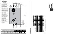


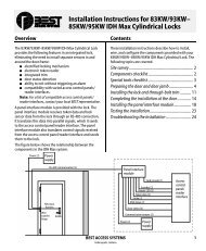

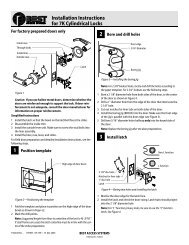


![B.A.S.I.S. G Service Manual [T63300] - Best Access Systems](https://img.yumpu.com/48375082/1/190x245/basis-g-service-manual-t63300-best-access-systems.jpg?quality=85)