Frame Relay - for Faster and More Efficient Data Communications ...
Frame Relay - for Faster and More Efficient Data Communications ... Frame Relay - for Faster and More Efficient Data Communications ...
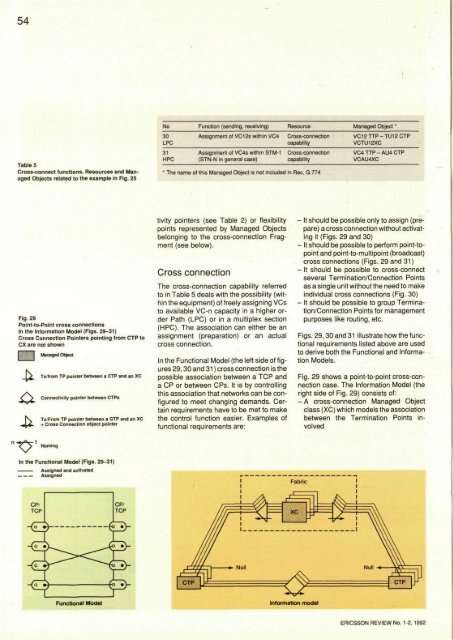
54Table 5Cross-connect functions, Resources and ManagedObjects related to the example in Fig. 25No30LPC31HPCFunction (sending, receiving)Assignment of VC12s within VC4ResourceCross-connectioncapabilityAssignment of VC4s within STM-1 Cross-connection(STN-N in general case)capability* The name of this Managed Object is not included in Rec. G.774Managed Object *VC12TTP-TU12CTPVCTU12XCVC4TTP-AU4CTPVCAU4XCFig. 29Point-to-Point cross connectionsIn the Information Model (Figs. 29-31)Cross Connection Pointers pointing from CTP toCX are not shownManaged ObjectTo/from TP pointer between a CTP and an XCConnectivity pointer between CTPsTo/From TP pointer between a GTP and an XCCross Connection object pointertivity pointers (see Table 2) or flexibilitypoints represented by Managed Objectsbelonging to the cross-connection Fragment(see below).Cross connectionThe cross-connection capability referredto in Table 5 deals with the possibility (withinthe equipment) of freely assigning VCsto available VC-n capacity in a higher orderPath (LPC) or in a multiplex section(HPC). The association can either be anassignment (preparation) or an actualcross connection.In the Functional Model (the left side of figures29,30 and 31) cross connection is thepossible association between a TCP anda CP or between CPs. It is by controllingthis association that networks can be configuredto meet changing demands. Certainrequirements have to be met to makethe control function easier. Examples offunctional requirements are:- It should be possible only to assign (prepare)a cross connection without activatingit (Figs. 29 and 30)- It should be possible to perform point-topointand point-to-multipoint (broadcast)cross connections (Figs. 29 and 31)- It should be possible to cross-connectseveral Termination/Connection Pointsas a single unit without the need to makeindividual cross connections (Fig. 30)- It should be possible to group Termination/ConnectionPoints for managementpurposes like routing, etc.Figs. 29,30 and 31 illustrate how the functionalrequirements listed above are usedto derive both the Functional and InformationModels.Fig. 29 shows a point-to-point cross-connectioncase. The Information Model (theright side of Fig. 29) consists of:-A cross-connection Managed Objectclass (XC) which models the associationbetween the Termination Points involvedNamingIn the Functional Model (Figs. 29-31)ERICSSON REVIEW No. 1-2, 1992
55Fig. 30Group Termination Point cross connection- To/from TP pointers, which are relationshipattributes belonging to the XC ManagedObject and pointing at the CTPs (orGTPs)-Connectivity pointers, which are relationshipattributes belonging to the CTPsand indicating which CTP is connectedto which CTP.In the example, four instances of this Objectclass represent the four point-to-pointcross connections. Three of the four to/-from TP pointers correspond to the threeactivated cross connections. In the fourth- only assigned - cross connection, theConnectivity pointers will be NULL to indicatea non-activated state.Fig. 30 shows cross connections betweendifferent groups of Termination/ConnectionPoints. In addition to the point-to-pointcase, the Information Model consists of:- A Group Termination Point ManagedObject class (GTP) which represents agroup of CTPs to be cross-connected asa single unit- A Cross Connection object pointer,which is a relationship attribute belongingto the GTP and pointing at the XCManaged Object- A "naming", which is a relationship attributebelonging to the GTP and pointing atthe CTPs that constitute the GTP.In the example, the three cross-connect-Fig. 31Broadcast cross connectionERICSSON REVIEW No. 1-2, 1992
- Page 6 and 7: 4Fig. 2Distributed computer environ
- Page 8 and 9: Fig. 7A company's data network shou
- Page 10 and 11: 8Fig. 11The frame format used for F
- Page 12 and 13: 10er (DE, Fig. 12) should be set to
- Page 14 and 15: Computerised System for QualityInsp
- Page 16 and 17: Box 1Code39, the first alphanumeric
- Page 18 and 19: 16Fig. 6Cable attenuation test at E
- Page 20 and 21: 18Fig. 9Installing the Dehlfi syste
- Page 22 and 23: Human Factors - A Key to ImprovedQu
- Page 24 and 25: 221 Use the user's model2 Introduce
- Page 26 and 27: 24Fig. 5Advanced Human Factors desi
- Page 28 and 29: Fig. 7User interface for PBX attend
- Page 30 and 31: Cell-voltage EqualisersSeries BMP 1
- Page 32 and 33: 30Box1CELL-VOLTAGE EQUALISER BMP 16
- Page 34 and 35: 32age, the faulty cell or the entir
- Page 36 and 37: In Search of Managed ObjectsWalter
- Page 38 and 39: Fig. 4The telecommunication network
- Page 40 and 41: Fig. 6Functional Model illustrating
- Page 42 and 43: 40Fig. 9Combination of layering and
- Page 44 and 45: 42Table 2Relationship between Funct
- Page 46 and 47: 44No1PPI2PPI3SLTTransport Function(
- Page 48 and 49: 46Table 4SDH functions, Resources a
- Page 50 and 51: The Managed Objects and their prope
- Page 52 and 53: 50Fig. 21Information Model of PDH d
- Page 54 and 55: Fig. 25Information Model of SDH mul
- Page 58: Fig. 32, leftCross-connect Fragment
54Table 5Cross-connect functions, Resources <strong>and</strong> ManagedObjects related to the example in Fig. 25No30LPC31HPCFunction (sending, receiving)Assignment of VC12s within VC4ResourceCross-connectioncapabilityAssignment of VC4s within STM-1 Cross-connection(STN-N in general case)capability* The name of this Managed Object is not included in Rec. G.774Managed Object *VC12TTP-TU12CTPVCTU12XCVC4TTP-AU4CTPVCAU4XCFig. 29Point-to-Point cross connectionsIn the In<strong>for</strong>mation Model (Figs. 29-31)Cross Connection Pointers pointing from CTP toCX are not shownManaged ObjectTo/from TP pointer between a CTP <strong>and</strong> an XCConnectivity pointer between CTPsTo/From TP pointer between a GTP <strong>and</strong> an XCCross Connection object pointertivity pointers (see Table 2) or flexibilitypoints represented by Managed Objectsbelonging to the cross-connection Fragment(see below).Cross connectionThe cross-connection capability referredto in Table 5 deals with the possibility (withinthe equipment) of freely assigning VCsto available VC-n capacity in a higher orderPath (LPC) or in a multiplex section(HPC). The association can either be anassignment (preparation) or an actualcross connection.In the Functional Model (the left side of figures29,30 <strong>and</strong> 31) cross connection is thepossible association between a TCP <strong>and</strong>a CP or between CPs. It is by controllingthis association that networks can be configuredto meet changing dem<strong>and</strong>s. Certainrequirements have to be met to makethe control function easier. Examples offunctional requirements are:- It should be possible only to assign (prepare)a cross connection without activatingit (Figs. 29 <strong>and</strong> 30)- It should be possible to per<strong>for</strong>m point-topoint<strong>and</strong> point-to-multipoint (broadcast)cross connections (Figs. 29 <strong>and</strong> 31)- It should be possible to cross-connectseveral Termination/Connection Pointsas a single unit without the need to makeindividual cross connections (Fig. 30)- It should be possible to group Termination/ConnectionPoints <strong>for</strong> managementpurposes like routing, etc.Figs. 29,30 <strong>and</strong> 31 illustrate how the functionalrequirements listed above are usedto derive both the Functional <strong>and</strong> In<strong>for</strong>mationModels.Fig. 29 shows a point-to-point cross-connectioncase. The In<strong>for</strong>mation Model (theright side of Fig. 29) consists of:-A cross-connection Managed Objectclass (XC) which models the associationbetween the Termination Points involvedNamingIn the Functional Model (Figs. 29-31)ERICSSON REVIEW No. 1-2, 1992


