

Frame Relay - for Faster and More Efficient Data Communications ...
Frame Relay - for Faster and More Efficient Data Communications ...
Frame Relay - for Faster and More Efficient Data Communications ...
- No tags were found...

Create successful ePaper yourself
Turn your PDF publications into a flip-book with our unique Google optimized e-Paper software.
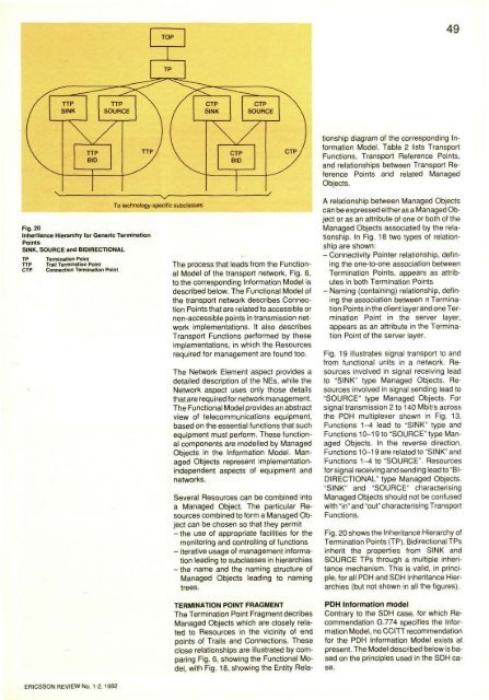
49TERMINATION POINT FRAGMENTThe Termination Point Fragment decribesManaged Objects which are closely relatedto Resources in the vicinity of endpoints of Trails <strong>and</strong> Connections. Theseclose relationships are illustrated by comparingFig. 6, showing the Functional Model,with Fig. 18, showing the Entity Relationshipdiagram of the corresponding In<strong>for</strong>mationModel. Table 2 lists TransportFunctions, Transport Reference Points,<strong>and</strong> relationships between Transport ReferencePoints <strong>and</strong> related ManagedObjects.Fig. 20Inheritance Hierarchy <strong>for</strong> Generic TerminationPointsSINK, SOURCE <strong>and</strong> BIDIRECTIONALTPTTPCTPTermination PointTrail Termination PointConnection Termination PointThe process that leads from the FunctionalModel of the transport network, Fig. 6,to the corresponding In<strong>for</strong>mation Model isdescribed below. The Functional Model ofthe transport network describes ConnectionPoints that are related to accessible ornon-accessible points in transmission networkimplementations. It also describesTransport Functions per<strong>for</strong>med by theseimplementations, in which the Resourcesrequired <strong>for</strong> management are found too.The Network Element aspect provides adetailed description of the NEs, while theNetwork aspect uses only those detailsthat are required <strong>for</strong> network management.The Functional Model provides an abstractview of telecommunications equipment,based on the essential functions that suchequipment must per<strong>for</strong>m. These functionalcomponents are modelled by ManagedObjects in the In<strong>for</strong>mation Model. ManagedObjects represent implementationindependentaspects of equipment <strong>and</strong>networks.Several Resources can be combined intoa Managed Object. The particular Resourcescombined to <strong>for</strong>m a Managed Objectcan be chosen so that they permit- the use of appropriate facilities <strong>for</strong> themonitoring <strong>and</strong> controlling of functions- iterative usage of management in<strong>for</strong>mationleading to subclasses in hierarchies-the name <strong>and</strong> the naming structure ofManaged Objects leading to namingtrees.A relationship between Managed Objectscan be expressed either as a Managed Objector as an attribute of one or both of theManaged Objects associated by the relationship.In Fig. 18 two types of relationshipare shown:- Connectivity Pointer relationship, definingthe one-to-one association betweenTermination Points, appears as attributesin both Termination Points- Naming (containing) relationship, definingthe association between n TerminationPoints in the client layer <strong>and</strong> one TerminationPoint in the server layer,appears as an attribute in the TerminationPoint of the server layer.Fig. 19 illustrates signal transport to <strong>and</strong>from functional units in a network. Resourcesinvolved in signal receiving leadto "SINK" type Managed Objects. Resourcesinvolved in signal sending lead to"SOURCE" type Managed Objects. Forsignal transmission 2 to 140 Mbit/s acrossthe PDH multiplexer shown in Fig. 13,Functions 1-4 lead to "SINK" type <strong>and</strong>Functions 10-19 to "SOURCE" type ManagedObjects. In the reverse direction,Functions 10-19 are related to "SINK" <strong>and</strong>Functions 1-4 to "SOURCE". Resources<strong>for</strong> signal receiving <strong>and</strong> sending lead to "BIDIRECTIONAL" type Managed Objects."SINK" <strong>and</strong> "SOURCE" characterisingManaged Objects should not be confusedwith "in" <strong>and</strong> "out" characterising TransportFunctions.Fig. 20 shows the Inheritance Hierarchy ofTermination Points (TP). Bidirectional TPsinherit the properties from SINK <strong>and</strong>SOURCE TPs through a multiple inheritancemechanism. This is valid, in principle,<strong>for</strong> all PDH <strong>and</strong> SDH Inheritance Hierarchies(but not shown in all the figures).PDH In<strong>for</strong>mation modelContrary to the SDH case, <strong>for</strong> which RecommendationG.774 specifies the In<strong>for</strong>mationModel, no CCITT recommendation<strong>for</strong> the PDH In<strong>for</strong>mation Model exists atpresent. The Model described below is basedon the principles used in the SDH case.ERICSSON REVIEW No. 1-2, 1992


