Frame Relay - for Faster and More Efficient Data Communications ...
Frame Relay - for Faster and More Efficient Data Communications ... Frame Relay - for Faster and More Efficient Data Communications ...
Fig. 6Functional Model illustrating the use of TransportFunctionsA Connection can be a Link Connection, a Sub-Network Connection or a Matrix connectionATCLCAPCPTCPClient-to-server adaptationTrail TerminationConnectionLink ConnectionAccess PointConnection PointTermination Connection PointFig 7Simplified Functional Model illustrating the useof Transport FunctionsGeneric Transport Network Architecture."The basic elements of this model are- Transport Entities, such as Link Connection(LC), Sub-Network Connection(SNC) and Trail. Transport Entitiestransfer information transparently- Transport Processing Functions, suchas Adaptation (A) and Trail Termination(T). Transport Processing Functionsprocess the transferred information-Transport Reference Points, such asConnection Points (CP), TerminationConnection Points (TCP) and AccessPoints (AP).Some of the Transport Processing Functionsand Transport Entities are defined asfollows:-The Transport Entity "Trail" is responsiblefor the transfer of characteristic information(signals with specified datarates and formats) between the AccessPoints to a layer (AP). A Trail containsnear-end and far-end Trail Terminationsand one or several Network Connections- The Transport Entity "Network Connection"is responsible for the transfer of informationbetween Termination Connec-ERICSSON REVIEW No. 1-2, 1992
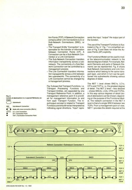
39Fig. 8Levels of abstraction in a Layered Network; exampleSubnetworktion Points (TCP). A Network Connectioncontains either Link Connections (LC) orSub-Network Connections (SNC), orboth- The Transport Entity "Connection" is responsiblefor the transfer of informationbetween Connection Points (CP). AConnection can be a Sub-Network Connectionor a Link Connection- The Sub-Network Connection transfersinformation transparently across a subnetwork.The connectivity of a Sub-NetworkConnection can be controlled by amanagement process- The Link Connection transfers informationtransparently across a link betweentwo subnetworks. The connectivity of aLink Connection cannot be changed bya management process.Fig. 5 shows that Transport Functions, i.e.Transport Processing Functions andTransport Entities, are separated by oneTransport Reference Point. In addition, amanagement reference point S is providedfor management information to andfrom each Transport Function. The input/outputconcept is related to TransportFunctions and should not be interpreted asindicating signal directions. "Input" representsthe input, "output" the output part ofthe function.The use of the Transport Functions is illustratedin Fig. 6." Fig. 7 is a simplified versionof Fig. 6 and does not show the AccessPoints (AP) explicitly.The Functional Model can be used to modelthe telecommunication network to thedesired degree of detail. Forexample, NetworkElements and parts of Network Elementscan be represented. Fig. 8 showsSub-Network Connections and Link Connectionswhich belong to the same transportlayer, and which in turn can be partitionedinto subnetworks showing variousdegrees of detail.The NET 1 level shows SNC1s, LC1s,CP1 s and TCP1 s, i.e. the greatest degreeof detail. The NET 2 level - less detailed- shows SNC2s, LC2s, CP2s and TCP2s.In this way various degrees of detail (levelsof abstraction) can be chosen, dependingon the purpose of the Functional Model.The network connection in the NET 4level is that of a single SNC4 between twoTCPs. From a management point of view,NET 1 provides the details required at theERICSSON REVIEW No. 1-2, 1992
- Page 1: ERICSSONREVIEW1-21992Frame Relay -
- Page 4 and 5: ERICSSON REVIEWBO HEDFORSPublisher
- Page 6 and 7: 4Fig. 2Distributed computer environ
- Page 8 and 9: Fig. 7A company's data network shou
- Page 10 and 11: 8Fig. 11The frame format used for F
- Page 12 and 13: 10er (DE, Fig. 12) should be set to
- Page 14 and 15: Computerised System for QualityInsp
- Page 16 and 17: Box 1Code39, the first alphanumeric
- Page 18 and 19: 16Fig. 6Cable attenuation test at E
- Page 20 and 21: 18Fig. 9Installing the Dehlfi syste
- Page 22 and 23: Human Factors - A Key to ImprovedQu
- Page 24 and 25: 221 Use the user's model2 Introduce
- Page 26 and 27: 24Fig. 5Advanced Human Factors desi
- Page 28 and 29: Fig. 7User interface for PBX attend
- Page 30 and 31: Cell-voltage EqualisersSeries BMP 1
- Page 32 and 33: 30Box1CELL-VOLTAGE EQUALISER BMP 16
- Page 34 and 35: 32age, the faulty cell or the entir
- Page 36 and 37: In Search of Managed ObjectsWalter
- Page 38 and 39: Fig. 4The telecommunication network
- Page 42 and 43: 40Fig. 9Combination of layering and
- Page 44 and 45: 42Table 2Relationship between Funct
- Page 46 and 47: 44No1PPI2PPI3SLTTransport Function(
- Page 48 and 49: 46Table 4SDH functions, Resources a
- Page 50 and 51: The Managed Objects and their prope
- Page 52 and 53: 50Fig. 21Information Model of PDH d
- Page 54 and 55: Fig. 25Information Model of SDH mul
- Page 56 and 57: 54Table 5Cross-connect functions, R
- Page 58: Fig. 32, leftCross-connect Fragment
39Fig. 8Levels of abstraction in a Layered Network; exampleSubnetworktion Points (TCP). A Network Connectioncontains either Link Connections (LC) orSub-Network Connections (SNC), orboth- The Transport Entity "Connection" is responsible<strong>for</strong> the transfer of in<strong>for</strong>mationbetween Connection Points (CP). AConnection can be a Sub-Network Connectionor a Link Connection- The Sub-Network Connection transfersin<strong>for</strong>mation transparently across a subnetwork.The connectivity of a Sub-NetworkConnection can be controlled by amanagement process- The Link Connection transfers in<strong>for</strong>mationtransparently across a link betweentwo subnetworks. The connectivity of aLink Connection cannot be changed bya management process.Fig. 5 shows that Transport Functions, i.e.Transport Processing Functions <strong>and</strong>Transport Entities, are separated by oneTransport Reference Point. In addition, amanagement reference point S is provided<strong>for</strong> management in<strong>for</strong>mation to <strong>and</strong>from each Transport Function. The input/outputconcept is related to TransportFunctions <strong>and</strong> should not be interpreted asindicating signal directions. "Input" representsthe input, "output" the output part ofthe function.The use of the Transport Functions is illustratedin Fig. 6." Fig. 7 is a simplified versionof Fig. 6 <strong>and</strong> does not show the AccessPoints (AP) explicitly.The Functional Model can be used to modelthe telecommunication network to thedesired degree of detail. Forexample, NetworkElements <strong>and</strong> parts of Network Elementscan be represented. Fig. 8 showsSub-Network Connections <strong>and</strong> Link Connectionswhich belong to the same transportlayer, <strong>and</strong> which in turn can be partitionedinto subnetworks showing variousdegrees of detail.The NET 1 level shows SNC1s, LC1s,CP1 s <strong>and</strong> TCP1 s, i.e. the greatest degreeof detail. The NET 2 level - less detailed- shows SNC2s, LC2s, CP2s <strong>and</strong> TCP2s.In this way various degrees of detail (levelsof abstraction) can be chosen, dependingon the purpose of the Functional Model.The network connection in the NET 4level is that of a single SNC4 between twoTCPs. From a management point of view,NET 1 provides the details required at theERICSSON REVIEW No. 1-2, 1992


