cover RPD15F,25F.qxp - Chamberlain
cover RPD15F,25F.qxp - Chamberlain
cover RPD15F,25F.qxp - Chamberlain
- No tags were found...

You also want an ePaper? Increase the reach of your titles
YUMPU automatically turns print PDFs into web optimized ePapers that Google loves.
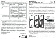
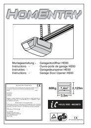
2. WiringMainsLNgreen/yellowbluebrownAdjustment screws forlimit switch systemen-4blackMotorcablesingle-pole switchAntennaDEFAULT SETTINGThe limits of the shutter motor have been set to a short length of travel (small window) and must be merely adjusted to suit actual requirements.See under Point 3: Setting the limitsThe radio remote control (hand-held transmitter) has already been programmed at the factory. Should it operate in the reverse direction i.e. buttonfor upward direction moves shutter downwards, this can be remedied.See under: Programming first radio remote control.3. Setting the limits “Open” and “Closed” position1+ = stops later– = stops earlier24. FASTEN SHUTTER ARMOURING (SLATS) TOSHAFT.Limit at bottom is now set. If necessary make final adjustment withadjustment screw.Allow drive to run upwards. If it switches off too earlythe bottom adjusting screw must be adjusted in the plus direction.Each full turn of this screw extends the travel path by about 40° of oneturn of the motor. The motor should stop just a few inches below thewindow frame. If not the adjusting screw should be adjusted in theminus direction. After this the drive must be driven back a little and thenup again to check the result.Arrows show thedirection the shutter willcoil up with the driveinstalled left- or righthand sideIt is possible that the drive will switch itself off after several trips becauseit has reached a temperature which is too high. Howevere after 15 – 20minutes cooling time it will be ready to operate again.Please note that the limit switches of the drive only functionproperly if the drive has been installed correctly and is completelywithin the shaft.The bottom adjusting screw is always for the upper limit and the upper isalways for the lower limit, no matter whether the motor is pushed intothe shaft from the right or the left.My roller shutter box is:A: A left-handed installation. I look into the box and the limit switch ofthe motor is on the left (see Fig. L1)White = Limit switch AT BOTTOMRed = Limit switch AT TOPB: A right-handed installation. I look into the box and the limit switch ofthe motor is on the right (see Fig. L2)Red = Limit switch AT BOTTOMWhite = Limit switch AT TOPPLEASE READ THROUGH THE FOLLOWING INSTRUCTIONSCAREFULLY BEFORE SETTING THE LIMITS.Press the DOWN / UP button (remote control or switch) and let theshutter drive move in a downward direction until it cuts off automaticallyand then (and only then!) ......Advice: In order to fix the roller shutter hangers to the shaft,ONLY use short fixing screws. If the screws are too long damagemay occur to the motor. The recommended fixing method for thehangers is without screws by means of spring band loops (whichare hooked on).