MicroKom® hi.flex FINISH BORING SYSTEM - Komet
MicroKom® hi.flex FINISH BORING SYSTEM - Komet
MicroKom® hi.flex FINISH BORING SYSTEM - Komet

You also want an ePaper? Increase the reach of your titles
YUMPU automatically turns print PDFs into web optimized ePapers that Google loves.
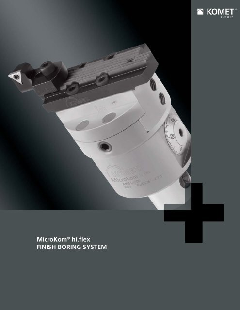
MicroKom ® <strong>hi</strong>.<strong>flex</strong><strong>FINISH</strong> <strong>BORING</strong> <strong>SYSTEM</strong>
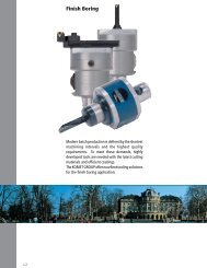
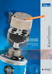
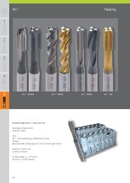
Fine adjustment system for diameters 0.236“ to 4.921“KOMET Group extended its MicroKom ® micro adjustableboring product line with the new M05 <strong>hi</strong>.<strong>flex</strong> system. Theunique finish boring system is specially designed for <strong>hi</strong>gh<strong>flex</strong>ibility and covers the diameter ranges from 0.236” to4.921” with just one adjustable boring head. The availabilityof various boring bars and the new intelligent adapter designcontribute to t<strong>hi</strong>s wide diameter range.The adjustable head offers an adjustment accuracy of0.0004” per graduation on an easy-to-read scale and0.00008” from a vernier with a total adjustment path ofup to 0.197”. The system is balanced in zero position andprovides an internal coolant supply directly on to the cuttingedge throughout the entire cutting diameter range.The standard set includes four boring bars for diameters0.236“ to 0.984“. According to the individual combination,a serrated body, a bridge and two different holders forinserts provide for cutting diameters up to 4.921“.The MicroKom ® <strong>hi</strong>.<strong>flex</strong> is compatible with existing ABS ®and cylindrical shank fine boring components. The set canbe extended with standard boring tools and UniTurn ®products, for w<strong>hi</strong>ch the turning range starts at 0.020“.Variable overhang lengths and a single key for clamping,adjusting and mounting bridges and insert holders illustratehow easy the new system is to operate.Ø 0.236“ – 0.984“ Ø 0.984“ - 2.480“ Ø 2.480“ – 3.661“ Ø 3.543“ – 4.921“Dia. range covered with4 different boring barsDia. range covered withserrated body and 2 differentinsert holdersDia. range covered wit<strong>hi</strong>nsert holderDia. range covered withbridge and insert holder2
Finish boring kit with inch adjustmentFinish boring kit Ø 0.236“ - 4.921“Order No. M05 00610Contents of caseOrder No. Qty. Description M05 01600 1 Micro-adjustable head M05 20600 1 Insert holder Ø 0.984“ - 1.732“ M05 20650 1 Insert holder Ø 1.732“ - 4.921“ M05 80600 1 Bridge M05 90600 1 Serrated body M05 90500.11 1 Packing piece B05 20600 1 Boring bar Ø 0.236“ - 0.315“ B05 20620 1 Boring bar Ø 0.315“ - 0.472“ B05 20660 1 Boring bar Ø 0.472“ - 0.709“ B05 20720 1 Boring bar Ø 0.709“ - 0.984“A5210150 orA52103501 ABS 50 CAT 50 or ABS50 CAT 40 Adapter 1805010040 1 Allen key SW4L05 01110 1 Flag key 5IPL05 01120 1 Flag key 6IPL05 01240 1 Flag key 8IP5501105016 5 Cylindrical screw M5×16W57 04140.0260 4 Insert BK60W57 14140.0460 4 Insert BK60W00 04120.0164 2 Insert BK643
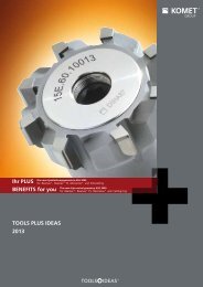
Variable OptionsOnly 9 tool componentscovering diameters 0.236“ – 4.921“Boring barB05 20600Ø 0.236“- 0.315“B05 20620Ø 0.315“- 0.472“Micro-adjustable headM05 01600B05 20660B05 20720Ø 0.472“- 0.709“Ø 0.709“- 0.984“Serrated bodyM05 90600Insert holderM05 20600Ø 0.984“-1.457“adjustment with slide:Ø 1.457“- 1.732“Insert holderM05 20650Ø 1.732“- 2.205“adjustment with slide:Ø 2.205“- 2.480“BridgeM05 80600Ø 2.480“- 3.268“adjustment with slide:Ø 3.268“-3.661“Ø 3.543“- 4.724“bridge rotated 180°:Ø 3.740“- 4.921“4
Mac<strong>hi</strong>neConnectionCoolant SupplyCentralAdjustableRotatingToolABS ® ABS ®ToolConnectionToolConnectionCylindricalshankMicro-adjustable boring head with ABS ® connectionwith ABS ® and cylindrical tool adapterLL1ABS50d2d1AdjustmentClamping screwDIN913ABSOrder No. d d1 d2 S L L1 Order No.DescriptionABS50/16 M05 01600 50 2.362 ABS32 0.197 2.638 1.575 2.70The micro-adjustable boring head is balanced in the zero position.Adjustment must be in line with cutting parameters and spindle speed.5505108116M8×1×16Replacement PartClamping screwDIN913Order No.Description5505108008M8×8Gripper screwOrder No.DescriptionN00 02061ABS32-F1Features :• Diameter range 0.020“- 4.921“with existing KOMET standard tools• Large adjustment range from -0.020 to + 0.394“ on dia.• Easy to use• Adjustment per graduation = Ø 0.0004“• Adjustment accuracy Ø 0.00008“ with vernier• Easy-to-read scale• Existing ABS32 tools can be used• Internal coolant supply over entire range• ABS32 spindle connection and 0.630“cylindrical shank• Can be adapted for any mac<strong>hi</strong>ne tool with standard tool adapters• Head diameter: 2.362“Important: See page 10 for more application details and safety notes!5
Boring bar Ø 0.236“ – 0.709“L / D Through hole Blind hole Slanted Surface Cross Hole Boring Backwards HRC > 54 HRC > 54Through Hole Blind HoleVibrationDampening3.5×D § § $ $ X § § X§ <strong>hi</strong>ghly recommended $ recommended & may be suitable X not recommendedwith cylindrical shank = 90° R.H. cuttingL1L2NRdfD minDminBasic RecommendationInsertW00 W30 W57Order No. d L1 L2 N f Order No. ISO Insert DescriptionSizeforWorkpiece MaterialP M K N S HReplacement PartClamping screw TORX PLUSOrder No.DescriptionOrder No.DescriptionW00 04120.01640.236 B05 20600 0.630 2.823 1.575 0.872 0.118 0.14W00 04120.0121WOHX02T001EL-G12 BK64WOHX02T001FL-G12 K10N00 56011S/M1.8×2.9-5IP3.4 in-lbsL05 008005IPW57 04140.02600.315 B05 20620 0.630 3.047 1.575 1.102 0.157 0.15W57 04120.02230.472 B05 20660W30 04990.02400.630 3.472 1.575 1.654 0.236 0.19W30 04060.036110W57 14140.04600.709 B05 20720W57 14120.04230.630 3.937 1.575 2.362 0.354 0.31W30 14990.0440W30 14060.046110TOGX06T102EN-14 BK60TOGX06T102FN-12 K10TOGX06T102TN CBN40TOHX06T103EL-G06 BK6110TOGX090204EN-14 BK60TOGX090204FN-12 K10TOGX090204TN CBN40TOHX090204EL-G06 BK6110
Cutting RecommendationsGuideline for finish boring withMicroKom ® <strong>hi</strong>.<strong>flex</strong> Fine boring systemMaterial group1.02.02.13.04.04.15.05.16.0PS6.1MTensile Strength (lbf/ln 2 )7250072500 -130000130000>1300005800087000130000180250Stainless steel:martensitic/ferritic400 seriesGrey cast iron420403No 35 BNo 50 BAlloy grey castiron A436 Type 2660 790 390.002 .002 .000.004 .004 .002.006 .006 .0030.315-0.469W57 04140.0232W30 04120.0238W30 04990.0255W30 04990.0257TOGX06T102EN-14 CK32TOGX06T102EL-G12 CK38TOGX06T102FN PCD55TOGX06T102FN CBN57only GG259.1 9.0K87000130230Nodular cast ironferritic 60-40-18Nodular cast ironferritic / pearlitic80-55-06590 590.002 .002.003 .003.006 .0060.472-0.984W57 14140.0432 TOGX090204EN-14 CK32W30 14120.0238 TOGX090202EL-G12 CK38W30 14990.0455 TOGX090204FN PCD55W30 14990.0457 TOGX090204FN CBN57only GG2512.1 12.0 10.2 10.1 10.08700025020030090100Nodular cast ironpearliticMalleable cast ironAlloyed nodularcast ironVermicular castironCopper alloy,brass, Lead alloy,Bronze,Lead bronze:good cutCopper alloy,Brass, Bronze:average cut100-70-0370003A43D2UNS C36000980 1310 390 460 520.002 .001 .001 .001 .002.003 .002 .004 .003 .003.006 .003 .006 .005 .006D0.236-0.311W57Order No.size–For better surface finishInsertforW30Workpiece MaterialW30 PCDISO Insert Description P M K N S H13.013.1N6075Wroughtaluminum alloyAluminum alloy:Si content 10% A360.2Hardened steel< 45 HRCHardened steel> 45 HRCPlease see page 10 for more application details and safety notes!980390300.002––.003.002.002.005.003.0030.472-0.984W57 14140.0432 TOGX090204EN-14 CK32W30 14060.046110 TOGX090204EL-G06 BK6110W30 14200.0421 TOGX090204FL-G20 K10W30 14990.0455 TOGX090204FN PCD557
Basic body / Insert holder Ø 0.984“ – 3.661“L / D Through hole Blind hole Slanted Surface Cross Hole Boring Backwards HRC > 54HRC > 54VibrationThrough Hole Blind HoleDampening< 2.5×D § § $ $ X § § X§ <strong>hi</strong>ghly recommended $ recommended & may be suitable X not recommendedØ 0.984“ – 2.480“d1Basic bodydL2ND = Ø 0.983“- 1.732“D = Ø 1.732“- 2.480“L Ø 2.480“ – 3.661“3.169D = Ø 2.480“- 3.661“ Packing pieceM05 90500.11to divert coolantBasic bodyLocation screwReplacement partsCup springOrder No. d d1 N L L1 Order No.DescriptionM05 90600 0.630 0.748 2.559 3.484 2.028 0.365501105016M5×16 ISO4762Order No.Description5677110053A12.5Ø6.2×0.35Delivery: Serrated body complete with location screw and cup spring.Insert Holder Basic Recommendation Replacement PartInsertforWorkpiece MaterialClamping screw TORX PLUS-12 -14 -G06D Order No. Order No.SizeISO Insert Description P M K N S H Order No.DescriptionOrder No.Description0.983 - 1.732 M05 20600 0.042W57 04140.0260 TOGX06T102EN-14 BK60W30 04060.0361 TOHX06T103EL-G06 BK61W57 04120.0223 TOGX06T102FN-12 K10N00 56031S/M2×4.9-6IP5.5 in-lbsL05 008106IPW57 14140.0460 TOGX090204EN-14 BK601.732 - 3.661 M05 20650 0.057 W30 14060.0461 TOHX090204EL-G06 BK61W57 14120.0423 TOGX090204FN-12 K10Delivery: Insert holder complete with clamping screw.Please order inserts and Torx Plus screw driver separately.8N00 56111S/M2.6×6.2-8IP11.3 in-lbsL05 008308IP
Cutting RecommendationsGuideline for finish boring withMicroKom ® <strong>hi</strong>.<strong>flex</strong> Fine boring systemMaterial group1.02.0Tensile Strength (lbf/ln 2 )7250072500 -130000Hardness HBMaterialUnalloyed steelLow alloy steelMaterial exampleAISI / SAEA570.361213A573.81512010555115Cutting speedv c, ft/min980820MaximumFeedratef, in/revØ 0.984 - 1.732.003.003Ø 1.732 - 3.661.004.005Alternative InsertD0.984 - 1.732For better c<strong>hi</strong>p controlInsertforW30 W57Workpiece MaterialOrder No. ISO Insert Description P M K N S HsizeW30 04120.3232W30 04120.3060W57 04120.0223TOHX06T102EL-US12 CK32TOHX06T100EL-G12 BK60TOGX06T102FN-12 K102.13.0P130000Lead alloy12L13High alloy steelheat resistant4140structural, heat1064treated, nitride steels980790.004.003.006.0041.732 - 3.661W30 14120.3232W30 14120.3060W57 14120.0423TOHX090202EL-US12 CK32TOHX090200EL-G12 BK60TOGX090204FN-12 K106.0 5.1 5.0 4.1 4.0S>1300005800087000250Tool steelHSSSpecial alloy:Inconel, Hastelloy,Nimonic, etc.Titanium,Titanium alloyStainless steel:austenitic300 seriesH13H21Inconel ® 718Nimonic ® 80AAMS R54520304L316660 100 160 390 660.003 .002 .002 .002 .002.004 .003 .003 .003 .004DW57Order No.sizeFor better wear resistanceInsertforW30PCDWorkpiece MaterialW30 CBNISO Insert Description P M K N S H8.0 7.0 6.1M130000180Stainless steelStainless steel:martensitic/ferritic400 seriesGrey cast iron630420403No 35 BNo 50 B790 390 590.006 .002 .002.008 .004 .0040.984 - 1.732W57 04140.0232W30 04990.0355W30 04990.0357TOGX06T102EN-14 CK32TOGX06T103FN PCD55TOGX06T103TN CBN579.1 9.0 8.1K87000250130230Alloy grey castiron A436 Type 2Nodular cast ironferritic 60-40-18Nodular cast ironferritic / pearlitic80-55-06590 590 660.004 .004 .006.006 .006 .0081.732 - 3.661W30 14120.3232W30 14120.3060W57 14120.0423TOHX090202EL-US12 CK32TOHX090200EL-G12 BK60TOGX090204FN-12 K1010.010.110.212.012.113.013.114.015.016.0NH87000203000261000250200300901006075100Nodular cast ironpearliticMalleable cast ironAlloyed nodularcast ironVermicular castironCopper alloy,brass, Lead alloy,Bronze,Lead bronze:good cutCopper alloy,Brass, Bronze:average cutWroughtaluminum alloyAluminum alloy:Si content 10% A360.2Hardened steel< 45 HRCHardened steel> 45 HRCPlease see page 10 for more application details and safety notes!52046039098089016401150820390300.004.004.004.004.004.003.004.004.003.002.006.006.006.006.006.005.006.006.003.003D0.984 - 1.7321.732 - 3.661W57Order No.sizeW30 04120.3160W30 04990.0355W30 04990.0357W30 04990.0240W30 14120.3160W30 14120.3060W57 14120.0423W30 14990.0440For better surface finishInsertforW30PCDWorkpiece MaterialW30 CBNISO Insert Description P M K N S HTOHX06T102EL-UF12 BK60TOGX06T103FN PCD55TOGX06T103TN CBN57TOGX06T103TN CBN40TOHX090202EL-UF12 BK60TOHX090200EL-G12 BK60TOGX090204FN-12 K10TOGX090204TN CBN409
Cutting RecommendationsGuideline for finish boring withMicroKom ® <strong>hi</strong>.<strong>flex</strong> Fine boring systemMaterial group1.02.02.13.0PTensile Strength (lbf/ln 2 )7250072500 -130000130000Hardness HBMaterialUnalloyed steelLow alloy steelLead alloyMaterial exampleAISI / SAEA570.361213A573.8151201055511512L13High alloy steelheat resistant4140structural, heat1064treated, nitride steelsCutting speedv c, ft/min980820980790MaximumFeedratef, in/revØ 3.543 - 4.921.004.005.006.004Alternative InsertD3.543 - 4.921For better c<strong>hi</strong>p controlInsertforW30 W57Workpiece MaterialOrder No. ISO Insert Description P M K N S HsizeW30 14120.3232W30 14120.3060W57 14120.0423TOHX090202EL-US12 CK32TOHX090200EL-G12 BK60TOGX090204FN-12 K106.0 5.1 5.0 4.1 4.0S87000 58000>130000250Tool steelHSSSpecial alloy:Inconel, Hastelloy,Nimonic, etc.Titanium,Titanium alloyStainless steel:austenitic300 seriesH13H21Inconel ® 718Nimonic ® 80AAMS R54520304L316660 100 160 390 660.004 .003 .003 .003 .004DW57Order No.sizeFor better wear resistanceInsertforW30PCDWorkpiece MaterialW30 CBNISO Insert Description P M K N S H6.1M130000180250Stainless steel:martensitic/ferritic400 seriesGrey cast iron420403No 35 BNo 50 BAlloy grey castiron A436 Type 2660 790 390.008 .008 .0043.543 - 4.921W30 14120.3232W30 14120.3060W57 14120.0423TOHX090202EL-US12 CK32TOHX090200EL-G12 BK60TOGX090204FN-12 K109.1 9.0K87000130230Nodular cast ironferritic 60-40-18Nodular cast ironferritic / pearlitic80-55-06590 590.006 .00612.0 10.2 10.1 10.08700025020030090Nodular cast ironpearliticMalleable cast ironAlloyed nodularcast ironVermicular castironCopper alloy,brass, Lead alloy,Bronze,Lead bronze:good cut100-70-0370003A43D2UNS C36000980 390 460 520.006 .006 .006 .006DW57Order No.sizeFor better surface finishInsertforW30PCDWorkpiece MaterialW30 CBNISO Insert Description P M K N S H12.1100Copper alloy,Brass, Bronze:average cut890.00613.013.114.0N6075100Wroughtaluminum alloyAluminum alloy:Si content 10% A360.21640980820.005.006.0063.543 - 4.921W30 14120.3160W30 14120.3060W57 14120.0423W30 14990.0440TOHX090202EL-UF12 BK60TOHX090200EL-G12 BK60TOGX090204FN-12 K10TOGX090204TN CBN4015.0203000Hardened steel< 45 HRC390.00316.0H261000Hardened steel> 45 HRCPlease see page 10 for more application details and safety notes!300.00311
Boring Bar AdapterAdapterwith cylindrical tool locationfor clamping vibration dampened fine boring barsOptional EquipmentCompass CatalogReference PageL1LØ 0.220” / 0.272” 4.28d2 d d1Ø 0.354” / 0.433” 4.28Ø 0.512” – 1.024” 4.28Assembly partsClamping screwDIN913Order No. d d1 d2 L L1Description Order No.M05 90200 0.236 1.220 – 0.630 – 0.25 M8×10 55051 08010M05 90210 0.315 1.220 – 0.630 – 0.26 M8×10 55051 08010M05 90220 0.394 1.220 1.811 0.590 0.984 0.34 M8×10 55051 08010M05 90230 0.472 1.220 1.811 0.590 0.984 0.32 M8×10 55051 08010M05 90240 0.630 1.220 1.811 0.787 1.181 0.32 M8×8 55051 08008Supplies include: Adapter complete.Instruction for adapter M05 90240Please note:Before tightening the holding screw , center the adapter with shank Ø for the boring bar on the micro-adjustablehead.12
Optional EquipmentMounting bridgefor O.D. mac<strong>hi</strong>ning Ø 0.197” – 2.756”Setting the diameterUpper scale• Position the mounting bridge on the micro-adjustable head.• Set the coarse position on the upper scale, tighten screw .Important note: check position of screw forrequired Ø range!Ø 0.197” – 1.338” Ø 1.299” – 1.732” Ø 1.693” – 2.756”Front scalePositioningmarkFine adjustmentscale• Align the front scale for the mounting bridge with the positioningmark on the adjustable head, tighten the pull stud .• Carry out fine adjustment on the setting device using the scaleon the micro-adjustable head.2.7562.2830.630max. 1.457max. 1.378max. 4.1021.496Basic RecommendationInsertforWorkpiece MaterialClampingscrewReplacement PartsTORX PLUSCylindricalscrew DW30 -12 -14Order No. Order No. ISO Insert Description P M K N S H Order No.sizeDescriptionOrder No.DescriptionOrder No.Description0.197“ –2.756“M05 90300 0.014W57 14140.0460W30 14060.0461W57 14120.0423TOGX090204EN-14 BK60TOHX090204EL-G06 BK61TOGX090204FN-12 K10§§§§N00 56111S/M2.6×6.2-8IP11.3 in-lbsL05 008308IP55011 05030M5×30Supplies include: Mounting bridge with assembly parts.Please order inserts and accessories separately.13
Notes
Notes15
KOMET of AMERICA, Inc.2050 Mitchell Blvd.Schaumburg, IL 60193-4544MAIN OFFICE: 847/923-8400FAX: 1-800-865-6638CUSTOMER SERVICE/ORDER ENTRY: 847/923-8480E-MAIL: customerservice@komet.comINTERNET: www.komet.comKOMET of AMERICA, Inc.Detroit Branch6804 19½ Mile RoadSterling Heights, MI 48314-1404MAIN OFFICE: 586/997-0855FAX: 586/997-0859KOMET de MEXICO, S. DE R. L.Acceso “A” No. 110Parque Ind. JuricaQuerétaro, QRO. 76120MEXICOTELEFONO: (52) (442) 218-2544FAX: (52) (442) 218-2077www.komet.comPRESENTED BY:399 02 982 29-2T-10/08 Printed in USA · © 2008 KOMET of America. We reserve the right to make modifications.