User's Manual - Minarik
User's Manual - Minarik
User's Manual - Minarik
- No tags were found...
You also want an ePaper? Increase the reach of your titles
YUMPU automatically turns print PDFs into web optimized ePapers that Google loves.
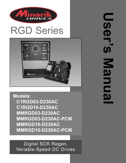
250-0249r6.qxp 10/1/2004 9:05 AM Page aRGD SeriesModels:C1RGD03-D230ACC1RGD10-D230ACMMRGD03-D230ACMMRGD03-D230AC-PCMMMRGD10-D230ACMMRGD10-D230AC-PCMUser’s <strong>Manual</strong>Digital SCR Regen,Variable-Speed DC Drives
250-0249r6.qxp 10/1/2004 9:05 AM Page bCopyright © 2002 by<strong>Minarik</strong> CorporationAll rights reserved. No part of this manual may be reproduced or transmitted in anyform without written permission from <strong>Minarik</strong> Corporation. The information andtechnical data in this manual are subject to change without notice. <strong>Minarik</strong>Corporation and its Divisions make no warranty of any kind with respect to thismaterial, including, but not limited to, the implied warranties of its merchantabilityand fitness for a given purpose. <strong>Minarik</strong> Corporation and its Divisions assume noresponsibility for any errors that may appear in this manual and make nocommitment to update or to keep current the information in this manual.Printed in the United States of America.
250-0249r6.qxp 10/1/2004 9:05 AM Page iiSafety WarningsSHOCKHAZARDAVOIDHEATKEEDROIDATION• This symbol denotes an important safety tip or warning.Please read these instructions carefully before performingany of the procedures contained in this manual.• DO NOT INSTALL, REMOVE, OR REWIRE THIS EQUIPMENTWITH POWER APPLIED. Have a qualified electrical technicianinstall, adjust and service this equipment. Follow the NationalElectrical Code and all other applicable electrical and safetycodes, including the provisions of the Occupational Safety andHealth Act (OSHA), when installing equipment.• Reduce the chance of an electrical fire, shock, or explosion byproper grounding, over-current protection, thermal protection,and enclosure. Follow sound maintenance procedures.It is possible for a drive to run at full speed as a resultof a component failure. <strong>Minarik</strong> strongly recommends theinstallation of a master switch in the main power input tostop the drive in an emergency.Circuit potentials are at 115 VAC or 230 VAC above earthground. Avoid direct contact with the printed circuit board orwith circuit elements to prevent the risk of serious injury orfatality. Use a non-metallic screwdriver for adjusting thecalibration trimpots. Use approved personal protectiveequipment and insulated tools if working on this drive withpower applied.
250-0249r6.qxp 10/1/2004 9:05 AM Page iiiiTable of ContentsSafety WarningsiRegenerative DrivesviiSpecifications 1Dimensions 2Installation 7Drive mounting (General) . . . . . . . . . . . . . . . . . . . . . . . . . . . . . . . . . . . . . . . . . .7Drive mounting (MMRGD) . . . . . . . . . . . . . . . . . . . . . . . . . . . . . . . . . . . . . . . . .7Drive mounting (C1RGD) . . . . . . . . . . . . . . . . . . . . . . . . . . . . . . . . . . . . . . . . . .8Wiring . . . . . . . . . . . . . . . . . . . . . . . . . . . . . . . . . . . . . . . . . . . . . . . . . . . . . . . . .10Shielding guidelines . . . . . . . . . . . . . . . . . . . . . . . . . . . . . . . . . . . . . . . . . . . .11Heat sinking . . . . . . . . . . . . . . . . . . . . . . . . . . . . . . . . . . . . . . . . . . . . . . . . . . .12Line fusing . . . . . . . . . . . . . . . . . . . . . . . . . . . . . . . . . . . . . . . . . . . . . . . . . . . .12Speed adjust potentiometer installation . . . . . . . . . . . . . . . . . . . . . . . . . . . . . . .14Speed adjust potentiometer connections . . . . . . . . . . . . . . . . . . . . . . . . . . . .15MMRGD . . . . . . . . . . . . . . . . . . . . . . . . . . . . . . . . . . . . . . . . . . . . . . . . . .15CIRGD . . . . . . . . . . . . . . . . . . . . . . . . . . . . . . . . . . . . . . . . . . . . . . . . . . .15Connections . . . . . . . . . . . . . . . . . . . . . . . . . . . . . . . . . . . . . . . . . . . . . . . . . . . .17MMRGD . . . . . . . . . . . . . . . . . . . . . . . . . . . . . . . . . . . . . . . . . . . . . . . . . .17Motor . . . . . . . . . . . . . . . . . . . . . . . . . . . . . . . . . . . . . . . . . . . . . . . . . .17Power input . . . . . . . . . . . . . . . . . . . . . . . . . . . . . . . . . . . . . . . . . . . . .18Line fuse . . . . . . . . . . . . . . . . . . . . . . . . . . . . . . . . . . . . . . . . . . . . . . .18C1RGD . . . . . . . . . . . . . . . . . . . . . . . . . . . . . . . . . . . . . . . . . . . . . . . . . .21Motor . . . . . . . . . . . . . . . . . . . . . . . . . . . . . . . . . . . . . . . . . . . . . . . . . .21Power input . . . . . . . . . . . . . . . . . . . . . . . . . . . . . . . . . . . . . . . . . . . . .21Selector switches . . . . . . . . . . . . . . . . . . . . . . . . . . . . . . . . . . . . . . . . . . . . . . .24Voltage selector (SW501, SW502) . . . . . . . . . . . . . . . . . . . . . . . . . . . . . . .24Feedback selector (SW503) . . . . . . . . . . . . . . . . . . . . . . . . . . . . . . . . . . . .24Armature voltage selector (SW504) . . . . . . . . . . . . . . . . . . . . . . . . . . . . . . .24
250-0249r6.qxp 10/1/2004 9:05 AM Page iiiContentsiiiVoltage follower . . . . . . . . . . . . . . . . . . . . . . . . . . . . . . . . . . . . . . . . . . . . . . . .27MMRGD . . . . . . . . . . . . . . . . . . . . . . . . . . . . . . . . . . . . . . . . . . . . . . . . . .27C1RGD . . . . . . . . . . . . . . . . . . . . . . . . . . . . . . . . . . . . . . . . . . . . . . . . . .27Operation 28Before applying power . . . . . . . . . . . . . . . . . . . . . . . . . . . . . . . . . . . . . . . . . . .28MMRGD drive startup . . . . . . . . . . . . . . . . . . . . . . . . . . . . . . . . . . . . . . . . . . . .29To start the drive . . . . . . . . . . . . . . . . . . . . . . . . . . . . . . . . . . . . . . . . . . .29MMRGD drive shutdown . . . . . . . . . . . . . . . . . . . . . . . . . . . . . . . . . . . . . . . . . .29C1RGD drive startup . . . . . . . . . . . . . . . . . . . . . . . . . . . . . . . . . . . . . . . . . . . .30To start the drive . . . . . . . . . . . . . . . . . . . . . . . . . . . . . . . . . . . . . . . . . . .30C1RGD drive shutdown . . . . . . . . . . . . . . . . . . . . . . . . . . . . . . . . . . . . . . . . . .30Starting and Stopping Methods . . . . . . . . . . . . . . . . . . . . . . . . . . . . . . . . . . . . .31Line starting and stopping . . . . . . . . . . . . . . . . . . . . . . . . . . . . . . . . . . . . . .31Decelerate to a stop (MMRGD) . . . . . . . . . . . . . . . . . . . . . . . . . . . . . . . . . .32Regenerative braking (MMRGD) . . . . . . . . . . . . . . . . . . . . . . . . . . . . . . . . .33INHIBIT mode (MMRGD) . . . . . . . . . . . . . . . . . . . . . . . . . . . . . . . . . . . . . . .34Disable/Enable terminals (MMRGD) . . . . . . . . . . . . . . . . . . . . . . . . . . . . . .35Regenerative braking (C1RGD) . . . . . . . . . . . . . . . . . . . . . . . . . . . . . . . . . .36Diagnostic LEDs . . . . . . . . . . . . . . . . . . . . . . . . . . . . . . . . . . . . . . . . . . . . . . . .37Calibration 40Minimum Speed (MIN SPD) . . . . . . . . . . . . . . . . . . . . . . . . . . . . . . . . . . . . . . . .42Maximum Speed (MAX SPD) . . . . . . . . . . . . . . . . . . . . . . . . . . . . . . . . . . . . . .42Forward Torque (FWD TQ) . . . . . . . . . . . . . . . . . . . . . . . . . . . . . . . . . . . . . . . .43Reverse Torque (REV TQ) . . . . . . . . . . . . . . . . . . . . . . . . . . . . . . . . . . . . . . . . .44IR Compensation (IR COMP) . . . . . . . . . . . . . . . . . . . . . . . . . . . . . . . . . . . . . .46Forward Acceleration (FWD ACC) . . . . . . . . . . . . . . . . . . . . . . . . . . . . . . . . . .47Reverse Acceleration (REV ACC) . . . . . . . . . . . . . . . . . . . . . . . . . . . . . . . . . .47Tachogenerator (TACH) . . . . . . . . . . . . . . . . . . . . . . . . . . . . . . . . . . . . . . . . . .48Signal Adjustment (SIGNAL ADJUST) . . . . . . . . . . . . . . . . . . . . . . . . . . . . . . .49Application Notes . . . . . . . . . . . . . . . . . . . . . . . . . . . . . . . . . . . . . . . . . . . . . .51Connection to DLC600 . . . . . . . . . . . . . . . . . . . . . . . . . . . . . . . . . . . . . . . . . . .51Optional speed adjust potentiometer connections to MMRGD series drives . .52Independent Adjustable Speeds (Forward Direction Only) . . . . . . . . . . . . . . . .53
250-0249r6.qxp 10/1/2004 9:05 AM Page ivivContentsTable of Contents (cont.)Independent Forward and Reverse Speeds . . . . . . . . . . . . . . . . . . . . . . . . . . .54Independent Forward and Reverse Speeds WithFWD-STOP-REV Switch . . . . . . . . . . . . . . . . . . . . . . . . . . . . . . . . . . . . . . .55Troubleshooting 56Before troubleshooting . . . . . . . . . . . . . . . . . . . . . . . . . . . . . . . . . . . . . . . . . . .56Replacement Parts . . . . . . . . . . . . . . . . . . . . . . . . . . . . . . . . . . . . . . . . . . . . . .59Unconditional WarrantyInside Back CoverTablesTable 1. Recommended Line Fuse Sizes . . . . . . . . . . . . . . . . . . . . . . . . . . . . . .13Table 2. Replacement Parts . . . . . . . . . . . . . . . . . . . . . . . . . . . . . . . . . . . . . . . . .59
250-0249r6.qxp 10/1/2004 9:05 AM Page vvIllustrationsFigure 1. Four-Quadrant Operation . . . . . . . . . . . . . . . . . . . . . . . . . . . . . . . . . . .viiiFigure 2. MMRGD Dimensions . . . . . . . . . . . . . . . . . . . . . . . . . . . . . . . . . . . . . . . .2Figure 3. MMRGD Dimensions with drive mounted on 223-0159 heat sink . . . . . .3Figure 4. MMRGD-PCM Dimensions . . . . . . . . . . . . . . . . . . . . . . . . . . . . . . . . . . .4Figure 5. C1RGD Dimensions . . . . . . . . . . . . . . . . . . . . . . . . . . . . . . . . . . . . . . . . .5Figure 6. Heat Sink Dimensions . . . . . . . . . . . . . . . . . . . . . . . . . . . . . . . . . . . . . . .6Figure 7. C1RGD Mounting Hole Locations . . . . . . . . . . . . . . . . . . . . . . . . . . . . . .9Figure 8. MMRGD Speed Adjust Potentiometer . . . . . . . . . . . . . . . . . . . . . . . . . .14Figure 9. MMRGD Speed Adjust Potentiometer Connections . . . . . . . . . . . . . . .16Figure 10. MMRGD Power, Motor and Fuse Connections(Bottom Board) . . . . . . . . . . . . . . . . . . . . . . . . . . . . . . . . . . . . . . . . . . .19Figure 11. MMRGD-PCM Connections . . . . . . . . . . . . . . . . . . . . . . . . . . . . . . . . .20Figure 12. C1RGD Power and Motor Connections . . . . . . . . . . . . . . . . . . . . . . . .22Figure 13. C1RGD Front Panel Switch Connections . . . . . . . . . . . . . . . . . . . . . .23Figure 14. MMRGD Selector Switch Locations . . . . . . . . . . . . . . . . . . . . . . . . . . .25Figure 15. C1RGD Selector Switch Locations . . . . . . . . . . . . . . . . . . . . . . . . . . .26Figure 16. MMRGD Voltage Follower Connection . . . . . . . . . . . . . . . . . . . . . . . .27Figure 17. RUN/STOP Switch . . . . . . . . . . . . . . . . . . . . . . . . . . . . . . . . . . . . . . . .32Figure 18. MMRGD Regenerative Brake TerminalsWith Optional RUN/BRAKE Switch . . . . . . . . . . . . . . . . . . . . . . . . . . .33Figure 19. Inhibit Terminals Showing Optional Switch Installation . . . . . . . . . . . .34Figure 20. Enable/Disable Terminals ShowingOptional Switch Installation . . . . . . . . . . . . . . . . . . . . . . . . . . . . . . . . .35Figure 21. C1RGD Front Panel Switch Layout . . . . . . . . . . . . . . . . . . . . . . . . . . .36Figure 22. MMRGD Diagnostic LED Location . . . . . . . . . . . . . . . . . . . . . . . . . . .38Figure 23. C1RGD Diagnostic LED Location . . . . . . . . . . . . . . . . . . . . . . . . . . . .39
250-0249r6.qxp 10/1/2004 9:05 AM Page viviIllustrations (cont.)Figure 24. Calibration Trimpot Layout . . . . . . . . . . . . . . . . . . . . . . . . . . . . . . . . . .41Figure 25. Recommended IR COMP, REVERSE TORQUE and FORWARDTORQUE Settings . . . . . . . . . . . . . . . . . . . . . . . . . . . . . . . . . . . . . . . .50Figure 26. MMRGD Connection to DLC600 . . . . . . . . . . . . . . . . . . . . . . . . . . . . .51Figure 27. Forward-Reverse Switch . . . . . . . . . . . . . . . . . . . . . . . . . . . . . . . . . . .52Figure 28. Forward-Stop-Reverse Switch . . . . . . . . . . . . . . . . . . . . . . . . . . . . . . .52Figure 29. Independent Adjustable Speeds(Forward Direction) . . . . . . . . . . . . . . . . . . . . . . . . . . . . . . . . . . . . . . .53Figure 30. Independent Forward and Reverse Speeds . . . . . . . . . . . . . . . . . . . .54Figure 31. Independent Forward and Reverse Speeds with aForward-Stop-Reverse Switch . . . . . . . . . . . . . . . . . . . . . . . . . . . . . . .55
250-0249r6.qxp 10/1/2004 9:05 AM Page viiRegenerative DrivesviiMost non-regenerative variable-speed DC drives control currentflow to a motor in one direction. The direction of current flow is thesame direction as the motor rotation. Non-regenerative drivesoperate in Quadrant 1 and Quadrant 3 if the drive is reversible (seeFigure 1, page viii). Motors must stop before reversing direction.Unless dynamic braking is used, non-regenerative drives cannotdecelerate a load faster than coasting to a lower speed.Regenerative drives operate in two additional quadrants: Quadrant2 and Quadrant 4. In these quadrants, motor torque is in theopposite direction of motor rotation.Regenerative drives can reverse a motor without contactors,switches, brake resistors and inhibit plugs. They can also controlan overhauling load and decelerate a load faster than it would taketo coast to a lower speed.
250-0249r6.qxp 10/1/2004 9:05 AM Page viiiviiiRegenerative DrivesQuadrant IIQuadrant IIIQuadrant IQuadrant IVMOTORROTATIONMOTORTORQUENOTE: ARROWS IN SAME DIRECTION = MOTOR ACTIONARROWS IN OPPOSITE DIRECTION = REGENERATIVE ACTIONFigure 1. Four-Quadrant Operation
250-0249r6.qxp 10/1/2004 9:05 AM Page 1SpecificationsMaximumArmatureArmature Horsepower Horsepower VoltageCurrent Range Range Range †Model (DC Amps) (115 VAC Input) (230 VAC Input) (DC Volts)C1RGD03-D230AC 3.0 1/20 – 1/4 1/10 – 1/2 0 – 180C1RGD10-D230AC* 5.0 1/4 – 1/2 1/2 – 1 0 – 180MMRGD03-D230AC 3.0 1/10 – 1/4 1/10 – 1/2 0 – 180MMRGD03-D230AC-PCM 3.0 1/10 – 1/4 1/10 – 1/2 0 – 180MMRGD10-D230AC** 5.0 1/4 – 1/2 1/2 – 1 0 – 180MMRGD10-D230AC-PCM** 5.0 1/4 – 1/2 1/2 – 1 0 – 1801† With 230 VAC applied; 0 – 90 VDC with 115 VAC applied.* When mounted to heat sink kit part number 223–0355, the maximum armature currentincreases to 10 ADC and maximum horspower increases to 1 HP (115 VAC input) or 2HP (230 VAC input).** When mounted to heat sink kit part number 223–0159, the maximum armature currentincreases to 10 ADC and maximum horsepower increases to 1 HP (115 VAC input) or 2HP (230 VAC input).AC Line VoltageForm FactorAcceleration Time RangeDeceleration Time Range115/230 VAC ±10%, 50/60 Hz, single phase1.37 at base speed0.5 – 6 seconds0.5 – 6 secondsAnalog Input Voltage Range (signal must be isolated; S0 to S2) -10 VDC to +10VDCPCM Model Analog Input Voltage RangeInput Impedance (S0 to S2)PCM Model Input Impedance (POS to NEG)Load RegulationVibrationAmbient Temperature Range (chassis drives)Ambient Temperature Range (enclosed drives)Weight0 - 10 VDC30 kΩ1 kΩ1% base speed0.5G max. (20–50 Hz)10°C–55°C10°C–40°C1.1 lb
115IC502 101SO5029REVT1 TACH T2Y501IC501REVTQFWDLIM250-0249r6.qxp 10/1/2004 9:05 AM Page 22Dimensions3.72 [94]0.99 [25]1.75 [44]IC504IC503SW502SW504S3 S2 S1 S0-15V COMRB4 RB3 RB2 RB1/COM0.188 [4.8]2.87 [73]0.188 [4.8]1.50 [38]0.96 [24]3.80 [97]4.30 [109]4.42[112]ALL DIMENSIONS IN INCHES [MILLIMETERS]Figure 2. MMRGD Dimensions
115SO502T2IC501ARMATURES0RB2RB4250-0249r6.qxp 10/1/2004 9:05 AM Page 3Dimensions36.90 [175]6.30 [160]5.90 [150]IC504IC503RB1/COM0.188 [4.84.40 [112]0.70 [18]3.70 [94]SW501-15V COM +15V0.70 [18]3.87 [98]1.00 [25]0.13 [3]ALL DIMENSIONS IN INCHES [MILLIMETERS]Figure 3. MMRGD Dimensions with drive mounted on 223-0159heat sink
TB502TACHP501T501904 DIR3214321TB501RB4RB3RB2RB1/COMRB4RB3RB2RB1/COMCOMNEGPOS250-0249r6.qxp 10/1/2004 9:05 AM Page 44Dimensions0.99 [25]IC504IC5033.72 [94] 1.75 [44]4.10 [104]TB5033.40 [86]0.188 [4.8]0.96 [24]4.30 [109]4.42 [112]ALL DIMENSIONS IN INCHES [MILLIMETERS]Figure 4. MMRGD-PCM Dimensions
250-0249r6.qxp 10/1/2004 9:05 AM Page 5Dimensions56.00 [152]40302010050607080901008.00 [203]3.46 [88]2.75 [70]1.25 [32]1.72[44]2.50[64]ALL DIMENSIONS IN INCHES [MILLIMETERS]Figure 5. C1RGD Dimensions
250-0249r7.qxp 1/24/2005 2:20 PM Page 66 Dimensions6.90 [175]6.30 [160]5.90 [150]CABDEMOUNTING SLOTS 0.19 X 0.34 [5 X 9]ALL DIMENSIONS IN INCHES [MILLIMETERS]PART NO. DIM “A” DIM “B” DIM “C” DIM “D” DIM “E”223-0159 4.40 [112] 3.00 [76] 0.7 [18] 1.75 [44] 3.90 [100]223-0174 7.78 [198] 6.00 [152] 0.89 [23] 6.00 [152] 5.35 [136]Heat sinks sold separately.Figure 6. Heat Sink Dimensions
250-0249r6.qxp 10/1/2004 9:05 AM Page 7InstallationDrive mounting (General)Installation7• Drive components are sensitive to electrostatic fields. Avoiddirect contact with the circuit board.• Protect the drive from dirt, moisture, and accidental contact.• Provide sufficient room for access to the terminal block andcalibration trimpots.• Mount the drive away from heat sources. Operate the drive withinthe specified ambient operating temperature range.• Prevent loose connections by avoiding excessive vibration ofthe drive.Drive mounting (MMRGD)• Mount the drive with its board in either a horizontal or verticalplane. Eight (8) 0.188 inch [4.8 mm] wide slots in the chassisaccept #8 pan head screws. Fasten either the large base or thenarrow flange of the chassis to the subplate.• The drive must be earth grounded for noise suppression.Connect earth ground to the earth ground terminal on the drive’sbottom board (see Figure 10, page 19, for location).
250-0249r6.qxp 10/1/2004 9:05 AM Page 88 InstallationDrive mounting (C1RGD)C1RGD drives come with two (2) 0.88 inch [22 mm] conduit holesat the bottom of the case. Units without a heatsink (5 ADC orbelow) may be vertically wall mounted or horizontally benchmounted using the three keyholes on the back of the case. SeeFigure 7 (page 9) for mounting hole locations of C1RGD controlswithout a heatsink. For mounting of C1RGD controls with aheatsink (over 5 ADC) the four (4) 0.188 inch [4.8 mm] wide slots inthe heatsink. The slots accept #8 pan head screws. See Figure 6(page 6) for mounting slot locations.1. For access to the keyholes and the terminal strip, remove thetwo screws from the front of the case by turning themcounterclockwise. Grasp the front cover and lift it straight out.2. Install the mounting screws in the three keyholes.3. Install conduit hardware through the conduit holes at the bottomof the case. Connect external wiring to the terminal block.4. Reinstall the front cover. Avoid pinching any wires between thefront cover and the case.5. Replace the two screws to the front cover. Turn the screwsclockwise to tighten.
250-0249r6.qxp 10/1/2004 9:06 AM Page 9Installation96.00 [152]1.79 [45.0]KEYHOLESFOR #10SCREW ONBACKSIDE FORMOUNTING(3 PLACES)5.00 [127]8.00 [203]HEATSINKMOUNTINGHOLES(4 PLACES)TWO 0.88 [22.0]CONDUITHOLES ONBOTTOM SIDE3.46 [88.0]1.25 [32]6.00[152]2.50[64.0]ALL MEASUREMENTS IN INCHES [MILLIMETERS]Figure 7. C1RGD Mounting Hole Locations
250-0249r6.qxp 10/1/2004 9:06 AM Page 1010 InstallationWiringWarningDo not install, remove, or rewire this equipment with powerapplied. Failure to heed this warning may result in fire,explosion, or serious injury.Circuit potentials are at 115 or 230 VAC above ground. Toprevent the risk of injury or fatality, avoid direct contact withthe printed circuit board or with circuit elements.Do not disconnect any of the motor leads from the driveunless power is removed or the drive is disabled. Openingany one motor lead may destroy the drive.• Use 18 AWG wire for speed adjust potentiometer wiring. Use 16AWG wire for AC line (L1, L2) and motor (A1, A2) wiring.
250-0249r6.qxp 10/1/2004 9:06 AM Page 11Installation11Shielding guidelinesWarningUnder no circumstances should power and logic leads bebundled together. Induced voltage can cause unpredictablebehavior in any electronic device, including motor controls.As a general rule, <strong>Minarik</strong> recommends shielding of all conductors.If it is not practical to shield power conductors, <strong>Minarik</strong>recommends shielding all logic-level leads. If shielding of logicleads is not practical, the user should twist all logic leads withthemselves to minimize induced noise.It may be necessary to earth ground the shielded cable. If noise isproduced by devices other than the drive, ground the shield at thedrive end. If noise is generated by a device on the drive, groundthe shield at the end away from the drive. Do not ground both endsof the shield.If the drive continues to pick up noise after grounding the shield, itmay be necessary to add AC line filtering devices, or to mount thedrive in a less noisy environment.Logic wires from other input devices, such as motion controllersand PLL velocity controllers, must be separated from power lines inthe same manner as the logic I/O on this drive.
250-0249r6.qxp 10/1/2004 9:06 AM Page 1212 InstallationHeat sinkingMMRGD10 series drives require heat sink kit 223-0159 when thecontinuous armature current is above 5 ADC. C1RGD10 seriesdrives require heat sink kit 223-0355 when the continuous armaturecurrent is above 5 ADC. MMRGD03 and C1RGD03 series drivesdo not require an additional heat sink. Refer to Figure 6 (page 6)for C1RGD heat sink mounting hole locations.Use a thermally conductive heat sink compound (such as DowCorning® 340 Heat Sink compound) between the drive chassis andthe heat sink surface for optimum heat transfer.Line fusing<strong>Minarik</strong> drives require fuses for protection. Use fast acting fusesrated for 250 VAC or higher and approximately 150% of themaximum armature current. Install a fuse on L1 if the input is 115VAC. Fuse both L1 and L2 when the line voltage is 230 VAC. TheC1RGD drive is pre-wired with two internal 5A fuses (for C1RGD03drives), or two 15A fuses (for C1RGD10 drives).Table 1 lists the recommended line fuse sizes.
250-0249r6.qxp 10/1/2004 9:06 AM Page 13Installation13Table 1. Recommended Line Fuse Sizes90 VDC Motor 180 VDC Motor Max. DC Armature AC Line FuseHorsepower Horsepower Current (amps) Size (amps)1/20 1/10 0.5 31/15 1/8 0.8 31/8 1/4 1.5 51/6 1/3 1.7 51/4 1/2 2.5 81/3 3/4 3.5 81/2 1 5.0 103/4 1 1/2 7.5 151 2 10 20<strong>Minarik</strong> Corporation offers two fuse kits: part number 050–0069(3–8A Fuse Kit) and 050–0073 (5–20A Fuse Kit). Both fuse kitsinclude a 63mA pico fuse (part number 050–0081), which protectsthe transformer and logic.
250-0249r6.qxp 10/1/2004 9:06 AM Page 1414 InstallationSpeed adjust potentiometer installationWarningBe sure that the potentiometer tabs do not make contact withthe potentiometer enclosure. Grounding the input will causedamage to the drive.Mount the speed adjust potentiometer through a 0.38 in. (10 mm)hole with the hardware provided (Figure 8). Install the circularinsulating disk between the panel and the 10K ohm speed adjustpotentiometer.Twist the speed adjust potentiometer wire to avoid picking upunwanted electrical noise. If speed adjust potentiometer wires arelonger than 18 in. (457 mm), use shielded cable. Keep speedadjust potentiometer wires separate from power leads (L1, L2, A1,A2).MOUNT THROUGH A 0.38 IN. (10 MM) HOLECWWIPERWNUTSTARWASHERSPEED ADJUSTPOTENTIOMETERPANELINSULATING DISKFigure 8. MMRGD Speed Adjust Potentiometer
250-0249r6.qxp 10/1/2004 9:06 AM Page 15Installation15Speed adjust potentiometer connectionsMMRGDThe motor can operate in one direction (unidirectional) or twodirections (bidirectional) depending on how the speed adjustpotentiometer is connected to the drive.Connect the speed adjust potentiometer as shown in Figure 9(a) onpage 16 for bidirectional operation. The motor should stop whenthe wiper is in the center position. Turning the wiper CW fromcenter causes the motor to rotate in one direction, while turning thewiper CCW from center causes rotation in the opposite direction.Connect the speed adjust potentiometer as shown in Figure 9(b) onpage 16 for unidirectional operation in the forward direction.Connect the speed adjust potentiometer as shown in Figure 9(c) onpage 16 for unidirectional operation in the reverse direction.Refer to the Application Notes for additional speed adjustpotentiometer connections.CIRGDThe speed adjust potentiometer is prewired for bidirectionaloperation on C1RGD series drives. Reversing is accomplished bysetting the FWD/REV switch on the front panel to the desireddirection.
250-0249r6.qxp 10/1/2004 9:06 AM Page 1616 InstallationREVFWDCWFWD9REVS3 S2 S1 S0RB4 RB3 RB2 RB1/COM(a) Bidirectional OperationFWDCWREVCWS3 S2 S1 S0RB4 RB3 RB2 RB1/COMEVS3 S2 S1 S0RB4 RB3 RB2 RB1/COM(b) Unidirectional Operation,Forward Direction(c) Unidirectional Operation,Reverse DirectionFigure 9. MMRGD Speed Adjust Potentiometer Connections
250-0249r6.qxp 10/1/2004 9:06 AM Page 17Installation17ConnectionsWarningDo not connect this equipment with power applied.Failure to heed this directive may result in fire or seriousinjury.When installing an MMRGD series drive, <strong>Minarik</strong> stronglyrecommends the installation of a master power switch inthe voltage input line, as shown in Figure 10, page 19.The switch contacts should be rated at a minimum of 200% ofmotor nameplate current and 250 volts.MMRGDConnect the power input leads, an external line fuse and a DCmotor to TB501 on the drive’s printed circuit board (PCB) as shownin Figure 10, page 19.Motor<strong>Minarik</strong> drives supply motor voltage from A1 and A2 terminals. It isassumed throughout this manual that, when A1 is positive withrespect to A2 , the motor will rotate clockwise (CW) while lookingat the output shaft protruding from the front of the motor. If this isopposite of the desired rotation, simply reverse the wiring of A1 andA2 with each other.Connect a DC motor to PCB terminals A1 and A2 as shown inFigure 10, page 19. Ensure that the motor voltage rating isconsistent with the drive’s output voltage.
250-0249r6.qxp 10/1/2004 9:06 AM Page 1818 InstallationPower inputConnect the AC line power leads to terminals L1 and L2, or to adouble-throw, single-pole master power switch (recommended).Line fuseWire an external line fuse between the stop switch (if installed) andthe L1 terminal on the PCB. An additional line fuse should beinstalled on L2 if the input voltage is 230 VAC. The line fuse(s)should be rated at 250 volts and 150 - 200% of maximum motornameplate current. Refer to the line fuse chart on page 13 for fuseratings.
250-0249r6.qxp 10/1/2004 9:06 AM Page 19Installation19EARTHGROUNDFUSEFUSE*CHASSIS GNDAC VOLTAGESO504 SO503L2CHASSIS GNDC503C505FU501MOV501C504AC VOLTAGESCR506SCR505T502C506C502T504SCR502SCR501T503SCR504SC503C507T501C501SO502SCR508C508 R502SCR507SO501DC VOLTAGE170-0712REV 2R501DC VOLTR503A2 A1MOTOR* Add fuse to L2 with230 VAC input only.MasterPower Switch115 VACOR230 VACUSE 90V MOTORWITH 115 VACor180V MOTORWITH 230 VACFigure 10. MMRGD Power, Motor and Fuse Connections(Bottom Board)
SIGNALADJUSTT1 TACH T2FEEDBACKARM TACH90SW503MAX MIN IRSPD SPD COMPRB4RB3RB2RB1/COMRB4RB3RB2RB1/COM4 DIRCOMNEGPOS3214321250-0249r6.qxp 10/1/2004 9:06 AM Page 2020 InstallationTB502IC503IC504SW501POWERTB503P501T501TB501(- )(+)REGEN DECELClose to StopINHIBIT REGEN BRAKEClose to StopENABLEClose to RunOpen to Coast to StopREV CONTACTClose to ReverseSW502115 230 230 1150-10 VDCFWD REV REV FWDACC ACC TQ TQFigure 11. MMRGD-PCM Connections
250-0249r6.qxp 10/1/2004 9:06 AM Page 21Installation21C1RGDConnect the power input leads, an external line fuse and a DCmotor to TB501 on the drive’s printed circuit board (PCB) as shownin Figure 12, page 22.Motor<strong>Minarik</strong> drives supply motor voltage from A1 and A2 terminals. It isassumed throughout this manual that, when A1 is positive withrespect to A2 , the motor will rotate clockwise (CW) while lookingat the output shaft protruding from the front of the motor. If this isopposite of the desired rotation, simply reverse the wiring of A1 andA2 with each other.Connect a DC motor to TB501 terminals A1 and A2 as shown inFigure 12, page 22. Ensure that the motor voltage rating isconsistent with the drive’s output voltage.Power inputConnect the AC line power leads to TB501 terminals L1 and L2, orto a double-throw, single-pole master power switch(recommended).
250-0249r6.qxp 10/1/2004 9:06 AM Page 2222InstallationTB501L1L2(115)L2(230)GND A2 A1115 VACINPUT230 VAC INPUT -+MOTORFigure 12. C1RGD Power and Motor Connections
250-0249r6.qxp 10/1/2004 9:06 AM Page 23Installation23Figure 13. C1RGD Front Panel Switch Connections
250-0249r6.qxp 10/1/2004 9:06 AM Page 2424InstallationSelector switchesFigure 14, page 25 shows the location of the voltage, feedbackand armature voltage selector switches on MMRGD series drives.Figure 15, page 26 shows the location of these switches onC1RGD series drives. Ensure that these switches are in theproper positions for your application prior to applying power.Voltage selector (SW501, SW502)Set these switches to 115 or 230, as your application requires. Itis extremely important that these switches are set properly beforeapplying power or the motor may be damaged as a result.Feedback selector (SW503)Set this switch to ARM if using the motor armature output forfeedback. Set to TACH if using a tachogenerator for feedback.Armature voltage selector (SW504)Set this switch to 90V or 180V, as your application requires. It isextremely important that this switch is set properly before applyingpower or the motor may be damaged as a result.
250-0249r6.qxp 10/1/2004 9:06 AM Page 25Installation25IC502S2FWDREVS3IC501RTT1 TACH T2SW501115 230 230 115SW502POWERSW503FEEDBACKARMATUREARM TACH 90 180SW504FWDACCREVACCREVTQFWDTQMAXSPDMINSPDIRCOMPTACHVOLTAGE SELECT(SW501, SW502)FEEDBACK SELECT(SW503)ARMATURE VOLTAGESELECT (SW504)Figure 14. MMRGD Selector Switch Locations
250-0249r6.qxp 10/1/2004 9:06 AM Page 2626InstallationC510C504IC504IC503IC502FWDREVC502C501Y501C507F503SW502IC501L2 FROM SWL2 TO SWMOV501C505 C506SW501IL505IL501IL502-15VGND+15VPOWERFWD CLREV CLT505F502MOV502R503REV TQIR COMPMAX STB501AC VOLTAGEL1L2(115)L2(230)GND A2 A1L1 L2 (115) L2 (230) CH GND A2DC VOLTAGE A1SW504SW503TACHMIN SPPL501INHIBITPL502TACHVOLTAGE SELECT(SW501, SW502)ARMATURE VOLTAGESELECT (SW504)FEEDBACK SELECT(SW503)Figure 15. C1RGD Selector Switch Locations
250-0249r6.qxp 10/1/2004 9:06 AM Page 27Installation27Voltage followerMMRGDThe drive may be wired to follow a floating (isolated) 0 to ±10VDCsignal that is isolated from earth ground instead of using a speedadjust potentiometer. Connect the signal input to S2 and the signalcommon to S0 (see Figure 16).C1RGDC1RGD series drives cannot be configured as a voltage follower.±10 VDC VOLTAGE SIGNALSIGNALREFERENCE (+)SIGNALCOMMON (-)IC5022 1019SO502FWDREVS3 S2 S1 S0RB4 RB3 RB2 RB1/COMFigure 16. MMRGD Voltage Follower Connection
250-0249r6.qxp 10/1/2004 9:06 AM Page 2828OperationWarningDangerous voltages exist on the drive when it is powered. BEALERT. High voltages can cause serious or fatal injury. Foryour safety, use personal protective equipment (PPE) whenoperating this drive.Before applying power• Verify that no conductive material is present on the printed circuitboard.• Verify that the AC supply is properly balanced.• Check that the input power, armature voltage and feedbackselector switches are set to the correct position. See Figures 14and 15, pages 25 and 26 for selector switch locations.
250-0249r6.qxp 10/1/2004 9:06 AM Page 29Operation29MMRGD drive startupTo start the drive1. Bidirectional Operation - set the signal input voltage or speedadjust potentiometer to zero (center position).Unidirectional operation - set the signal input voltage or speedadjust potentiometer to zero (full CCW).2. Apply AC line voltage.3. Bidirectional operation - slowly turn the speed adjustpotentiometer until the desired speed is reached. Rotate thepotentiometer clockwise to rotate the motor forward orcounterclockwise to rotate the motor in the reverse direction. Ifa voltage signal is used, increase or decrease to your desiredvoltage.Unidirectional operation - slowly turn the speed adjustpotentiometer CW until the desired speed is reached. If avoltage signal is used, increase or decrease to your desiredvoltage.MMRGD drive shutdownTo decelerate the motor from set speed to a stop, set the speedadjust potentiometer to zero speed. To coast the motor from setspeed to a stop, remove AC line voltage from the drive.
250-0249r6.qxp 10/1/2004 9:06 AM Page 3030OperationC1RGD drive startupTo start the drive1. Turn the speed adjust potentiometer full CCW.2. Set the FWD/REV switch to the desired direction.3. Set the RUN/BRK switch to BRK.4. Set the POWER switch to ON (up). The POWER ON indicatorwill light.5. Set the RUN/BRK switch to RUN. Slowly turn the speed adjustpotentiometer clockwise until the desired speed is reached.C1RGD drive shutdownTo quickly decelerate the motor from set speed to a stop, set theRUN/BRK switch to BRK. To coast the motor from set speed to astop, set the POWER switch to OFF (down).
250-0249r6.qxp 10/1/2004 9:06 AM Page 31Operation31Starting and Stopping MethodsWarningDecelerating to minimum speed, regenerative braking, orcoasting to a stop is recommended for frequent starts andstops. Do not use any of these methods for emergencystopping. They may not stop a drive that is malfunctioning.Removing AC line power (both L1 and L2) is the onlyacceptable method for emergency stopping.For this reason, <strong>Minarik</strong> strongly recommends installingan emergency stop switch on both the L1 and L2 inputs(see Connections section, page 17).Line starting and stoppingWhen AC line voltage is applied to the drive, the motor acceleratesto the set speed. When AC line voltage is removed, the motorcoasts to a stop. Line stopping (removing AC line voltage) isrecommended for stopping in emergency situations only. It is notrecommended for frequent starting and stopping.
250-0249r6.qxp 10/1/2004 9:06 AM Page 3232OperationDecelerate to a stop (MMRGD)The RUN/STOP switch shown in Figure 17 may be used todecelerate a motor to a stop. The REV ACC trimpot settingdetermines the rate at which the drive decelerates. Set the switchto the RUN position to accelerate the motor to set speed at a ratecontrolled by the FWD ACC trimpot.10K OHMSPD ADJUST POTCWCCWRUNSTOPTo S1 To S2 To RB1/COMFigure 17. RUN/STOP Switch
250-0249r6.qxp 10/1/2004 9:06 AM Page 33Operation33Regenerative braking (MMRGD)Short RB4 to RB1/COM to regeneratively brake the motor, orconnect a single-pole, single-throw switch from RB4 to RB1/COMas shown in Figure 18. Closing the switch will cause the motor toregeneratively brake at a rate controlled by the REV ACC trimpot.Opening the switch will cause the motor to accelerate at a ratecontrolled by the FWD ACC trimpot.Twist logic wires and separate them from power-carrying wires orsources of electrical noise. Use shielded cable if the inhibit wiresare longer than 18 in. (46 cm). If shielded cable is used, groundonly one end of the shield to earth ground. Do not ground bothends of the shield.RUN/BRAKESWITCHRUNBRAKEIC5022 1019SO502FWDREVS3 S2 S1 S0RB4 RB3 RB2 RB1/COMFigure 18. MMRGD Regenerative Brake TerminalsWith Optional RUN/BRAKE Switch
250-0249r6.qxp 10/1/2004 9:06 AM Page 3434OperationINHIBIT mode (MMRGD)Short RB3 to RB1 to regeneratively inhibit the motor, which willdecelerate at a rate controlled by the FWD TQ / REV TQ trimpotsettings. Removing the short causes the motor to accelerate to setspeed.An option is to connect a single-pole, single-throw switch betweenRB3 and RB1. Close the switch to regeneratively brake; open theswitch to accelerate to set speed. See Figure 19 for inhibit modeswitch connections.INHIBIT SWITCHRUNINHIBIT2 10IC5021FWDSO5029REVS3 S2 S1 S0RB4 RB3 RB2Figure 19. Inhibit Terminals Showing Optional Switch Installation
250-0249r6.qxp 10/1/2004 9:06 AM Page 35Operation35Disable/Enable terminals (MMRGD)Each drive is assembled with the DISABLE/ENABLE terminals setfor ENABLE (jumper installed between terminals RB1 and RB2).This enables the power section of the drive. These terminals mustbe connected for the motor to run.To disable the drive, remove the jumper between RB2 and RB1.The motor will coast to a stop.An option is to connect a single-pole, single-throw switch betweenRB2 and RB1 (Figure 20). Close the switch to enable the drive.Open the switch to disable and coast to a stop.ENABLE/DISABLESWITCHOPEN TO DISABLEDISABLEENABLEIC503IC5022 101FWDSO5029REVS3 S2 S1 S0Figure 20. Enable/Disable Terminals ShowingOptional Switch InstallationRB4 RB3 RB2 RB1/COM
250-0249r6.qxp 10/1/2004 9:06 AM Page 3636OperationRegenerative braking (C1RGD)Set the RUN/BRAKE switch on the front panel to BRAKE in orderto decelerate the motor from set speed to a stop using regenerativebraking (Figure 21). Set the switch to the RUN position toaccelerate the motor to set speed. The rate of acceleration isdetermined by the FWD ACC trimpot.4030201005060708090100Figure 21. C1RGD Front Panel Switch Layout
250-0249r6.qxp 10/1/2004 9:06 AM Page 37Operation37Diagnostic LEDsMMRGD and C1RGD series drives are equipped with diagnosticLEDs. See Figures 22 and 23, (pages 38 and 39) for LEDlocations.FWD (Amber)Indicates that the drive is operating in the forward direction.REV (Amber)Indicates that the drive is operating in the reverse direction.FWD CL (RED)Indicates drive is in current limit in the forward direction.REV CL (RED)Indicates drive is in current limit in the reverse direction.POWER (GREEN)Indicates that power is on.
250-0249r6.qxp 10/1/2004 9:06 AM Page 3838OperationPOWERLEDFWD & REVLEDsSW501IC503IC504115 230 230SW502POWER2 1019SO502IC502FWDREVIC501T1 TACH T2FEEDBACKARMATUREARM TACH 90 180SW503SW504S3 S2 S1 S0REVTQFWDLIM-15V COM +15VRB4 RB3 RB2 RB1/COMFWD & REVTORQUE LIMITFigure 22. MMRGD Diagnostic LED Location
250-0249r6.qxp 10/1/2004 9:06 AM Page 39Operation39T502T503T504C508FWD/REVLEDsIL503IL504R-B/ENABLE/COMIC503IC502FWDREVPL505C501Y501IC501F/R SWITCHPL503REVFWDPOTENTIOMETER-15VGND+15VPL504CCW WIPER CWFWD/REVCURRENT LIMITIL505IL501IL502POWERFWD CLREV CLMOV502R503REV TQIR COMP MAX SPD REV ACCPOWERLEDA2A1SW504A2DC VOLTAGEA1SW503TACHFigure 23. C1RGD Diagnostic LED Location
250-0249r6.qxp 10/1/2004 9:06 AM Page 4040CalibrationRGD Series drives have eight user adjustable trimpots: MIN SPD,MAX SPD, FWD TQ, REV TQ, IR COMP, FWD ACC, REV ACC,and TACH. Each drive is factory calibrated to its maximum currentrating. Readjust the calibration trimpot settings to accommodatelower current rated motors. See page 41 for calibration trimpotlayouts.All adjustments increase with clockwise rotation (CW), anddecrease with counter-clockwise rotation (CCW) . Use anon-metallic screwdriver for calibration. Each trimpot is identified onthe printed circuit board.
250-0249r6.qxp 10/1/2004 9:06 AM Page 41Calibration41MOV502R503REV TQ IR COMP MAX SPD REV ACCCH GND A2 DC VOLTAGE A1GND A2 A1SW504SW503TACHPL501INHIBITPL502TACHC1RGD TrimpotsT1 TACH T2SW501230 230SW502POWERARMATUREARM 90SW503SW504TACHMMRGD TrimpotsFigure 24. Calibration Trimpot Layout
250-0249r6.qxp 10/1/2004 9:06 AM Page 4242CalibrationMinimum Speed (MIN SPD)Note: The minimum speed feature applies only when the drive isoperating in unidirectional mode.Note: Although the C1RGD drive is wired to operate bidirectionalmode, the minimum speed feature is still operational.The MIN SPD setting determines the minimum speed that themotor will rotate. It is factory set to zero speed.To calibrate, set the speed adjust potentiometer full CCW. Adjustthe MIN SPD trimpot clockwise until the motor turns at the desiredminimum speed.Maximum Speed (MAX SPD)The MAX SPD setting determines the maximum motor speed thatthe motor will rotate. It is factory set for maximum rated motorspeed.To calibrate, set the speed adjust potentiometer full CW. Adjust theMAX SPD trimpot clockwise until the motor turns at the desiredmaximum speed.
250-0249r6.qxp 10/1/2004 9:06 AM Page 43Calibration43Forward Torque (FWD TQ)WarningAlthough FORWARD TORQUE (FWD TQ) should be set to115% of motor nameplate current rating, continuous operationbeyond this rating may damage the motor. If you intend tooperate beyond the rating, contact your <strong>Minarik</strong> representativefor assistance.The FWD TQ setting determines the maximum torque foraccelerating and driving the motor in the forward direction. It alsosets the maximum torque for decelerating the motor in the reversedirection. To recalibrate FWD TQ, refer to the recommended FWDTQ settings in Figure 25, page 50, or use the following procedure:1. With the power disconnected from the drive, connect a DCammeter in series with the armature.2. Set the FWD TQ trimpot to minimum (full CCW).3. Set the speed adjust potentiometer, voltage input signal, orcurrent input signal for maximum forward speed.4. Carefully lock the motor armature. Be sure that the motor isfirmly mounted.5. Apply line power. The motor should be stopped.6. Slowly adjust the FWD TQ trimpot CW until the armature currentis 115% of the motor nameplate current rating.7. Turn the speed adjust potentiometer (or voltage input signal orcurrent input signal to zero, if used) CCW until the motor stops.8. Disconnect line power.9. Remove the stall from the motor.
250-0249r6.qxp 10/1/2004 9:06 AM Page 4444Calibration10. Remove the ammeter in series with the motor armature if it isno longer needed.If the time it takes to accelerate a load is too long due to theforward torque setting, increase the forward torque setting to 130%of rated motor current. The decision to change the forward torquesetting must be made after considering the gearbox and drivetrainratings, duty cycle, and motor characteristics.Reverse Torque (REV TQ)WarningAlthough REVERSE TORQUE (REV TQ) is set to 115% ofmotor nameplate current rating, continuous operation beyondthat rating may damage the motor. If you intend to operatebeyond the rating, contact your <strong>Minarik</strong> representative forassistance.The REV TQ setting determines the maximum torque foraccelerating and driving the motor in the reverse direction. It alsosets the maximum torque for decelerating in the forward direction.To recalibrate REV TQ, refer to the recommended REV TQ settingsin Figure 25, page 50, or use the following procedure:
250-0249r6.qxp 10/1/2004 9:06 AM Page 45Calibration45Reverse Torque (cont.)1. With the power disconnected from the drive, connect a DCammeter in series with the armature.2. Set the REV TQ trimpot to minimum (full CCW).3. Set the speed adjust potentiometer, voltage input signal, orcurrent input signal for maximum reverse speed.4. Carefully lock the motor armature. Be sure that the motor isfirmly mounted.5. Apply line power. The motor should be stopped.6. Slowly adjust the REV TQ trimpot CW until the armature currentis 115% of motor nameplate current rating.7. Turn the speed adjust potentiometer (or voltage input signal orcurrent input signal, to zero if used) CCW until the the motorstops.8. Disconnect line power.9. Remove the stall from the motor.10. Remove the ammeter in series with the motor armature if it isno longer needed.If the time it takes to accelerate a load is too long due to thereverse torque setting, increase the reverse torque setting to 130%of rated motor current. The decision to change the reverse torquesetting must be made after considering the gearbox and drivetrainratings, duty cycle, and motor characteristics.
250-0249r6.qxp 10/1/2004 9:06 AM Page 4646CalibrationIR Compensation (IR COMP)The IR COMP setting (also known as Regulation) determines thedegree to which motor speed is held constant as the motor loadchanges. It is factory set for optimum motor regulation.Recalibrate the IR COMP setting when using a lower current ratedmotor. See Figure 25, page 50, for typical IR COMP settings, orrecalibrate using the following procedure:1. Set the IR COMP trimpot to minimum (full CCW).2. Rotate the speed adjust potentiometer until the motor runs atmidspeed without load (for example, adjust to 900 RPM for an1800 RPM motor). A handheld tachometer may be used tomeasure motor speed.3. Load the motor armature to its full load armature current rating.The motor should slow down.4. While keeping the load on the motor, rotate the IR COMPtrimpot until the motor runs at the speed measured in step 2. Ifthe motor oscillates (overcompensation), the IR COMP trimpotmay be set too high (CW). Turn the IR COMP trimpot CCW tostabilize the drive.5. Unload the motor.
250-0249r6.qxp 10/1/2004 9:06 AM Page 47Calibration47Forward Acceleration (FWD ACC)The FWD ACC setting determines the time the motor takes to rampto either a higher speed in the forward direction or a lower speed inthe reverse direction, within the limits of available torque. The FWDACC setting is factory set for its fastest forward acceleration time.Turn the FWD ACC trimpot CW to increase the forwardacceleration time, and CCW to decrease the forward accelerationtime.Reverse Acceleration (REV ACC)The REV ACC setting determines the time the motor takes to rampto either a higher speed in the reverse direction or a lower speed inthe forward direction, within the limits of available torque. The REVACC setting is factory set for its fastest reverse acceleration time.Turn the REV ACC trimpot CW to increase the reverse accelerationtime, and CCW to decrease the reverse acceleration time.
250-0249r6.qxp 10/1/2004 9:06 AM Page 4848CalibrationTachogenerator (TACH)NOTE: Calibrate the TACH setting only when atachogenerator is used.The TACH setting, like the IR COMP setting, determines thedegree to which motor speed is held constant as the motor loadchanges.To calibrate the TACH trimpot:1. Connect the tachogenerator to T1 and T2 on terminal blockS0502. The polarity is + for T1 and – for T2 when the motorrunning in the forward direction.2. Set switch SW504 to ARM for armature feedback.3. Set the speed adjust potentiometer full CW. Measure thearmature voltage across A1 and A2 using a voltmeter.4. Set the speed adjust potentiometer to 0 (zero speed).5. Set SW504 to TACH for tachogenerator feedback.6. Set the IR COMP trimpot full CCW.7. Set the TACH trimpot full CW.8. Set the speed adjust potentiometer full CW.9. Adjust the TACH trimpot until the armature voltage is the samevalue as the voltage measured in step 3.Check that the tachogenerator is properly calibrated. The motorshould run at the same set speed when SW504 is set to eitherarmature or tachogenerator feedback
250-0249r6.qxp 10/1/2004 9:06 AM Page 49Calibration49-PCM Only: Signal Adjustment (SIGNALADJUST)The SIGNAL ADJUST trimpot establishes the motor speedobtained in response to the maximum input signal.To calibrate the SIGNAL ADJUST pot:1. Adjust the MAX SPD trimpot full CW.2. Apply the maximum signal.3. Adjust the SIGNAL ADJUST trimpot until the motor runs atthe desired speed.To Switch directions, short TB501-4, DIR, to TB501-3, COM. Thisinverts the signal to the MMRGD. Use a relay contact, switch orjumper to change directions.
250-0249r6.qxp 10/1/2004 9:06 AM Page 5050Calibration115 VAC INPUT1/2 HP90 VDC1750 RPM5 ADCIR COMPFWD TQREV TQ3/4 HP90 VDC1750 RPM7.6 ADC1 HP90 VDC1750 RPM10 ADCIR COMP FWD TQ REV TQIR COMP FWD TQ REV TQ230 VAC INPUT3/4 HP180 VDC1750 RPM3.8 ADCIR COMP FWD TQ REV TQ1 HP180 VDC1750 RPM5 ADCIR COMP FWD TQ REV TQ2 HP180 VDC1750 RPM10 ADCIR COMP FWD TQ REV TQFigure 25. Recommended IR COMP, REVERSE TORQUE andFORWARD TORQUE Settings
250-0249r6.qxp 10/1/2004 9:06 AM Page 5151Application NotesConnections to DLC600MMRGDSERIESDRIVES2S0S2S1DLC600 SERIESCONTROLLERFigure 26. MMRGD Connections to DLC600
250-0249r6.qxp 10/1/2004 9:06 AM Page 5252 Application NotesOptional speed adjust potentiometerconnections to MMRGD series drivesUse a single-pole, two-position switch with a single speed-adjustpotentiometer to plug reverse the motor (Figure 27).S0S1S2S3REVFWDCW10 KOHMSPEED ADJUSTPOTENTIOMETERFigure 27. Forward-Reverse SwitchUse a single-pole, three-position switch with a single speed-adjustpotentiometer to stop a motor between reversals (Figure 28). Setthe switch to the center position to decelerate the motor to a stop.S0S1S2S3STOPREVCW10 KOHMSPEED ADJUSTPOTENTIOMETERFWDFigure 28. Forward-Stop-Reverse Switch
250-0249r6.qxp 10/1/2004 9:06 AM Page 53Application Notes53Independent Adjustable Speeds (ForwardDirection Only)Connect two speed-adjust potentiometers with a single-pole, twopositionswitch (with a total parallel resistance of 10K ohms) toselect between two independent speeds in the forward direction asshown (Figure 29). The speed-adjust potentiometers can bemounted at two separate operating stations.S0S1P120KOHMP220KOHMS2SPEED 1CWCWSPEED 2Figure 29. Independent Adjustable Speeds(Forward Direction)
250-0249r6.qxp 10/1/2004 9:06 AM Page 5454 Application NotesIndependent Forward and Reverse SpeedsConnect two speed-adjust potentiometers as shown in Figure 30 toselect between independent forward and reverse speeds.S0S1FWD10K OHMREV10K OHMS2FWDREVCWCWS3Figure 30. Independent Forward and Reverse Speeds
250-0249r6.qxp 10/1/2004 9:06 AM Page 55Application Notes55Independent Forward and Reverse SpeedsWith FWD-STOP-REV SwitchUse a single-pole, three-position switch to stop the motor when theswitch is in the center position (Figure 31).S0S1FWD10K OHMREV10K OHMS2FWDSTOPREVCWCWS3Figure 31. Independent Forward and Reverse Speeds with aForward-Stop-Reverse Switch
250-0249r6.qxp 10/1/2004 9:06 AM Page 5656TroubleshootingWarningDangerous voltages exist on the drive when it is powered.When possible, disconnect the drive while troubleshooting.High voltages can cause serious or fatal injury.Before troubleshootingPerform the following steps before starting any procedure in thissection:• Disconnect AC line voltage from the drive.• Check the drive closely for damaged components.• Check that no conductive or other foreign material has becomelodged on the printed circuit board.• Verify that every connection is correct and in good condition.• Verify that there are no short circuits or grounded connections.• Check that the drive’s rated armature outputs are consistent withthe motor ratings.• Check that the line frequency switch is properly set.For additional assistance, contact your <strong>Minarik</strong> representative, orthe factory direct at:Tel.: 1-800-MINARIK (646-2745) orFax: 1-800-394-6334
250-0249r6.qxp 10/1/2004 9:06 AM Page 57Troubleshooting57ProblemLine fuse blows.PossibleCauses1. Line fuse is the wrongsize.2. Motor cable or armatureis shorted to ground.3. Nuisance trippingcaused by acombination of ambientconditions and highcurrentspikes (i.e.reversing).SuggestedSolutions1. Check that the line fuseis correct for the motorsize.2. Check motor cable andarmature for shorts.3. Decrease FWD TQ andREV TQ settings, orresize motor and drivefor actual load demand,or check for incorrectlyaligned mechanicalcomponents or “jams”.Line fuse does not blow,but the motor does not run1. Speed adjust pot orvoltage reference is setto zero speed.2. Speed adjust pot orvoltage reference is notconnected to drive inputproperly; connectionsare open.3. INHIBIT terminals arejumpered.4. S2 is shorted to S0.5. Drive is in current limit.1. Increase the speedadjust pot setting orvoltage reference.2. Check connections toinput. Verify thatconnections are notopen.3. Remove jumper fromthe INHIBIT terminals.4. Remove short.5. Verify that motor is notjammed. Increase FWDTQ or REV TQ setting ifthey are set too low.
250-0249r6.qxp 10/1/2004 9:06 AM Page 5858 TroubleshootingProblemLine fuse does not blow,but the motor does notrun. (cont.)Motor runs too fast.Motor will not reach thedesired speed.PossibleCauses6. Drive is not receivingAC line voltage.7. Motor is not connected.1. MAX SPD notcalibrated.1. MAX SPD setting is toolow.2. IR COMP setting is toolow.3. Motor is overloaded.SuggestedSolutions6. Apply AC line voltage toL1 and L2.7. Connect motor to A1and A2.1. Calibrate MAX SPD.1. Increase MAX SPDsetting.2. Increase IR COMPsetting.3. Check motor load.Resize the motor anddrive if necessary.Motor pulsates or surgesunder load.1. IR COMP is set toohigh.2. Motor bouncing in andout of current limit.1. Adjust the IR COMPsetting slightly CCWuntil the motor speedstabilizes.2. Make sure motor is notundersized for load;adjust FWD TQ andREV TQ trimpots CW.
250-0249r6.qxp 10/1/2004 9:06 AM Page 59Troubleshooting59Replacement PartsReplacement parts are available from <strong>Minarik</strong> Corporation andits distributors for this drive series.Table 2. Replacement PartsModel No. Symbol Description <strong>Minarik</strong>P/NMMRGD03-D230AC R503 0.1W, 5 W Resistor 032–0100SCR501–508 800 V, 25 A SCR 072–0042T501 DST–436 115/230: 36VCT 230–007210KW Potentiometer Kit 202–0082Chassis 222–0191MMRGD10-D230AC R503 0.01W, 5 W Resistor 032–0129SCR501–508 800 V, 25 A SCR 072–0042T501 DST–436 115/230: 36VCT 230-007210KW Potentiometer Kit 202–0082Chassis 222–0191MMRGD03-D230AC-PCMMMRGD10-D230AC-PCMC1RGD03-D230ACC1RGD10-D230ACSame as MMRGD03-D230ACSame as MMRGD10-D230ACSame as MMRGD03-D230AC exceptT505 DST-436 115/230:36VCT 230-0072C1RGD Pot Assembly 201-0171Chassis 223-0170Same as MMRGD10-D230ACT505 DST-436 115/230:36VCT 230-0072C1RGD Pot Assembly 201-0171Chassis 223-0170Fuse Kits 3–8A Fuse Kit (with 1/8A pico fuse) 050–00695–20A Fuse Kit (with 1/8A pico fuse) 050–00731/8A Pico Fuse 050–0064Inhibit Plugs Inhibit Plug with 18 in. (46 cm) wires 201–0024Inhibit Plug with 36 in. (91 cm) wires 201–0079
250-0249r6.qxp 10/1/2004 9:06 AM Page 6060Notes
250-0249r6.qxp 10/1/2004 9:06 AM Page 6161Notes
250-0249r6.qxp 10/1/2004 9:06 AM Page 6262Notes
250-0249r6.qxp 10/1/2004 9:06 AM Page 63Unconditional WarrantyA. Warranty<strong>Minarik</strong> Corporation (referred to as "the Corporation") warrants that its products will befree from defects in workmanship and material for twelve (12) months or 3,000 hours,whichever comes first, from date of manufacture thereof. Within this warranty period,the Corporation will repair or replace, at its sole discretion, such products that arereturned to <strong>Minarik</strong> Corporation, 901 East Thompson Avenue, Glendale, CA 91201-2011 USA.This warranty applies only to standard catalog products, and does not apply tospecials. Any returns for special controls will be evaluated on a case-by-case basis.The Corporation is not responsible for removal, installation, or any other incidentalexpenses incurred in shipping the product to and from the repair point.B. DisclaimerThe provisions of Paragraph A are the Corporation's sole obligation and exclude allother warranties of merchantability for use, express or implied. The Corporation furtherdisclaims any responsibility whatsoever to the customer or to any other person forinjury to the person or damage or loss of property of value caused by any product thathas been subject to misuse, negligence, or accident, or misapplied or modified byunauthorized persons or improperly installed.C. Limitations of LiabilityIn the event of any claim for breach of any of the Corporation's obligations, whetherexpress or implied, and particularly of any other claim or breech of warranty containedin Paragraph A, or of any other warranties, express or implied, or claim of liability thatmight, despite Paragraph B, be decided against the Corporation by lawful authority,the Corporation shall under no circumstances be liable for any consequentialdamages, losses, or expense arising in connection with the use of, or inability to use,the Corporation's product for any purpose whatsoever.An adjustment made under warranty does not void the warranty, nor does it imply anextension of the original 12-month warranty period. Products serviced and/or partsreplaced on a no-charge basis during the warranty period carry the unexpired portionof the original warranty only.If for any reason any of the foregoing provisions shall be ineffective, the Corporation'sliability for damages arising out of its manufacture or sale of equipment, or use thereof,whether such liability is based on warranty, contract, negligence, strict liability in tort,or otherwise, shall not in any event exceed the full purchase price of such equipment.Any action against the Corporation based upon any liability or obligation arisinghereunder or under any law applicable to the sale of equipment or the use thereof,must be commenced within one year after the cause of such action arises.
250-0249r6.qxp 10/1/2004 9:06 AM Page 64Other products from <strong>Minarik</strong> Corporation:DLC600C1RGDVFD04-D230AC-PCMRG60URG500UA14300 DeLaTour Dr, South Beloit IL 61080PHONE: 800-646-2745, FAX: 800-394-6334www.minarikdrives.comDocument number 250-0249, Revision 7Printed in the U.S.A – 4/07


