Barton Chart Recorder Parts Diagram - TRIONICS
Barton Chart Recorder Parts Diagram - TRIONICS
Barton Chart Recorder Parts Diagram - TRIONICS

Create successful ePaper yourself
Turn your PDF publications into a flip-book with our unique Google optimized e-Paper software.
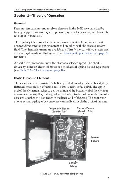
242E Temperature/Pressure <strong>Recorder</strong>-Receiver Section 2Section 2—Theory of OperationGeneralPressure, temperature, and receiver elements in the 242E are connected bytubing or pipe to measure system pressure, system temperature, and transmitteroutput (Figure 2.1).The capillary tubes from the static pressure element and receiver elementconnect directly to the piping system and are filled with the process systemfluid. Two thermal systems are available: a Class V mercury-filled system anda Class I hydrocarbon-filled system. See Instrument Specifications on page 34for details.A chart drive mechanism turns the chart at a selected speed. The chart isdriven by either an electrical motor or a mechanical, spring-wound type motor(see Table 7.2—<strong>Chart</strong> Drives on page 30).Static Pressure ElementThe sensor element consists of a helically coiled bourdon tube with a slightlyflattened cross-section of tubing coiled into a helix or flat spiral. The upperend of the element attaches to a drive arm, and the bottom end of the elementconnects to the capillary tubing, which extends into the bottom of the recordercase and attaches to a connector in the back wall of the case. The connectorallows system piping to be connected externally through the back of the case.Temperature Element(Bourdon Tube)Pressure Element(Bourdon Tube)ReceiverBellowsCapillaryTubingFigure 2.1—242E recorder components5