Barton Chart Recorder Parts Diagram - TRIONICS
Barton Chart Recorder Parts Diagram - TRIONICS
Barton Chart Recorder Parts Diagram - TRIONICS

You also want an ePaper? Increase the reach of your titles
YUMPU automatically turns print PDFs into web optimized ePapers that Google loves.
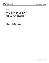
Section 4242E Temperature/Pressure <strong>Recorder</strong>-Receiver7. Disconnect the linkage for the second pen arm from the chart so that thearm moves freely. Make sure the pen follows the timeline on the chart.8. Reattach the linkage and make sure that the second pen arm is on thezero line of the chart.9. Verify calibration.Linkage AdjustmentsFinger-tightening the range arm and drive arm lock screws can leave thescrews too loose; tightening them more than a full turn can break them.To correctly tighten linkage screws, perform the following steps. Refer toFigure 4.2 - Linkage adjustments on page 18 as needed.1. Tighten the lock screw until snug.2. Hold the drive arm at the clamp block by hand or with a 1/4-inch openendwrench. If a wrench is used, place it between the torque tube shaftor bearing. (In the case of the range arm lock screw, place the wrenchbetween the pen shaft and lock screw.)3. Tighten the lock screw 1/3 of a turn to 1/2 of a turn beyond snug.4. Test for tightness by moving the free end of drive arm approximately 1/2inch in either direction. The drive arm should spring back with no yielding.Figure 4.2 - Linkage adjustments18