Barton Chart Recorder Parts Diagram - TRIONICS
Barton Chart Recorder Parts Diagram - TRIONICS
Barton Chart Recorder Parts Diagram - TRIONICS

You also want an ePaper? Increase the reach of your titles
YUMPU automatically turns print PDFs into web optimized ePapers that Google loves.
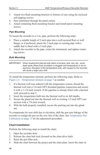
Section 3242E Temperature/Pressure <strong>Recorder</strong>-Receiver3. Attach two flush mounting brackets to bottom of case using the enclosedself-tapping screws.4. Pass instrument through the panel cutout.5. Attach remaining flush mounting bracket and install panel mountingscrews.Pipe MountingTo mount the recorder to a 2-in. pipe, perform the following steps:1. Place a suitable length of 2-inch pipe into a well-secured floor or wallflange; or if preferred, attach the 2-inch pipe to existing pipe with asaddle that is fitted with a 2-inch pipe.2. Attach the recorder to the pipe, orient the instrument, and tighten retainingscrews.Bulb MountingIMPORTANT: When locating the thermal bulb within a furnace, tank, line, etc., avoiddead spots where fluid circulation is sluggish and temperature is not responsive.Elevation of the temperature bulb, with respect to the recorder,will cause a slight zero shift.To install the temperature element, perform the following steps. Refer toFigure 2.2—Temperature element on page 7 as needed.1. If a thermal well was ordered with the temperature system, thread thethermal well into a 3/4-inch NPT threaded pipeline connection and secureit with a 1-1/8-inch wrench. If the pipeline is already fitted with a thermalwell, proceed to step 2.2. Insert the temperature bulb into the thermal well to its full depths.3. Secure the gland nut into the thermal well or existing 1/2-inch NPT connectionwith a 7/8-inch wrench.4. With the bulb properly installed, secure the packing nut into the glandnut.To compensate for zero shift due to elevation, shift the pen arm linkage of therecorder to realign the pen on the zero line of the chart. See Temperature PenCalibration on page 13 for the adjustment procedure.<strong>Chart</strong> InstallationPerform the following steps to install the chart:1. Open the recorder door.2. Release the chart hub lock (located on the chart drive hub).3. Raise the pen lifter arm.4. Slide the chart between the pen(s) and the chart plate. Insert the chart in10