Modular Sternal Cable System - Synthes
Modular Sternal Cable System - Synthes
Modular Sternal Cable System - Synthes

Create successful ePaper yourself
Turn your PDF publications into a flip-book with our unique Google optimized e-Paper software.
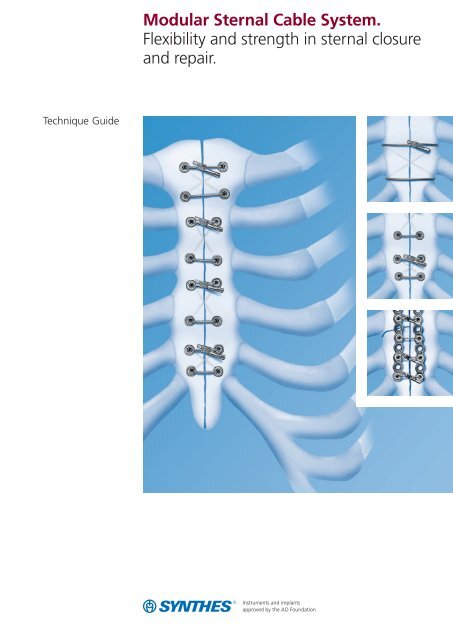
Technique Guide<strong>Modular</strong> <strong>Sternal</strong> <strong>Cable</strong> <strong>System</strong>.Flexibility and strength in sternal closureand repair.
Table of ContentsIntroductionOverview 2Indications 3Surgical TechniqueA. Use of the Tensioning, Crimping and Cutting Device 4B. Peristernal Technique Using <strong>Cable</strong> with Needle 10C. Transsternal Technique Using <strong>Cable</strong> (without Needle)and Cannulated <strong>Sternal</strong> Screws 14D. Using <strong>Cable</strong>, Cannulated Screws and Plates 22E. Emergency Removal 33Product InformationImplants 34Instruments 36WarningThis description is not sufficient for immediate application ofthe instrumentation. Instruction by a surgeon experienced inhandling this instrumentation is highly recommended.Cleaning of instrumentsFor detailed information please refer to “Reprocessing, Careand Maintenance” of <strong>Synthes</strong> instruments in the section“Medical Community” on the international <strong>Synthes</strong> websitewww.synthes.com, and to “Care and Maintenance for Tensioner/Crimper/Cutterfor <strong>Sternal</strong> <strong>Cable</strong> 1.0 mm(391.291)”, Art. No. 036.000.535.<strong>Synthes</strong> 1
OverviewThe <strong>Synthes</strong> <strong>Modular</strong> <strong>Sternal</strong> <strong>Cable</strong> <strong>System</strong> is a set ofstainless steel implants and instruments designed to facilitatesternal closure and repair.This system addresses the unique requirements of sternalclosures. Implants can be combined to meet a specific patientneed.The <strong>Sternal</strong> <strong>Cable</strong> has been designed to be used alone (withneedle), with cannulated screws (without needle) or withcannulated screws and plates (without needle).The cable’s flexibility and strength enable numerous closureoptions that provide stable fixation.The benefits of each technique, the needs of the patient,and surgeon preference should be considered when selectinga method of closure.The chosen method will dictate the<strong>Sternal</strong> <strong>Cable</strong> Sets that need to be prepared for the surgicalprocedure.This guide outlines the three surgical techniques for usingcable to close the sternum:Peristernal (around the sternum) using cable withneedleTranssternal (through the sternum) using cable(without needle) and cannulated screws<strong>Sternal</strong> Reconstruction using cable, cannulatedscrews and plates2 <strong>Synthes</strong> <strong>Modular</strong> <strong>Sternal</strong> <strong>Cable</strong> <strong>System</strong> Technique Guide
Indications– <strong>Sternal</strong> closure after sternotomy– <strong>Sternal</strong> repair and reconstruction ofsternal transverse fracturesNote: Standard sternal precautions are recommended forsix weeks after surgery, such as:– Do not lift more than 4.5 kg.– Do not pull or lift the patient by the arms.– Do not raise arms greater than 90 degrees atshoulder level.– Avoid trunk twisting.– Patient should press a pillow against his chest if he hasa strong cough.<strong>Synthes</strong> 3
A. Use of the Tensioning, Crimpingand Cutting DeviceThe Tensioner/Crimper/Cutter for <strong>Sternal</strong> <strong>Cable</strong> (391.291) isused in all techniques to secure the sternal cables. Thereforethe use of this instrument is described in the first chapterand referenced in the rest of this document.1Prepare devicePulling back on the gold collar of the Tensioner/Crimper/Cutter place the fixation sleeve into the flat side of the noseof the instrument.Release the gold collar to secure the fixation sleeve in thenose of the instrument.Note: Handles must be completely open when placing thefixation sleeve in the nose or it will not fit.4 <strong>Synthes</strong> <strong>Modular</strong> <strong>Sternal</strong> <strong>Cable</strong> <strong>System</strong> Technique Guide
2Insert cablePass the cable through the fixation sleeve in the nose of theinstrument.Note: Make sure to pass it through the flat side of the nosefirst.The gold collar may need to be pulled back slightly to passthe cable through the fixation sleeve. Make sure the fixationsleeve is facing up before pulling back on the collar, toensure that it does not fall out of the instrument.3aPosition instrumentPass the cable through the fixation sleeve until it gets contactwith the parallel end piece.Note: The gold collar can be used to rotate the nose of thetool.3bEnsure tensioning wheel is setBall detentTurn the wheel counterclockwise until the ball detent isengaged, if it is not already engaged.Engaged (correct)Not engaged (incorrect)<strong>Synthes</strong> 5
A. Use of the Tensioning, Crimpingand Cutting Device4Wrap the cable around the tensioning wheelWrap the cable clockwise (in the direction of the arrows)around the tensioning wheel on the instrument until itclicks once.Note: Do not wrap the cable more than one click aroundthe tensioning wheel to avoid a crossing of the cable duringtensioning.5Tension cableTurn the wheel clockwise (in the direction of the arrows) totension the cable appropriately. The cable should fit snug tothe bone.Important: The instrument has a clutch mechanism whichwill slip, preventing overtensioning of the cable.Note: Maximum tension is ensured when two audible clicksare heard. Avoid angling the ferrule during tensioning, asthis may cut the cable prematurely.6 <strong>Synthes</strong> <strong>Modular</strong> <strong>Sternal</strong> <strong>Cable</strong> <strong>System</strong> Technique Guide
6Verify cable positioningVerify proper position of the instrument and the parallel endpiece, as well as cable tension.Important: Ensure the parallel end fitting and ferrule arepositioned straight and along the line of the cable. The noseof the instrument should be square to the cable.7Crimp ferrule and cut cableWhen correct position and tension have been achieved,squeeze the handles together completely to crimp and cutthe cable, in one action.Note: Not squeezing the handles together completely willresult in an incomplete crimp.<strong>Synthes</strong> 7
A. Use of the Tensioning, Crimpingand Cutting Device8Release <strong>Cable</strong>Pull back on the gold collar and remove the instrument fromthe crimped fixation sleeve.9Check appropriate fixationVerify visually that the cable is tight and that the sternalhalves are correctly approximated.8 <strong>Synthes</strong> <strong>Modular</strong> <strong>Sternal</strong> <strong>Cable</strong> <strong>System</strong> Technique Guide
10Tensioning of the remaining cablesRepeat steps 1–9 to secure additional cables.<strong>Synthes</strong> 9
B. Peristernal Technique Using <strong>Cable</strong>with Needle1Suture cableSuture the cable around the two halves of the sternum, us -ing the attached cutting needle. The needle can be suturedthrough the manubrium and the intercostal spaces aroundthe sternal body and xyphoid area.Note: Always pull the cable completely through beforegoing on with further suturing.A transsternal wiring in the sternal body and xyphoid withthe cable alone is not recommended. The multifilamentstructure of the cable could lead to post-operative bleeding.2Release needleAfter weaving the cable, remove the quick-release needlefrom the end of the cable by holding the cable withone hand and pulling sharply on the needle with forceps.10 <strong>Synthes</strong> <strong>Modular</strong> <strong>Sternal</strong> <strong>Cable</strong> <strong>System</strong> Technique Guide
3Secure cablePass the end of the cable through the parallel end pieceand leave for the moment.4Place remaining cablesContinue with placement of additional cables as neededfor the desired closure.<strong>Synthes</strong> 11
B. Peristernal Technique Using <strong>Cable</strong>with Needle5Reduce sternal halvesInstruments398.902 <strong>Sternal</strong> Reduction Forceps398.985 Reduction ForcepsOptional instruments351.026 Awl 2.7 mm with Hexagonal Coupling311.006 Handle, medium, with Hexagonal CouplingTo achieve anatomical reduction of the sternum, the useof reduction forceps to approximate the sternal halves isrecommended.After the forceps are placed, tighten them to align thesternal halves into the correct anatomic position.Note: The tips of the reduction forceps can be placedintercostally. Or if necessary, the 2.7 mm awl can be usedto create pilot holes in the body of the sternum.The tips of the forceps should not be placed against thecable during reduction.12 <strong>Synthes</strong> <strong>Modular</strong> <strong>Sternal</strong> <strong>Cable</strong> <strong>System</strong> Technique Guide
6Secure <strong>Cable</strong>sTighten all cables by hand.7Tension <strong>Cable</strong>sTension, crimp and cut the cables as described in chapter A(page 4–9).<strong>Synthes</strong> 13
C. Transsternal Technique Using <strong>Cable</strong>(without Needle) and Cannulated<strong>Sternal</strong> Screws1Position screwsUsing a marking pen, identify locations for screw placementin the manubrium and sternal body.2Measure sternal edgesInstruments03.501.001 Depth Gauge for <strong>Sternal</strong> <strong>Cable</strong>Using the Depth Gauge, measure the thickness of thesternum medial to the planned screw location.Note: Bicortical screw insertion is critical for maximum effectiveness.Careful measurement and screw selection is necessary.14 <strong>Synthes</strong> <strong>Modular</strong> <strong>Sternal</strong> <strong>Cable</strong> <strong>System</strong> Technique Guide
3Select appropiate screw lengthSelect the appropriate length screw based on the depthgaugereading.4Pick up cannulated screw2 mmInstruments351.034 Screwdriver Shaft, hexagonal, adjustablewith Blade with spade point, forHexagonal Coupling311.006 Handle, medium, with Hexagonal CouplingInsert the 4.5 mm Hexagonal Adjustable Screwdriver Bladewith spade point into the Screwdriver Handle.Turn the adjustable sleeve on the screwdriver blade until thescrew length determined in step 2 is indicated. Insert thetip of the screwdriver into the recess of the screw and pressdown to secure the screw to the blade.Note: The tip of the blade should protrude approximately2 mm beyond the tip of the screw.<strong>Synthes</strong> 15
C. Transsternal Technique Using <strong>Cable</strong> (without Needle)and Cannulated <strong>Sternal</strong> Screws5Insert screwInstruments351.034 Screwdriver Shaft, hexagonal, adjustablewith Blade with spade point, forHexagonal Coupling311.006 Handle, medium, with Hexagonal CouplingInsert the screw into the sternum.When the screw is properly seated, remove the screwdriverblade by pulling straight back.Proper insertion – anterior cortexProper insertion – posterior cortex16 <strong>Synthes</strong> <strong>Modular</strong> <strong>Sternal</strong> <strong>Cable</strong> <strong>System</strong> Technique Guide
Optional instruments351.026 Awl 2.7 mm with Hexagonal Coupling311.006 Handle, medium, with Hexagonal CouplingIn dense cortical bone, use the 2.7 mm Awl with theScrewdriver Handle to pierce the outer cortex of the sternumin the desired screw location.6Insert remaining screwsInstruments351.034 Screwdriver Shaft, hexagonal, adjustablewith Blade with spade point, forHexagonal Coupling311.006 Handle, medium, with Hexagonal CouplingRepeat steps 3–5 to implant additional screws.<strong>Synthes</strong> 17
C. Transsternal Technique Using <strong>Cable</strong> (without Needle)and Cannulated <strong>Sternal</strong> Screws7Insert cablesInstruments351.027 Obturator for <strong>Sternal</strong> <strong>Cable</strong> Passer351.028 <strong>Cable</strong> Passer for <strong>Sternal</strong> <strong>Cable</strong> 1.0 mmInsert the cable anterior to posterior through the firstcannulated screw.Insert the <strong>Cable</strong> Passer with Obturator into a screw in theopposite hemisternum. Remove the Obturator. Pass the cablethrough the <strong>Cable</strong> Passer from the posterior aspect of thesternum.After pushing the end of the cable through the top of the<strong>Cable</strong> Passer, remove the <strong>Cable</strong> Passer while holding ontothe cable. Continue by passing the cable through additionalscrews.Note: The <strong>Cable</strong> Passer can also be used to pass the cablethrough the intercostal space.18 <strong>Synthes</strong> <strong>Modular</strong> <strong>Sternal</strong> <strong>Cable</strong> <strong>System</strong> Technique Guide
8Secure cablePass the end of the cable through the parallel end pieceand leave for the moment.9Place remaining cablesContinue with placement of additional cables as neededfor the desired closure.<strong>Synthes</strong> 19
C. Transsternal Technique Using <strong>Cable</strong> (without Needle)and Cannulated <strong>Sternal</strong> Screws10Reduce sternal halvesInstruments398.902 <strong>Sternal</strong> Reduction Forceps398.985 Reduction ForcepsTo achieve anatomical reduction of the sternum, the useof reduction forceps to approximate the sternal halves isrecommended.After the forceps are placed, tighten them to align thesternal halves into the correct anatomic position.20 <strong>Synthes</strong> <strong>Modular</strong> <strong>Sternal</strong> <strong>Cable</strong> <strong>System</strong> Technique Guide
11Secure <strong>Cable</strong>sTighten all cables by hand.12Tension <strong>Cable</strong>sTension, crimp and cut the cables as described in chapter A(page 4–9).<strong>Synthes</strong> 21
D. <strong>Sternal</strong> Reconstruction using <strong>Cable</strong>,Cannulated Screws and Plates4.5 mm <strong>Sternal</strong> Reconstruction Plates can be used to fixatetransverse fractures of the sternum. Plate implantationshould be performed in conjunction with muscle flap advancementto ensure adequate blood supply, and to provideadditional soft tissue coverage to the region.1Select plateSelect the plate of appropriate length.22 <strong>Synthes</strong> <strong>Modular</strong> <strong>Sternal</strong> <strong>Cable</strong> <strong>System</strong> Technique Guide
2Contour bending templateInstrument329.400 Bending TemplateUsing the Bending Template, determine the contour of thehemisternum3Contour plateInstrument329.142 Bending Pliers with NoseWith the Bending Template as a guide, use the CombinationBending Pliers to contour the plate, in the following sequence:In-plane bendPlace the plate into the jaws of the bender. Squeeze thehandles together to bend the plate.<strong>Synthes</strong> 23
D. <strong>Sternal</strong> Reconstruction using <strong>Cable</strong>, Cannulated Screwsand PlatesOut-of-plane bendPlace the plate into the jaws of the bender. Squeeze thehandles together to bend the plate.Or:Place the plate into the “duckbill” end of the bender.Squeeze the handles together to bend the plate.24 <strong>Synthes</strong> <strong>Modular</strong> <strong>Sternal</strong> <strong>Cable</strong> <strong>System</strong> Technique Guide
4Place platePlace the plate on the sternum to verify contour accuracy.Profile of plate on the sternum5Measure sternal edgesInstruments03.501.001 Depth Gauge for <strong>Sternal</strong> <strong>Cable</strong>Using the Depth Gauge, measure the thickness of thesternum medial to the planned screw location.Note: Bicortical screw insertion is critical for maximumeffectiveness. Careful measurement and screw selectionis necessary.<strong>Synthes</strong> 25
D. <strong>Sternal</strong> Reconstruction using <strong>Cable</strong>, Cannulated Screwsand Plates6Select appropiate screwSelect the appropriate length screw based on the depthgauge reading, adding 3 mm to allow for plate thickness.7Pick up cannulated screw2 mmInstruments351.034 Screwdriver Shaft, hexagonal, adjustablewith Blade with spade point, forHexagonal Coupling311.006 Handle, medium, with Hexagonal CouplingInsert the 4.5 mm Hexagonal Adjustable Screwdriver Bladewith spade point into the Screwdriver Handle. Turn theadjustable sleeve on the screwdriver blade until the screwlength determined in step 6 is indicated. Insert the tip ofthe screwdriver into the recess of the screw and press downto secure the screw to the blade.Note: The tip of the blade should protrude approximately2 mm beyond the tip of the screw.26 <strong>Synthes</strong> <strong>Modular</strong> <strong>Sternal</strong> <strong>Cable</strong> <strong>System</strong> Technique Guide
8Attach plate to the sternumInstruments351.034 Screwdriver Shaft, hexagonal, adjustablewith Blade with spade point, forHexagonal Coupling311.006 Handle, medium, with Hexagonal CouplingUsing 4.5 mm <strong>Sternal</strong> Cannulated Screws, attach the plateto the sternum. Placing screws every two to three plate holesis recommended.Note: If spanning a transverse fracture, placing screws adjacentto (but not in) the fracture is also recommended.Optional instruments351.026 Awl 2.7 mm with Hexagonal Coupling311.006 Handle, medium, with Hexagonal CouplingIn dense cortical bone, use the 2.7 mm Awl with the ScrewdriverHandle to pierce the outer cortex of the sternum in thedesired screw location.<strong>Synthes</strong> 27
D. <strong>Sternal</strong> Reconstruction using <strong>Cable</strong>, Cannulated Screwsand Plates9Attach remaining platesRepeat this process with the other hemisternum as needed.10Secure cableInstruments351.027 Obturator for <strong>Sternal</strong> <strong>Cable</strong> Passer351.028 <strong>Cable</strong> Passer for <strong>Sternal</strong> <strong>Cable</strong> 1.0 mmInsert the cable anterior to posterior through the firstcannulated screw.Insert the <strong>Cable</strong> Passer with Obturator into a screw in theopposite hemisternum. Remove the Obturator. Pass the cablethrough the <strong>Cable</strong> Passer from the posterior aspect of thesternum.After pushing the end of the cable through the top of the<strong>Cable</strong> Passer, remove the <strong>Cable</strong> Passer while holding ontothe cable. Continue by passing the cable through additionalscrews.28 <strong>Synthes</strong> <strong>Modular</strong> <strong>Sternal</strong> <strong>Cable</strong> <strong>System</strong> Technique Guide
11Secure <strong>Cable</strong>sPass the end of the cable through the parallel end fitting.12Alternative: Secure cables through transverse holesThe cable may be used without the parallel end fittingand terminated with a ferrule after passing it through a sidehole in the plate.To use this technique, first remove the parallel end fittingfrom the cable. Pass the cable through the first cannulatedscrew from anterior to posterior. The finished end of thecable will sit flush in the head of the screw, as shown.<strong>Synthes</strong> 29
D. <strong>Sternal</strong> Reconstruction using <strong>Cable</strong>, Cannulated Screwsand PlatesWhen finished weaving the cable, pass it through a side holein the plate.13Place remaining cablesContinue with placement of additional cables as needed forthe desired closure.Note: It is recommended that a minimum of ten total loopsbe used for closure with plates and screws, either usingten single loops, five figure of eight loops (two loops each),or a combination of each totaling ten loops.30 <strong>Synthes</strong> <strong>Modular</strong> <strong>Sternal</strong> <strong>Cable</strong> <strong>System</strong> Technique Guide
14Reduce sternal halvesInstruments398.902 <strong>Sternal</strong> Reduction Forceps398.985 Reduction ForcepsTo achieve anatomical reduction of the sternum, the useof reduction forceps to approximate the sternal halves isrecommended.After the forceps are placed, tighten them to align thesternal halves into the correct anatomic position.Note: The tips of the forceps should not be placed againstthe plates, screws or cables during reduction.<strong>Synthes</strong> 31
D. <strong>Sternal</strong> Reconstruction using <strong>Cable</strong>, Cannulated Screwsand Plates15Secure <strong>Cable</strong>sTighten all cables by hand.16Tension <strong>Cable</strong>sTension, crimp and cut the cables as described in chapter A(page 4–9).32 <strong>Synthes</strong> <strong>Modular</strong> <strong>Sternal</strong> <strong>Cable</strong> <strong>System</strong> Technique Guide
E. Emergency Removal1Cut cableInstruments391.905 <strong>Cable</strong> Cutter standardIn case of emergency, the cable can be cut using standardwire cutters; however, using the <strong>Cable</strong> Cutter is recommended.Note: If cannulated screws have been used, they may be leftin the sternum and used again as a channel for cable passage.<strong>Synthes</strong> 33
Implants291.911.01S<strong>Sternal</strong> <strong>Cable</strong> 1.0 mm, with FixationSleeve and Parallel End Piece, StainlessSteel, sterile291.916.01S<strong>Sternal</strong> <strong>Cable</strong> 1.0 mm, with Needle,Fixation Sleeve, and Parallel Endpiece,Stainless Steel, sterile291.906.05 Fixation Sleeve for <strong>Sternal</strong> <strong>Cable</strong>291.907.05 Parallel End Piece for <strong>Sternal</strong> <strong>Cable</strong>34 <strong>Synthes</strong> <strong>Modular</strong> <strong>Sternal</strong> <strong>Cable</strong> <strong>System</strong> Technique Guide
Cannulated <strong>Sternal</strong> Screw 4.5 mmLengths: 8 mm–24 mm (1 mm increments)Length Non-sterile sterile8 mm 213.508 213.508S9 mm 213.509 213.509S10 mm 213.510 213.510S11 mm 213.511 213.511S12 mm 213.512 213.512S13 mm 213.513 213.513S14 mm 213.514 213.514S15 mm 213.515 213.515S16 mm 213.516 213.516S17 mm 213.517 213.517S18 mm 213.518 213.518S19 mm 213.519 213.519S20 mm 213.520 213.520S21 mm 213.521 213.521S22 mm 213.522 213.522S23 mm 213.523 213.523S24 mm 213.524 213.524S25 mm 213.525 213.525S26 mm 213.526 213.526S<strong>Sternal</strong> Reconstruction Plate 4.5, Stainless SteelLengths: 80 mm–192 mm (16 mm increments)Holes Length Non-sterile sterile10 80 mm 260.060 260.060S12 96 mm 260.062 260.062S14 112 mm 260.064 260.064S16 128 mm 260.066 260.066S18 144 mm 260.068 260.068S20 160 mm 260.070 260.070S22 176 mm 260.072 260.072S24 192 mm 260.074 260.074S<strong>Synthes</strong> 35
Instruments311.006 Handle, medium, with Hexagonal Coupling03.501.001 Depth Gauge for <strong>Sternal</strong> <strong>Cable</strong>329.400 Bending Template329.142 Bending Pliers with Nose351.026 Awl 2.7 mm with Hexagonal Coupling36 <strong>Synthes</strong> <strong>Modular</strong> <strong>Sternal</strong> <strong>Cable</strong> <strong>System</strong> Technique Guide
351.027 Obturator for <strong>Sternal</strong> <strong>Cable</strong> Passer351.028 <strong>Cable</strong> Passer for <strong>Sternal</strong> <strong>Cable</strong> 1.0 mm351.034 Screwdriver Shaft, hexagonal, adjustablewith Blade with spade point, forHexagonal Coupling351.035 Spare Blade for Screwdriver Shaft,hexagonal, adjustable, for No. 351.034<strong>Synthes</strong> 37
Instruments391.291 Tensioner/Crimper/Cutter for <strong>Sternal</strong> <strong>Cable</strong>391.905 <strong>Cable</strong> Cutter standard38 <strong>Synthes</strong> <strong>Modular</strong> <strong>Sternal</strong> <strong>Cable</strong> <strong>System</strong> Technique Guide
398.902 <strong>Sternal</strong> Reduction Forceps398.985 Reduction Forceps<strong>Synthes</strong> 39
Presented by:0123036.000.190 SE_058371 AC 61080005 © 04/2008 <strong>Synthes</strong>, Inc. or its affiliates All rights reserved <strong>Synthes</strong> is a trademark of <strong>Synthes</strong>, Inc. or its affiliates