Capacitive Proximity Sensor E2J - OMRON Russia ...
Capacitive Proximity Sensor E2J - OMRON Russia ...
Capacitive Proximity Sensor E2J - OMRON Russia ...
- No tags were found...

Create successful ePaper yourself
Turn your PDF publications into a flip-book with our unique Google optimized e-Paper software.
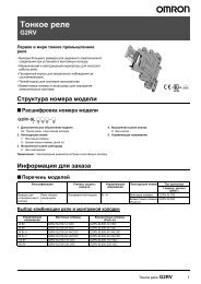
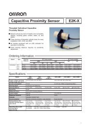
<strong>Capacitive</strong> <strong>Proximity</strong> <strong>Sensor</strong><strong>E2J</strong>Compact and Ideal for Robot Hands andVarious Built-in Applications for LCD,Wafer, and PDP (Plasma Display Panel)DetectionFlat head is only 5.5-mm thick.Robot Cable ensures improved flexibility.Sensing indicator of the <strong>Sensor</strong> Head is clearlyvisible in the dark.Easy-to-use connector.Application ExamplesDetection of Printed Circuit Glass Boards on ConveyorsDetection of Printed Circuit Glass Boards in Cartridges<strong>E2J</strong><strong>E2J</strong>Ordering Information<strong>Sensor</strong>sFlatType Sensing distance ModelUnshieldedMin.sensingdistanceAdjustablerange4to10mmMax. sensing distance<strong>E2J</strong>-W10MASensing range0to10mmMin.sensingdistanceAdjustable range8to20mmMax. sensing distance<strong>E2J</strong>-W20MASensing range0to20mm1
<strong>E2J</strong><strong>E2J</strong>Amplifier UnitOutput configurationDC 3-wireNPN open collector<strong>E2J</strong>-JC4AModelAccessories (Sold Separately)Dust CoversModel Material ApplicableXS3Z-13Red polyvinylchloride<strong>E2J</strong>-JC4AAmplifier UnitXS3Z-15<strong>E2J</strong>-WjMA<strong>Sensor</strong> HeadNote: Refer to page 6.SpecificationsRatings/Characteristics<strong>Sensor</strong>sM8-screw-mounting Vibration-proof RobotCablesNumber of Cable length (L) Modelconductors4 1 XS3W-M421-401-R2 XS3W-M421-402-RNote: Refer to page 6.Item <strong>E2J</strong>-W10MA <strong>E2J</strong>-W20MASensing distance adjustable range 4to10mm 8to20mmSensing range 0to10mm 0to20mmStandard sensing objectSensing objectDifferential travelResponse frequencyAmbient temperature50 x 50 mm grounded metal (t = 1 mm)Conductors and inductive objects15% max. of sensing distance70 kHz max.Operating: --10!C to55!CAmbient humidity Operating: 35% to 95%Enclosure ratingIEC IP66Vibration resistanceMalfunction: 10 to 500 Hz, 2.0-mm double amplitude or 150 m/s 2 (approx. 15G) for 2 hrs eachin X, Y, and Z directionsShock resistanceMalfunction: 500 m/s 2 (approx. 50G) for 3 times each in X, Y, and Z directionsWeight Approx. 30 g Approx. 40 gCase materialABS resinAmplifier UnitItemSupply voltageCurrent consumptionControl outputOutput residual voltageCircuit protectionAmbient temperature24 VDC"10%, ripple (p-p): 10% max.30 mA max.100 mA max., NPN open collector1Vmax.<strong>E2J</strong>-JC4AReverse connection, load short-circuit, and surge absorptionOperating: --10!C to55!CAmbient humidity Operating: 35% to 85%Temperature influence"25% max. of sensing distance at 23!C in temperature range of 0!C to40!C(<strong>Sensor</strong> Head and Amplifier Unit)Voltage influence "1% max. of sensing distance in rated voltage range of "20%Insulation resistanceDielectric strengthVibration resistanceShock resistanceEnclosure ratingWeightCase material50 M# (at 500 VDC) between current carry parts and case1,000 VAC (50/60 Hz) for 1 min between current carry parts and caseMalfunction: 10 to 150 Hz, 1.5-mm double amplitude or 150 m/s 2 (approx. 15G) for 2 hrs eachin X, Y, and Z directionsMalfunction: 300 m/s 2 (approx. 30G) for 3 times each in X, Y, and Z directionsIEC IP50Approx. 60 gABS2
<strong>E2J</strong><strong>E2J</strong>OperationOutput CircuitAmplifier Unit<strong>Sensor</strong> HeadBrown24 VDCMaincircuitMaincircuit100 mA max.BlackOutputLoadBlue0VOperating ChartsPower indicatorONOFFMode selectorSensing objectOutput transistor<strong>Sensor</strong> Headsensing indicatorAmplifier Unitoperation indicatorYesNoONOFFONOFFThe output transistor is ON when thesensing object is detected.The output transistor is ON when thesensing object is not detected.Engineering Data (Typical)Sensing Distance vs. Sensing Object (Iron)<strong>E2J</strong>-W10MA<strong>E2J</strong>-W20MASensing distance X (mm)GroundedNon-grounded (Sensitivity adjuster: Max.)GroundedSensing distance X (mm)Grounded(Sensitivity adjuster: Max.)Non-groundedGrounded(Sensitivity adjuster: Min.)Non-grounded(Sensitivity adjuster: Min.)Non-groundedSide length of sensing object d (mm)Side length of sensing object d (mm)3
<strong>E2J</strong><strong>E2J</strong>Influence of Ambient Temperature<strong>E2J</strong>-W10MA<strong>E2J</strong>-W20MAVariationrate(%)Variationrate(%)Temperature (!C)Temperature (!C)Sensing Distance of Sensing Objects<strong>E2J</strong>-W10MA<strong>E2J</strong>-W20MAMaximum sensing distance (mm)Maximum sensing distance (mm)Groundediron50 x 50 mmt=1 mmNon-grounded Acryl Glass Siliconironwafer50 x 50 mmt=1 mm50 x 50 mmt=10 mm150 x 180 mmt=1.2 mmGroundedironNon-grounded Acryl Glass Siliconironwafer2 inches 50 x 50 mm 50 x 50 mm 50 x 50 mm 150 x 180 mm 2 inchest=1 mm t=1 mm t=10 mm t=1.2 mmSensing Ranges<strong>E2J</strong>-W10MA<strong>E2J</strong>-W20MAVertical direction X (mm)SensingobjectGrounded iron (50x50x1 mm)GlassVertical direction X (mm)SensingobjectGrounded iron (50x50x1 mm)GlassLED side of<strong>Sensor</strong>HeadNon-LED sideof <strong>Sensor</strong>HeadLED side of<strong>Sensor</strong>HeadNon-LED sideof <strong>Sensor</strong>HeadHorizontal direction Y (mm)Horizontal direction Y (mm)4
<strong>E2J</strong><strong>E2J</strong>Nomenclature<strong>E2J</strong>-JC4APower indicator (green)Operation indicator (orange)Sensitivity indicatorSensitivity adjusterOperation mode selectorDimensions<strong>Sensor</strong>s<strong>E2J</strong>-W10MASensing side9dia.Two, 3.2 dia.Sensing indicator (red)4-dia. (40/0.08 dia.) robot cablewith four conductors; standardlength: 1 mMounting HolesTwo, M3<strong>E2J</strong>-W20MASensing side9dia.Two, 3.2 dia.Sensing indicator (red)4-dia. (40/0.08 dia.) robot cablewith four conductors; standardlength: 1 mMounting HolesTwo, M35
<strong>E2J</strong><strong>E2J</strong>Amplifier Unit<strong>E2J</strong>-JC4A M8 connector Operation indicatorPower indicator4-dia. (18 x 0.12 dia.)vinyl-insulated round cordwith three conductors;standard length: 2 mTwo, Mounting Bracket3.2 dia.Two, mounting holesFour, 1.7 radiusDust CoversXS3Z-13XS3Z-15XS3Z-13XS3Z-15Note: Although the XS3Z Dust Covers protect the <strong>E2J</strong> from dust, they do not satisfy IP67. When attaching the Dust Cover, be sure to fullyinsert the connector into the Dust Cover.M8-screw-mounting Vibration-proof Robot CableSocket4dia.Plug9dia.10 dia.6
<strong>E2J</strong><strong>E2J</strong>PrecautionsObserve the following precautions to ensure safety.1. Do not use the <strong>Sensor</strong> in an environment where it will be exposed to inflammable or explosive gases.2. Do not attempt to disassemble, repair, or modify the <strong>Sensor</strong>.3. Be careful not to connect the power source with the polarities in reverse.4. Do not short-circuit the loads.5. Do not use the <strong>Sensor</strong> at voltages exceeding the rated voltage.Correct UseHandling$ Do not use the <strong>Sensor</strong> outdoors.$ Do not wire the <strong>Sensor</strong> alongside a high-tension or power line.$ Do not use portable telephones or transceivers near the <strong>Sensor</strong>.Be sure to ground the Mounting Brackets.$ Do not use the <strong>Sensor</strong> in an environment where it will be exposedto chemicals, particularly chemical solutions or oxidizing acids.MountingBe sure that the tightening torque does not exceed the followingvalue.Mutual InterferenceWhen mounting more than two <strong>Sensor</strong>s face to face or side by side,ensure that the minimum distances given in the following table aremaintained.Distance <strong>E2J</strong>-W10MA <strong>E2J</strong>-W20MAE 20 mm 70 mmF 30 mm 50 mmALocationTorque0.54N S m {5.5 kgf S cm} max.Effects of Surrounding MetalBefore mounting the <strong>Sensor</strong>, be sure that the <strong>Sensor</strong> will be separatedfrom surrounding objects as shown in the following illustration.Sensing side<strong>Sensor</strong>Sensing side<strong>Sensor</strong>Metal objectBe sure toground themetal object.Metal objectBe sure toground themetal object.Dimension <strong>E2J</strong>-W10MA <strong>E2J</strong>-W20MAB 10 mm 20 mmC 20 mm 40 mmEffects of Static ElectricityBe sure to discharge static electricity before detecting objects thatare greatly affected by static electricity.7
<strong>E2J</strong><strong>E2J</strong>Adjustment Procedure1Step Sensing Sensitivity adjuster AdjustmentSensing object--- Obtain the sensing distance X from theset distance S divided by 0.75.Determine S so that X will be less thanthe maximum sensing distance.23Sensing objectSensing objectLocate the <strong>Sensor</strong> so that the distancebetween the <strong>Sensor</strong> and sensing objectis X. Turn the sensitivity adjusterclockwise until the red sensing indicatorof the <strong>Sensor</strong> Head is lit.--- Return the <strong>Sensor</strong> to the previousposition so that the distance betweenthe <strong>Sensor</strong> and sensing object is S.Note: After completing sensitivity adjustment, mount the provided cover on the Amplifier Unit to prevent mis-operation.$ The maximum sensing distance will drop depending on the dimensions and material of the sensing object. Refer to Engineering Data.$ Since a different adjustment procedure must be taken if the ambient temperature is outside the specified temperature range (0!Cto40!C),contact your <strong>OMRON</strong> sales representative.Cord$ Be sure that the bending radius of the cord is more than 5 mm.$ Use the XS3W-M421-40j-R with connectors (M8-screwmountingtype) as the extension cord. The maximum cord lengthis 3 m (extension section: 2 m).Mounting and Dismounting the Amplifier UnitMounting1. Mount the front part of the amplifier to the mounting bracketprovided with the amplifier or a DIN track.2. Press the rear part of the amplifier onto the mounting bracketor DIN track.Rear partFront partFixture railDIN track or Mounting BracketDismounting3. Pull the fixture rail with a flat-blade screwdriver so that theAmplifier Unit can be dismounted with ease.ALL DIMENSIONS SHOWN ARE IN MILLIMETERS.To convert millimeters into inches, multiply by 0.03937. To convert grams into ounces, multiply by 0.03527.Cat. No.D062-E1-1<strong>OMRON</strong> CorporationSystems Components Division H.Q.28th Fl., Crystal Tower Bldg.1-2-27, Shiromi, Chuo-ku,Osaka 540 JapanPhone: 06-949-6012 Fax: 06-949-6021In the interest of product improvement, specifications are subject to change without notice.Printed in Japan0697-2M (0697) a8