UniOP User's Manual - Esco Drives & Automation
UniOP User's Manual - Esco Drives & Automation
UniOP User's Manual - Esco Drives & Automation

Create successful ePaper yourself
Turn your PDF publications into a flip-book with our unique Google optimized e-Paper software.
Tech-note<strong>UniOP</strong> <strong>User's</strong><strong>Manual</strong>Updated for Designer 6.06Sitek S.p.A.Tn179-05Ver. 1.00
Tech-noteCopyright © 2007 Sitek S.p.A. – Verona, ItalySubject to change without noticeThe information contained in this document is provided for informational purposes only. Whileefforts were made to verify the accuracy of the information contained in this documentation, it isprovided “as is” without warranty of any kind.Third-party brands and names are the property of their respective owners.www.exor-rd.comTn179-05.doc - 12.01.2007<strong>UniOP</strong> <strong>User's</strong> <strong>Manual</strong> 2
Tech-noteTable Of Contents1 Welcome ...........................................................................................................................72 Quick Start ........................................................................................................................22.1 Quick Start Tutorial Introduction ..........................................................................22.1.1 Development Environment Setup ........................................................................22.2 Quick Start Tutorial ..............................................................................................33 Installation .........................................................................................................................93.1 Overview ..............................................................................................................93.2 Assumptions.........................................................................................................93.3 Conventions .........................................................................................................93.4 System Requirements........................................................................................103.4.1 Free hard disk space..........................................................................................103.4.2 RAM Memory .....................................................................................................103.4.3 Supported Operating Systems:..........................................................................103.5 Software Installation...........................................................................................103.6 Connecting the Panel to the PC.........................................................................123.7 How to Report a Bug..........................................................................................133.8 Technical Support ..............................................................................................133.9 Contact Information............................................................................................133.10 Designer Software License ................................................................................143.10.1 SOFTWARE LICENSE ......................................................................................143.10.2 Grant of License.................................................................................................143.10.3 Limitations ..........................................................................................................143.10.4 COPYRIGHT......................................................................................................153.10.5 INTELLECTUAL PROPERTY............................................................................153.10.6 DISCLAIMER (Limited Warranty) ......................................................................154 Reference........................................................................................................................154.1 File Menu ...........................................................................................................154.1.1 File Menu ...........................................................................................................154.1.2 New ....................................................................................................................164.1.3 Open ..................................................................................................................174.1.4 Close ..................................................................................................................174.1.5 Save ...................................................................................................................174.1.6 Save As..............................................................................................................174.1.7 Print....................................................................................................................184.1.8 Print Preview ......................................................................................................184.1.9 Designer Print Setup..........................................................................................184.1.10 Export to tag database.......................................................................................214.1.11 Export Strings.....................................................................................................214.1.12 Import Strings.....................................................................................................234.1.13 Recent Files .......................................................................................................244.1.14 Exit .....................................................................................................................244.2 Edit Menu ...........................................................................................................244.2.1 Edit Menu ...........................................................................................................244.2.2 Undo...................................................................................................................244.2.3 Redo...................................................................................................................244.2.4 Cut......................................................................................................................244.2.5 Copy...................................................................................................................254.2.6 Paste ..................................................................................................................254.2.7 Select All ............................................................................................................254.2.8 Align ...................................................................................................................254.2.16 Make Same Size................................................................................................264.2.21 Fonts ..................................................................................................................274.3 View Menu .........................................................................................................304.3.1 View Menu .........................................................................................................30Tn179-05.doc - 12.01.2007<strong>UniOP</strong> <strong>User's</strong> <strong>Manual</strong>iii
Tech-note4.3.2 Zoom In ..............................................................................................................304.3.3 Zoom Out ...........................................................................................................314.3.4 Status Bar ..........................................................................................................314.3.5 Toolbars .............................................................................................................324.3.8 Workspace .........................................................................................................344.3.9 Full Screen .........................................................................................................344.3.10 Graphics Library.................................................................................................354.3.15 Layers ................................................................................................................384.4 Insert Menu ........................................................................................................414.4.1 Insert Menu ........................................................................................................414.4.2 Text ....................................................................................................................424.4.3 Bitmap ................................................................................................................424.4.4 Data Fields .........................................................................................................444.4.85 Touch Cells ......................................................................................................1044.4.162 Shapes .............................................................................................................1464.4.167 Trend Window ..................................................................................................1474.4.228 Meter Instrument..............................................................................................1574.4.286 Trend Time Field..............................................................................................1684.4.296 Recipe Menu ....................................................................................................1724.4.305 Special Characters...........................................................................................1754.4.306 Import Bitmap Graphics ...................................................................................1754.5 Page Menu.......................................................................................................1824.5.1 Page Menu.......................................................................................................1824.5.2 Insert Page.......................................................................................................1824.5.3 Add Page .........................................................................................................1824.5.4 Delete Page .....................................................................................................1824.5.5 Go to Page .......................................................................................................1834.5.6 Previous Page..................................................................................................1834.5.7 Next Page ........................................................................................................1834.5.8 Page Options ...................................................................................................1834.5.14 Recipe Configuration........................................................................................1844.5.26 Special Pages and Page Modes......................................................................1874.6 Project Menu ....................................................................................................1904.6.1 Project Menu ....................................................................................................1904.6.2 Configure Controller.........................................................................................1904.6.19 Panel Setup......................................................................................................1944.6.78 Network Setup..................................................................................................2084.6.112 Panel Controller Interface ................................................................................2184.6.140 Report on Panel Printer ...................................................................................2264.6.201 Passwords........................................................................................................2404.6.215 Languages .......................................................................................................2464.6.224 Next Language.................................................................................................2484.6.225 Configure Tag Dictionaries ..............................................................................2484.6.231 Tag Validation ..................................................................................................2504.6.232 Trend Buffers ...................................................................................................2504.6.266 Memory Use.....................................................................................................2574.6.267 Time Scheduled Triggers.................................................................................2574.7 Transfers Menu................................................................................................2614.7.1 Transfers Menu................................................................................................2614.7.2 Download .........................................................................................................2624.7.3 Upload..............................................................................................................2634.7.4 Download to SSFDC........................................................................................2634.7.10 Options.............................................................................................................2664.7.44 Get Panel Resources.......................................................................................2744.7.45 Check Firmware Versions................................................................................2754.7.46 Switch to Operation mode................................................................................2764.7.47 Switch to Configuration mode ..........................................................................2764.7.48 Remote Passthrough .......................................................................................2764.7.53 Dial ...................................................................................................................2774.7.54 Hang Up ...........................................................................................................278Tn179-05.doc - 12.01.2007<strong>UniOP</strong> <strong>User's</strong> <strong>Manual</strong>iv
Tech-note4.8 Tools Menu ......................................................................................................2784.8.1 Tools Menu ......................................................................................................2784.8.2 Tag Editor.........................................................................................................2784.8.66 Font Editor........................................................................................................2974.8.94 Keypad Designer..............................................................................................3064.8.139 Customize ........................................................................................................3234.8.165 Options.............................................................................................................3334.8.176 Advanced .........................................................................................................3364.8.185 Replace Images ...............................................................................................3394.9 Window Menu ..................................................................................................3404.9.1 Window Menu ..................................................................................................3404.9.2 New Window ....................................................................................................3414.9.3 Cascade ...........................................................................................................3414.9.4 Tile Horizontally................................................................................................3414.9.5 Tile Vertically....................................................................................................3414.10 Application Menu..............................................................................................3414.10.1 Application Menu..............................................................................................3414.10.2 Restore.............................................................................................................3414.10.3 Move ................................................................................................................3424.10.4 Size ..................................................................................................................3424.10.5 Minimize ...........................................................................................................3424.10.6 Maximize ..........................................................................................................3424.10.7 Close ................................................................................................................3425 Workspace ....................................................................................................................3425.1 Workspace .......................................................................................................3425.2 Graphics...........................................................................................................3445.3 Objects .............................................................................................................3455.4 Project ..............................................................................................................3465.4.1 Project ..............................................................................................................3465.4.2 Data Transfer ...................................................................................................3466 Basics............................................................................................................................3486.1 Basics...............................................................................................................3486.2 Designer Screen ..............................................................................................3486.2.1 Designer Screen ..............................................................................................3486.2.2 Menu Bar..........................................................................................................3496.2.3 Toolbars ...........................................................................................................3506.2.4 Workspace .......................................................................................................3526.2.5 Project Screen..................................................................................................3526.2.6 Status Bar ........................................................................................................3536.2.7 Right-Click Menus............................................................................................3546.2.8 Tooltips.............................................................................................................3556.2.9 Getting Help .....................................................................................................3556.3 Designer Setup ................................................................................................3556.3.1 Designer Setup ................................................................................................3556.3.2 Transfer Settings..............................................................................................3556.3.3 Controller Selection and Setup ........................................................................3566.3.7 Panel Selection and Setup...............................................................................3576.4 Creating a Project ............................................................................................3596.4.1 Creating a Project ............................................................................................3596.4.2 Creating a New File..........................................................................................3596.4.3 Selecting a Font ...............................................................................................3606.4.4 Inserting Page Objects.....................................................................................3606.4.5 Saving a Project File ........................................................................................3606.4.6 Memory Used by the Project File.....................................................................3606.5 Printing .............................................................................................................3616.6 Project Upload and Download .........................................................................3616.7 Simple Data Fields...........................................................................................3616.8 Simple Touch Cells ..........................................................................................3627 Advanced ......................................................................................................................363Tn179-05.doc - 12.01.2007<strong>UniOP</strong> <strong>User's</strong> <strong>Manual</strong>v
Tech-note7.1 Automatic Firmware Upgrade Procedure ........................................................3637.1.1 Automatic Firmware Upgrade Procedure ........................................................3637.1.2 Procedure to Upgrade the Internal Flash Memory...........................................3647.1.3 Check Firmware Versions................................................................................3647.1.4 Designer Firmware Files Directory...................................................................3667.1.5 FW Rescue Mode ............................................................................................3667.2 Double Protocol................................................................................................3677.2.1 Double Protocol................................................................................................3677.2.2 Enabling Multiple-Protocol Configuration.........................................................3687.2.3 Controllers Setup .............................................................................................3707.2.4 Placing Fields on a Page .................................................................................3707.2.5 Downloading Uploading and Getting Panel Resources...................................3727.2.6 Configuring UniNET Networks .........................................................................3727.3 Interlock Mailbox ..............................................................................................3737.3.1 Interlock Mailbox ..............................................................................................3737.3.2 Enabling the Internet Mailbox ..........................................................................3747.3.6 Structure of the Mailbox ...................................................................................3757.3.11 Interlock Mailbox Commands...........................................................................3777.3.35 Mailbox Programming ......................................................................................3877.4 Networks ..........................................................................................................3897.4.1 UniNET Networks.............................................................................................3897.4.2 General Characteristics ...................................................................................3907.4.7 Network Configurations....................................................................................3947.4.12 Network Types .................................................................................................3977.4.20 Connecting Panels to the Network...................................................................4007.4.34 Network Setup..................................................................................................4067.4.39 Advanced Network Programming ....................................................................4077.4.47 Network Examples ...........................................................................................4127.5 Panel Fonts ......................................................................................................4167.5.1 Panel Fonts ......................................................................................................4167.5.2 Installing New Panel Fonts ..............................................................................4177.5.8 Downloading Panel Fonts ................................................................................4187.5.9 Compressing Panel Fonts................................................................................4197.6 Printing .............................................................................................................4207.6.1 Printing .............................................................................................................4207.6.2 Printer Setup ....................................................................................................4207.6.3 Reports.............................................................................................................4207.6.9 Printer Setup Example .....................................................................................4227.7 RDA..................................................................................................................4237.7.1 RDA..................................................................................................................4237.7.2 Keyboard Update Area ....................................................................................4257.7.3 Panel Status Area ............................................................................................4267.7.23 Controller Update Area ....................................................................................4297.8 Recipes ............................................................................................................4337.8.1 Recipes ............................................................................................................4337.8.2 Working with Recipes.......................................................................................4347.8.3 Inserting Recipe Data Fields............................................................................4347.8.4 Configuring Recipe Parameter Sets ................................................................4347.8.5 Recipes and Control Variables ........................................................................4357.8.14 Recipes and the Keyboard Macro Editor .........................................................4417.8.15 Recipe Menu ....................................................................................................4417.8.25 Recipes and the Interlock Mailbox...................................................................4457.8.26 Multipage Recipe Support................................................................................4457.8.31 Recipes and Events Backup in Flash ..............................................................4477.8.34 Recipe Example...............................................................................................4497.9 Tags .................................................................................................................4547.9.1 Tags .................................................................................................................4547.9.2 Tag Dictionaries ...............................................................................................4557.9.6 Tag Editor.........................................................................................................4567.9.11 Using Tags in Designer....................................................................................458Tn179-05.doc - 12.01.2007<strong>UniOP</strong> <strong>User's</strong> <strong>Manual</strong>vi
Tech-note7.9.12 Tag Validation ..................................................................................................4587.9.15 Tag Example ....................................................................................................4597.10 Trends ..............................................................................................................4617.10.1 Trends ..............................................................................................................4617.10.2 Trend Buffer .....................................................................................................4627.10.9 Trend Window ..................................................................................................4647.10.17 Internal Panel Control Variables ......................................................................4677.10.18 Trend Macros ...................................................................................................4677.10.19 Trend Printing...................................................................................................4677.10.20 Mailbox.............................................................................................................4677.10.21 Trend Limitations..............................................................................................4687.11 Working with Graphics .....................................................................................4687.11.1 Working with Graphics .....................................................................................4687.11.2 Simple Shapes.................................................................................................4697.11.3 Graphics Libraries............................................................................................4707.11.4 Objects Libraries ..............................................................................................4727.11.5 Color Boxes......................................................................................................4747.12 Ethernet Connectivity.......................................................................................4757.12.1 Assigning IP Address to Panel.........................................................................4757.12.10 Selecting Ethernet Communication in Designer ..............................................4797.12.11 Pick Panel: The Ethernet Control Panel ..........................................................4807.12.15 Clock Synchronization with the SNTP Protocol ...............................................4827.12.16 Using UniDataExchanger.................................................................................4837.12.23 Basic Ethernet Diagnostic with Ping ................................................................4867.13 Getting Started with B Series Panels...............................................................4867.13.1 The New Hardware Platform for <strong>UniOP</strong> Panels...............................................4867.13.3 Support for 64K Colors ....................................................................................4877.13.4 The FW60 Memory Architecture ......................................................................4877.13.5 The Internal Memory........................................................................................4887.13.7 Video Input Option ...........................................................................................4907.13.13 Backlight Dimming ...........................................................................................4967.13.14 Compatibility Issues .........................................................................................4978 Index..............................................................................................................................4981 WelcomeDeveloping applications for a <strong>UniOP</strong> panel is quick and painless when using Designersoftware. The common functionality found among many Windows applications can also befound in Designer. This familiar interface style helps new users to quickly learn the Designersoftware.A completed project file of format *.dpr contains all the information needed to display yourpage images and controller data values in the formats you selected while creating yourproject file. The panel hardware will handle all of the underlying communications necessaryto transfer data to and from the controller, leaving you free to concentrate on the appearanceand functionality of your data and display pages.Note: Depending on the particular configuration of your project, one or more additional filesmay be necessary to convey all the necessary information about a project. These additionalfiles may contain information about Keypad Designer, UniSSFDC, Font Editor, Nice FontEditor, etc. The project file itself may, in certain cases, not be sufficient to contain all theinformation necessary to reproduce the application.Designer makes it possible to work in a natural and intuitive way using the logic behind yourcontrol application to guide you through development. You can use Designer to create oneTn179-05.doc - 12.01.2007<strong>UniOP</strong> <strong>User's</strong> <strong>Manual</strong>vii
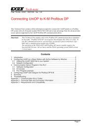
Tech-noteor more display pages that outline and control your applications. The multiple page capabilityof each panel allows any application to be broken down into as many pages as you want,depending only on the amount of memory in your target system. Completed projects can berecalled from disk or from the panel itself for further modification.For information regarding hardware operation, please see the <strong>UniOP</strong> Installation &Operation Guide(Internal <strong>Manual</strong> Code: 05.011)2 Quick Start2.1 Quick Start Tutorial IntroductionThe Quick Start Tutorial shows how the Designer software is used to develop applicationsfor the <strong>UniOP</strong> panel.Though the chosen example is very simple, it goes through all the steps that are normallyused to develop normal applications, even the most complex ones.At the end of the tutorial you will not be able to perform the single steps in detail, you will notknow all the Designer features, how and when to use them. What you will have is a generalfeeling of what is required to develop an application, which tasks have to be performed andhow easy is their execution thanks to the Designer software.Note: The tutorial assumes that you have already installed the software.2.1.1 Development Environment SetupThe above figure shows a typical, complete setup for the development of applications.Tn179-05.doc - 12.01.2007<strong>UniOP</strong> <strong>User's</strong> <strong>Manual</strong> 2
Tech-noteUser s develop their applications with the Designer software and download them into the<strong>UniOP</strong> panel. The panel in turn is connected to one or more Controllers (PLCs).The developed applications can display the Controller(s) I/Os on the <strong>UniOP</strong> panel and alsocan send commands to the connected Controller(s).The <strong>UniOP</strong> contains a software simulated Demo Controller that allows the development andtesting of applications even when real Controllers are not available.To the Quick Start Tutorial2.2 Quick Start TutorialConnect the programming cable from the PC to the panel.Connect the controller's communication cable to the panel.Locate the Designer icon on your PC desktop and click on it.Once the Designer is open, create a new project file by selecting New from the File menu.Give the new project a name, select a file location,and click OK.Tn179-05.doc - 12.01.2007<strong>UniOP</strong> <strong>User's</strong> <strong>Manual</strong> 3
Tech-noteSelect Project - Configure Controller.The currently selected controller is displayed.Click on the "..." button to select a different driver, if necessary.Press the Controller Setup button to select the particular controller model being used.Tn179-05.doc - 12.01.2007<strong>UniOP</strong> <strong>User's</strong> <strong>Manual</strong> 4
Tech-noteIf required, set up the panel-to-controller communication parameters by pressing thePLC/Drive Comm button.Set the parameters, then click on OK to confirm your selections and close the open dialogboxes.Select Project - Panel Setup. Select the type of display representative of your <strong>UniOP</strong> panel.This step could be eliminated by placing the panel in Configuration Mode and selecting GetPanel Resources from the Transfers menu.Tn179-05.doc - 12.01.2007<strong>UniOP</strong> <strong>User's</strong> <strong>Manual</strong> 5
Tech-noteYou are now ready to begin designing the project page. Click somewhere on the projectpage and, using the PC keyboard, type the words "This is a data value =" on the first page oftheproject.Select Insert - Data Fields - Numeric/ASCII. The cursor will turn into crosshairs. Use thecursor to define the boundaries of a small box following the phrase you typed on the page.The Properties dialog box will appear on the screen.Tn179-05.doc - 12.01.2007<strong>UniOP</strong> <strong>User's</strong> <strong>Manual</strong> 6
Tech-noteClick the "…" button under Reference.The Data Field Properties dialog box will appear on the screen.Fill in the Data Field Properties dialog box with the appropriate data. The data referenceMUST already exist in the controller. Keep in mind that this dialog box is controller specific.Click on the OK button in order to confirm the controller information.Click on the OK button in order to confirm the numeric field properties and create the datafield. The following figure shows the resulting screen.Select Save from the File menu.Select Transfers - Options - Serial PortsTn179-05.doc - 12.01.2007<strong>UniOP</strong> <strong>User's</strong> <strong>Manual</strong> 7
Tech-noteChoose the communications port that Designer will use to communicate with the panel.Ports that are unavailable will be grayed out. Under normal circumstances, use the followingparameters to communicate with a panel: 38400 baud, no parity, and 1 stop bit.Power up the <strong>UniOP</strong> panel and make sure it is in Configuration Mode. The panel must be inConfiguration Mode to communicate with the Designer software! When the unit is inConfiguration Mode, the words CONFIGURATION MODE will appear on the panel. If you donot see the words CONFIGURATION MODE displayed on the panel:Hold down the Enter key or touch an empty spot on the screen until the command menuappears.Use the arrow keys to highlight CONFIG or CFG and press Enter again.Select Transfers - Download from Designer to send the project to the panel.If the default setup of the Designer software has not been changed, the project will startautomatically after being downloaded.Aftera short pause, check the display:Tn179-05.doc - 12.01.2007<strong>UniOP</strong> <strong>User's</strong> <strong>Manual</strong> 8
Tech-noteThe text that wa s typed in previous step should be visible, along with the data value readfrom the controller.The Fault light should be off.The Com and Run lights (if present) should be on. A blinking Com light indicates acommunications error.3 Installation3.1 OverviewThis section provides:the assumptions and conventions used in this documentation,system requirements for using Designer,software installation instructions,instructions for solving installation problems,basic instructions for connecting a <strong>UniOP</strong> panel to the PC,contact information,technical support contacts,instructions for reporting a bug,software license and disclaimer.3.2 AssumptionsWe assume that those reading this manual are using the Designer software to design controlpanel applications to run on <strong>UniOP</strong> panels.We also assume that you have a basic understanding of PCs, Microsoft Windowstype of network environment in which you will run the application., and the3.3 ConventionsNames of menus and commands on menus are shown in bold type, as are the names ofdialog boxes. For example, "A new project may be created by selecting New fromthe FileTn179-05.doc - 12.01.2007<strong>UniOP</strong> <strong>User's</strong> <strong>Manual</strong> 9
Tech-notemenu." If the name of the command or menu is highlighted, it is linked to another topic in thehelp text. For example, "Select Get Panel Resources from the Transfers menu."Keyboard keys that you should press are shown in bold, as in "Press Enter." If two keyboardkeys are to be pressed at the same time, they are shown in bold with a plus sign (+)between them, as in "Press Ctrl+F2."Text that you are to type into a box appears in bold in a different font (Courier), for examp le,"Type D:\setup in the box."3.4 System RequirementsThe following hardware / software is required to use Designer.3.4.1 Free hard disk spaceDesigner, once installed, takes around 70 MB of hard disk space. The installation procedure(only at installation time) requires twice as much (i.e. 140 MB).3.4.2 RAM MemoryDesigner runs on systems with at least 32 MB RAM memory.3.4.3 Supported Operating Systems:W indows 98 SEWindows NT version 3.51 and aboveWindows MEWindows 2000Windows XP3.5 Software InstallationNote: Microsoft Windows must be installed before installing the Designer software.To install Designer:Close all other programs.Insert the CD-ROM into CD-ROM drive. If your system has Autorun enabled, the Designerinstallationwill start automatically. If so, skip to step 5.Tn179-05.doc - 12.01.2007<strong>UniOP</strong> <strong>User's</strong> <strong>Manual</strong> 10
Tech-noteClick on the Start button and select Run from the popup menu.Type D:\setup in the box (if your CD-ROM drive is not drive D, substitute the appropriateletter).Follow the on screen prompts.The default location for the Designer software is "c:\Program Files\Exor\Designer 6". If youprefer to have the software at a differentlocation on your hard drive, you have that option.Tn179-05.doc - 12.01.2007<strong>UniOP</strong> <strong>User's</strong> <strong>Manual</strong> 11
Tech-noteThere are two types of setup available with the Designer software. They are:Typical - The Designer software is installed with the most common options. This isrecommended for most users.Custom - You may choose the options that you want to install. This is recommended foradvanced users.The installation procedur e will create a program group entitled "Designer" within Windows .A Designer icon will be added to your desktop. Designer also appears on the Windowsstart menu under Start-Programs-Designer.3.6 Connecting the Panel to the PCYour <strong>UniOP</strong> panel should be set up according to the instructions in the <strong>UniOP</strong> Installation &Operation Guide. However, most panels are quite simple to set up. General setupinstructions include:Place the panel on a stable surface.Connect one end of an appropriate connection cable to the appropriate port on the panel.Connect the other end of the connection cable to the appropriate port on the computer.Connect one end of the power cable to the panel.Connect the other end of the power cable to the power source.If the panel was never programmed before, it should power up in Configuration Mode.Tn179-05.doc - 12.01.2007<strong>UniOP</strong> <strong>User's</strong> <strong>Manual</strong> 12
Tech-noteSee Panel Setup for information on how to initialize and set up the panel.3.7 How to Report a BugThe Designer development team is proud to present a high quality program with minimalbugs. Despite their best efforts, however, bugs do occasionally appear in the software.Should you notice a problem with the software that you think may be a bug, please report itto:techsupp@exorinternational.netPlease include as much information as possible, including a description of the irregularity,the type of PC and panel that you have, any other software that was running when theproblem occurred, and the sequence of steps that led to the problem.3.8 Technical SupportFor questions about the Designer software, contact EXOR by sending an email to thefollowing address:techsupp@exorinternational.net3.9 Contact InformationEXOR world-wide locations are listed hereafter:EXOR Electronic R&D Inc.10150 International Blvd.Cincinnati, OH 45246USAhttp:/ /www.exor-rd.comEXOR GmbHHaus Grünewald 142653 SolingenGermanyhttp://www.exor.deSitek SpAVia Monte Fiorino 9San Giovanni Lupatoto (VR)I-37057Italytechsupp@sitek.itTn179-05.doc - 12.01.2007<strong>UniOP</strong> <strong>User's</strong> <strong>Manual</strong> 13
Tech-note3.10 Designer Software LicenseThis is a legal agreement between you (either an individual or a single entity) and EXOR forthe Designer SOFTWARE, which includes computer software and may include associatedmedia, printed materials, and "on-line" electronic documentation.By installing, copying, downloading, accessing, or otherwise using the DesignerSOFTWARE, you agree to be bound by the terms of this License. If you do not agree to theterms of this agreement, do not install or use the Designer SOFTWARE; you may, however,return it to your place of purchase for a full refund.3.10.1 SOFTWARE LICENSEThe Designer SOFTWARE is protected by copyright laws and international copyrighttreaties, as well as other intellectual property laws and treaties. The Designer SOFTWAREis licensed, not sold.3.10.2 Grant of LicenseWith this License EXOR grants you the non-exclusive right to use the Designer SOFTWAREin accordance with the following terms:You may install, use, access, display, run, or otherwise interact with ("RUN") one copy ofthe Designer SOFTWARE on a single computer, workstation ("COMPUTER"). The primaryuser of the COMPUTER on which the Designer SOFTWARE is installed may make asecond copy for his or her exclusive use on a portable computer.You may also store or install a copy of the Designer SOFTWARE on a storage device, suchas a network server, used only to RUN the Designer SOFTWARE on your otherCOMPUTERS over an internal network; however, you must acquire and dedicate a licensefor each separate COMPUTER on which the Designer SOFTWARE is RUN from the storagedevice. A license for the Designer SOFTWARE may not be shared or used concurrently ondifferent COMPUTERS.The initial licensee of the of the Designer SOFTWARE may make a one-time permanenttransfer of this License and the Designer SOFTWARE only directly to an end user. Thistransfer must include all of the Designer SOFTWARE (including all component parts, themedia and printed materials and this License). The transferee of such one-time transfermust agree to comply with the terms of this License, including the obligation not to furthertransfer this License and the Designer SOFTWARE .3.10.3 LimitationsYou may not reverse engineer, decompile, or disassemble the Designer SOFTWARE,except and only the extent that such activity is expressly permitted by applicable lawnotwithstanding this limitation.The Designer SOFTWAREis licensed as a single product, its component parts may not beseparated for use on more than one COMPUTER.Tn179-05.doc - 12.01.2007<strong>UniOP</strong> <strong>User's</strong> <strong>Manual</strong> 14
Tech-note3.10.4 COPYRIGHTAll title and copyrights in and to the Designer SOFTWARE (including but not limited to anyimages, photographs, animations, video, audio, music and text incorporated into theDesigner SOFTWARE), the accompanying printed materials, and any copies of the Designerare owned by EXOR or its suppliers. If this Designer SOFTWARE contains documentationwhich is provided only in electronic form, you may print one copy of such electronicdocumentation. You may not copy the printed materials accompanying the DesignerSOFTWARE.3.10.5 INTELLECTUAL PROPERTYThe Intellectual Property of the Designer SOFTWARE (including but not limited to anyimages, photographs, animations, video, audio, music and text incorporated into theDesigner SOFTWARE) is owned by EXOR.3.10.6 DISCLAIMER (Limited Warranty)The Designer SOFTWARE is provided "as is" and without warranty of any kind, express,implied or otherwise, including without limitation, any warranty of merchantability or fitnessfor a particular purpose.In no event shall EXOR be liable for any special, incidental, indirect or consequentialdamages of any kind, or any damages whatsoever resulting from loss of use, data or profits,whether or not advised of the possibility of damage, and on any theory of liability, arising outof or in connection with the use of the Designer SOFTWARE.4 Reference4.1 File Menu4.1.1 File MenuThe File menu contains familiar Windows commands for managing files and printing.NewOpenCloseSaveSave AsPrintTn179-05.doc - 12.01.2007<strong>UniOP</strong> <strong>User's</strong> <strong>Manual</strong> 15
Tech-notePrint PreviewExport to TagDBExport StringsImport StringsRecent FilesExit4.1.2 NewA new project may be created by selecting New from the File menu, by clicking the New Fileicon, or by pressing the Ctrl+N keys. This opens the New Project dialog box.Enter a name for the new project and select the file location on the PC where the project fileis to be stored. Click on an icon to identify the type of project file to be created. Unlessotherwise specified, Designer files are assumed to have the .dpr extension.When a new Project file is created, the current project configuration is carried over for usewith the new project. This approach relieves you from having to reset the panel andcontroller parameters each time a new project is created. The latest configuration is savedon exit for use the next time Designer is started.When you switch between two projects with different configurations, the latest project to beopened overrides the previous and becomes the new default state for the Designer.To prevent accidental reset of the configuration parameters, you are prompted to confirm theNewoperation if there are pending modifications that have not been saved.Tn179-05.doc - 12.01.2007<strong>UniOP</strong> <strong>User's</strong> <strong>Manual</strong> 16
Tech-note4.1.3 OpenTo open an existing project, select Open from the File menu, click the Open icon on thetoolbar, or press the Ctrl+O keys. The Open Project dialog box will appear, providing a listof the file names in each directory.Enter the name of the file to be loaded or use the list box to select from the existing files. Ifan extension is not specified, .dpr is assumed.4.1.4 CloseTo close a currently open file, select Close from the File menu.Files may also be closed by clicking on the lower of the two "X"s in the upper right-handcorner of the Designer window, by selecting Close from the Designer menu, or by pressingCtrl+F4.4.1.5 SaveTo save a project, select Save from the File menu, click on the Save file icon on the toolbar,or press the Ctrl+S keys.The cursor may be momentarily replaced with an hourglass while the file is saved.If the application has not been named, the Save As dialog box will appear instead.4.1.6 Save AsIf an application to be saved has not been named, the Save Project As dialog box appears.Or, you may select Save As from the File menu. This option can also be used to save aproject under a differentname.Tn179-05.doc - 12.01.2007<strong>UniOP</strong> <strong>User's</strong> <strong>Manual</strong> 17
Tech-noteThe Save Project As dialog box shows the current directory path and the current file name.A new name and path may be entered or the ones presented may be accepted.Files may be saved as file format "*.dpr" (Designer files) or "*. rom" (Designer ROM files). Ifno extension is specified, "*.dpr" is assumed.If the file already exists in the selected directory, you are prompted to confirm the Save Asoperation in order to overwrite the existing file.4.1.7 PrintThe Print command in the File menu refers to printing from the Designer software, whereasthe print items in the Project menu are used to set up print functionality in the <strong>UniOP</strong> panels.Selecting Print from the File menu (or pressing the Ctrl+P keys) brings up the Print Setupdialog box, from whichthe Designer project information may be printed.4.1.8 Print PreviewSelecting Print Preview from the File menu brings up the Print Setup dialog box, fromwhich the Designer project information may be previewed for printing.4.1.9 Designer Print SetupDesigner contains a printing routine for printing project file information. This module is ableto print graphical previews of the project pages, variable cross-references and much more!Selecting File-Print or File-Print Preview will bring up the following dialog box.Tn179-05.doc - 12.01.2007<strong>UniOP</strong> <strong>User's</strong> <strong>Manual</strong> 18
Tech-notePrint (or Print Preview)Start (or view) the print operation.Printer SetupOpen the standard Windows Printer Setup dia log box. Printer to use, page size, pageorientation, etc. can be selected from this dialog box.CancelClose the dialog box without executing the print operation.Panel Page RangeDefine which panel pages need to be included in the printout.All pagesPagesAll data on all panel pages are printed.Only the data that is inside the selected pages are printed.To specify the panel pages to print, the user needs to enter the pagesequence to print. A page sequence is a page range separated bycommas (i.e. 4-5, 8, 13-20). Valid ranges are a single page only, i.e. 8,or consecutive pages, i.e. 4-5.Without page breaksAny new data section starts a new page. By selecting this checkbox, all data will becompressed on as little number of pages as possible.Suppress all cover pagesThis checkbox should be selected if the user wants to suppress the cover pages.Hide empty tablesUse this checkbox if the user wants to avoid printing tables relative to data sections thatwere not configured inside the project.Tn179-05.doc - 12.01.2007<strong>UniOP</strong> <strong>User's</strong> <strong>Manual</strong> 19
Tech-noteSave change on exitWhen this checkbox is marked, the selected Report Data Set will be saved for future use.Report data setsThis section of the print dialog box contains the list of project data that could be printed. Forany items that are listed, a checkbox gives the user the possibility to enable or disable thetable printout.Project informationGeneric project information. It contains the project name, panel type and name of thecontroller being used.Project SummaryContains some statistical information such as the project file size, number of pages, numberof used pictures, etc.<strong>UniOP</strong> page layout description dataList of page objects.<strong>UniOP</strong> Page descriptionDescription of the pages in the project.Panel Key MacrosLocal macro keys.PicturesStatic images.Touch CellsList of graphic components: Object-oriented touch cells, Trends, Gauges.Data FieldsList of PLC data field items.RecipesRecipe data set values.Global Key MacrosGlobal macro keys.Trend BuffersTrend buffer parameters.RecipesTable with list of recipes that have the Multipage flag set.Data TransferData transfer jobs.Reserved Data AreaRDA parameters.AlarmsAlarm table with messages.Tn179-05.doc - 12.01.2007<strong>UniOP</strong> <strong>User's</strong> <strong>Manual</strong> 20
Tech-noteDesigner SetupPanel Printer and ReportsPrinter setting and print report table parameters.Panel SetupList of panel capabilities and setup configurationController and Network SetupList of controller drivers connected on the panel network.Remote Pass throughRemote Pass through parameters.PasswordTable with list of all defined passwords and their parameters.Cross ReferenceList of Pages, Pictures and Controller references with page references.Report ContentsTable of the Report Contents with page numbers4.1.10 Export to tag databaseThis option is used to export all the tags defined in the currently opened project to adatabase specified by the user. If the project doesn't have any tags associated with it, thisoption will be disabled.4.1.11 Export StringsStrings used in a project can be exported into a CSV (Comma Separated Values, a dataformat used by various applications, e.g. Microsoft ExcelTM) file by selecting Export Stringsfrom the File menu.This opens the Export Strings dialog box.Tn179-05.doc - 12.01.2007<strong>UniOP</strong> <strong>User's</strong> <strong>Manual</strong> 21
Tech-noteThe information stored in the file has the following format:#-------------------------------------------------------------------# Filename: DemoFul2.csv# Created: Friday, May 03, 2002 - 10:49# Project: C:\Designer Projects\DemoFul2.dpr#-------------------------------------------------------------------2, """English - Default""","""French"""PG-1,"" "Main Menu""","""Menù Pri."""ST-1-1,"""Created by EXOR""","""Créé par EXOR"""ST-1-2,"""<strong>UniOP</strong> Project Functionality""",""""""ST-1-3,"""Tech Support Tel. ...""","""Tech Support Tel. ..."""The first section contains information about the exported file: its name, the date of creationand the original project file.The second section specifies the number of languages and their names.The third section contains a line for each string in the project. Each line contains a stringidentifier (not to be modified), then the string value for each one of the different languagessupported by the project.This way it is possible to modify the strings stored in a given project.ANSI / Unicode Encoding is supported.Using Unicode feature characters of different languages can be added in the projects pageby editing the string value of the exported file.RestrictionsUnicode character is definedusing two bytes, this means we can have until 65.536 differentcharacters. <strong>UniOP</strong> panel, instead, can manage 256 characters code. Using the Unicodefeature you have the possibility to mapping a subset of 256 Unicode characters inside the<strong>UniOP</strong> panel.Tn179-05.doc - 12.01.2007<strong>UniOP</strong> <strong>User's</strong> <strong>Manual</strong> 22
Tech-noteTypical applicationTo enable Unicode support it is necessary modify the panel font file to have some Unicodecharacters inside. For example you can use ANSI characters inside the first 128 bytes andRussian (Unicode) characters inside the other 128 bytes. Then you have to configure thenew 2unicode parameter inside the display32.ini file to define the ANSI code (256) UniCode (65.536) character correspondence. Example is shown below:[RUSSO Font]BargraphStart=226BoxChars=218,191,192,217,196,179,196,179,180,194,193;201,187,200,188,205,186,205,186,0,0,0BigCharStart=128Linefeed=1272Unicode=0x8F,0x0444;0x90,0x0438;0x91,0x0441;0x92,0x0432;Note: Modifying the string length has an effect on the real state occupied by that string onthe screen.4.1.12 Import StringsIt is possible to upload to a project the strings previously saved in a CSV (Comma SeparatedValues, a data format used by various applications, e.g. Microsoft ExcelTM) file by selectingImport Strings from the File menu.This opens the Import Strings dialog box.Note: the Import Strings operation may upload a set of strings into the project that are eitherincompatible or have problems. Before attempting this operation it is recommended tosave/backup the strings currently in use by calling the Export Strings function.Tn179-05.doc - 12.01.2007<strong>UniOP</strong> <strong>User's</strong> <strong>Manual</strong> 23
4.1.13 Recent FilesTech-noteThe most recently opened files are listed under the File menu as a shortcut. Click on thename of a file to reopen it.4.1.14 ExitSelecting Exit from the File menu can be used to terminate the Designer program. You areprompted to confirm the operation if the current application has not been saved.4.2 Edit Menu4.2.1 Edit MenuThis section provides information about the Edit menu. The Edit menu contains manyfamiliar Windows commands for working with text and objects on the page.CutCopyPasteAlignMake Same SizeSelect AllFonts4.2.2 UndoThe Undo command reverses the last action. This action can also be activated by pressingthe Ctrl+Z keys.4.2.3 RedoThe Redo command reapplies the actions that were previously canceled by the Undocommand. This action can also be activated by pressing the Ctrl+Y keys.4.2.4 CutThe Cut command removes the selected item from the current page and places it on theWindows clipboard. This action can also be activated by pressing the Ctrl+X keys.Tn179-05.doc - 12.01.2007<strong>UniOP</strong> <strong>User's</strong> <strong>Manual</strong> 24
Tech-note4.2.5 CopyThe Copy command makes a copy of the selected item from the current page and places iton the Windows clipboard. This action can also be activated by pressing the Ctrl+C keys.4.2.6 PasteThe Paste command places items from the Windows clipboard onto the current page atthe current position of the cursor. This action can also be activated by pressing the Ctrl+Vkeys.4.2.7 Select AllThe Select All command selects all of the various items on a page. This makes it easy tocut, copy, or paste a group of objects.4.2.8 Align4.2.9 AlignUse the Align commands on the Edit menu to arrange objects/items on a page.Select an object or item by single-clicking on it, then hold down the Shift key while clickingon other objects or items to be aligned with it. When all of the objects or items to be alignedare selected, choose one of the commands in the Align submenu.LeftHoriz CenterRightTopVert CenterBottomNote: Objects/items are aligned with the last created or inserted object/item.4.2.10 LeftAligns the left sides of the objects/items with the left edge of whichever object/item wasselected first.Tn179-05.doc - 12.01.2007<strong>UniOP</strong> <strong>User's</strong> <strong>Manual</strong> 25
Tech-note4.2.11 Horiz CenterAligns the horizontal center points of the objects/items with the horizontal center point ofwhichever object/item was selected first.4.2.12 Align RightAligns the right sides of the objects/items with the right edge of whichever object/item wasselected first.4.2.13 Align TopAligns the top edges of the objects/items with the top edge of whichever object/item wasselected first.4.2.14 Align Vert CenterAligns the vertical center points of the objects/items with the vertical center point ofwhichever object/item was selected first.4.2.15 Align BottomAligns the bottom edges of the objects/items with the bottom edge of whichever object/itemwas selected first.4.2.16 Make Same Size4.2.17 Make Same SizeUse the Make Same Size commands from the Edit menu to match the size of objects/itemson a page.Select an object or item by single-clicking on it, then hold down the Shift key while clickingon other objects or items to be resized. When all of the objects or items to be resized areselected, choose one of the commands in the Make Same Size submenu.WidthHeightBothNote: Objects/items are resizedto match the size of the last created or inserted object/item.Tn179-05.doc - 12.01.2007<strong>UniOP</strong> <strong>User's</strong> <strong>Manual</strong> 26
Tech-note4.2.18 Make Same Size WidthResizes objects/items so that the width matches the width of whichever object/item wasselected first.4.2.19 Make Same Size HeightResizes objects/items so that the height matches the height of whichever object/item wasselected first.4.2.20 Make Same Size BothResizes objects/items so that both the width and height matches the width and height ofwhichever object/item was selected first.4.2.21 Fonts4.2.22 FontsDesigner makes it easy to select a font that will appear to advantage in a particular project.There are two types of fonts in Designer: Panel Fonts and Objects Fonts.Panel fonts are character based type of fonts and are supported by all type of panels.Object Fonts are based on bit maps and are supported only by graphics panels.4.2.23 Panel Font4.2.24 Panel FontsIt is possible to have up to four (4) different panel fonts on certain <strong>UniOP</strong> panels. The SelectFont dialog box lets you select a font for onscreen text from a pull-down list.Tn179-05.doc - 12.01.2007<strong>UniOP</strong> <strong>User's</strong> <strong>Manual</strong> 27
Tech-noteNote: If a project file contains panel font components, switching to a standard font (not anenhanced font) will erase all of the panel font components in the project.Font NameFont Size4.2.25 Font NameSelect a panel font for the on-screen text from the pull-down list.Font EditorInstalling New Panel Fonts4.2.26 Font SizeThe Font Size buttons can be used to change the character size of any text or variable field.Font size choices include Regular, Regular, Large or Extra Large. Regular characters aresimply a single character.Double characters are twice the size of a regular character (2x2). Large characters are fourtimes the size of a regular character (4x4).Extra large characters are eight times the size of a regular character (8x8).Note: When the area defined for a text box is too small, only the sizes that can fit inside theselected area are enabled.Tn179-05.doc - 12.01.2007<strong>UniOP</strong> <strong>User's</strong> <strong>Manual</strong> 28
4.2.27 Objects FontTech-note4.2.28 Objects FontThe Font dialog box lets you select the default font for all graphic objects (meters, trends)and the touch cells.FontFont StyleSizeEffectsSampleScript4.2.29 Objects Font FontChoose a font from the pull-down list. New fonts may be added just like any other True-Typefont; by opening Fonts from the Windows Control Panel and using the Install New Fontcommand from the File menu. (This is the Windows Control Panel File menu, not theDesigner File menu.)4. 2.30 Objects Font StyleTextmay be bold, italic, or both.Tn179-05.doc - 12.01.2007<strong>UniOP</strong> <strong>User's</strong> <strong>Manual</strong> 29
4.2.31 Objects Font SizeSelect a font size, in points.Tech-note4.2.32 Objects Font EffectsText may be displayed as strikeout or underlined. It is also possible to display text in variouscolors.4.2.33 Objects Font SampleThe sample window gives a preview of the selected text settings.4.2.34 Objects Font ScriptWestern and various other scripts (Hebrew, Greek. Cyrillic, etc.) are available.4.3 View Menu4.3.1 View MenuThis section provides information about the View menu. The View menu lets you set thescreen to view the project in the most comfortable manner for various tasks. Commands onthe View menu include:Zoom InZoomOutStatus BarToolbarsWorkspaceFull ScreenGraphics Library ManagerLayers4.3.2 Zoom InZoom In enlarges items on the screen, although the whole project page may no longer bevisible.This is useful for checking fine details. You can also access this feature by pressing the Ctrlkey with the + key of the numeric keypad.Tn179-05.doc - 12.01.2007<strong>UniOP</strong> <strong>User's</strong> <strong>Manual</strong> 30
Tech-noteUsers can define the view size as a % of the panel size as shown in the above figure. Theycan pick the percentage from the combo box or pick the best fit or specify any % (within validrange). Zoom size will be changed to best fit once the Panel setup is changed.4.3.3 Zoom OutZoom Out makes more of the screen area visible, although items on the screen will appearsmaller. This is useful for getting an overall view of the page. You can also access thisfeature by pressing the Ctrl key with the - key of the numeric keypad.4.3.4 Status BarThe status bar across the bottom of the Designer screen provides interactive information onvarious screen items.If Status Bar is checked in the View menu, the status bar will be visible across the bottom ofthe screen. To hide the status bar, uncheck it under the View menu. To make it visible again,simply check it again.Tn179-05.doc - 12.01.2007<strong>UniOP</strong> <strong>User's</strong> <strong>Manual</strong> 31
Tech-note4.3.5 Toolbars4.3.6 ToolbarsThe Toolbars dialog lists the various toolbars displayed for the current project. These mayinclude the following:Primary toolbar - typically provides shortcuts to commonly used Windowscommands.-typeSecondary toolbar - typically provides shortcuts to Designer project-level commandsFull Screen toolbar - typically provides shortcuts to viewing preferencesTools toolbar - typically provides shortcuts to user-specified toolsTouchScreen toolbar - typically provides shortcuts to touchscreen-specific commandsCommands available from the Toolbars dialog box include:Toolbar NameShows the name of the selected toolbar.Tn179-05.doc - 12.01.2007<strong>UniOP</strong> <strong>User's</strong> <strong>Manual</strong> 32
Tech-noteShow TooltipsProvides a short description of a toolbar icon when the cursor pauses above the icon.Cool LookGives the buttons on the toolbars an invisible edge, making for a smoother appearance onthe toolbars.Large ButtonsMakes the buttons appear twice as large as normal for easier viewing and use.NewReset/DeleteThe Reset button returns the toolbars to their default state.If you have added any toolbars, the Reset button becomes a Delete button so that useraddedtoolbars can be removed.DefaultClick the Default button to align and dock the toolbars to the installed state. It also reloads allbuttons on the toolbar.4.3.7 NewThe New button brings up the New Toolbar dialog box, where you may enter the name of anew toolbar to be created.The new toolbar may then be placed in a location of your choice in the toolbar section of theDesigner screen.Tn179-05.doc - 12.01.2007<strong>UniOP</strong> <strong>User's</strong> <strong>Manual</strong> 33
4.3.8 WorkspaceTech-noteThe status bar to the left of the main Designer screen provides information on project pagesand lists various graphics and objects that can be placed in a project. If Workspace ischecked in the View menu, the workspace will be visible.The default position of the workspace is to the left of the main Designer screen, however theworkspace can be moved anywhere on the Designer screen. To hide the workspace,uncheck it under the View menu. To make it visible again, simply check it again.Note: Right-clicking in the frame of the workspace box brings up a number of options forviewing the workspace. Select Allow Docking to dock the workspace against any of the foursides of the application. If the check box is removed, then the workspace will act as a miniwindow,which can be placed anywhere and resized. On the other hand, clicking Float inmain window causes the workspace to occupy the entire application window and minimizethe graphics view.4.3.9 Full ScreenThe Full Screen command in the View menu (and the Full Screen icon) enlarges theDesigner screen to occupy the full screen size.A small toolbar remains on the screen with Full Screen, Zoom In, and Zoom Out icons to letyou easily select other viewing options.Clicking on the Full Screen icon again takes Designer out of Full Screen view.Tn179-05.doc - 12.01.2007<strong>UniOP</strong> <strong>User's</strong> <strong>Manual</strong> 34
4.3.10 Graphics LibraryTech-note4.3.11 Graphics Library ManagerThe Graphics Library Manager dialog box provides an easy way to work with graphicslibraries.The dialog box has three tabs:Project - shows the graphics libraries currently used in the projectLibrary - shows the graphics libraries currently installed and accessible to DesignerDisk - allows to work with file system to load, save graphic files.Tn179-05.doc - 12.01.2007<strong>UniOP</strong> <strong>User's</strong> <strong>Manual</strong> 35
Tech-note4.3.12 ProjectThis tab allows the user to see how many graphic symbols are present in the project and, ifneeded, to change their names.The button Import puts the currently selected graphic symbol into the Project Screen area.Tn179-05.doc - 12.01.2007<strong>UniOP</strong> <strong>User's</strong> <strong>Manual</strong> 36
Tech-note4.3.13 LibraryThis tab allows to modify/update the contents of the graphics library.The tab contains a toolbar providing access to the familiar Windows commands of cut,copy, paste, rename, delete, and insert folder for graphics management. A Properties iconleading to a dialog box with the properties of the currently selected graphic symbol is alsoavailable.Users, if needed, can changethe name of the graphic symbols used in the project.The button Import puts the currently selected graphic symbol into the Project Screen area.Tn179-05.doc - 12.01.2007<strong>UniOP</strong> <strong>User's</strong> <strong>Manual</strong> 37
Tech-note4.3.14 DiskThis tab allows to select a new graphic symbol (a new picture) from the file system.The button Import puts the currently selected graphic symbol into the Project Screen area.4.3.15 Layers4.3.16 LayersEach <strong>UniOP</strong> page is actually divided into layers. Layers define a set of planes, stackedalong the Z-axis of the screen, i.e. the axis that goes form the screen to the eye of theuser/observer. Thanks to layers it is possible to control in an easy way the Z-ordering (that isthe position along the Z-axis) of a group of objects and graphics. For instance, by changingthe position of a layer relative to the others, also the position of all the objects and linesbelonging to that layer are modified.Objects and graphics are inserted into the currently active layer. The active layer can beselected by using the layers toolbar (usually positioned at the bottom of the work area).The layers dialog controls how layers are displayed, allows to create new layers, deletethemand change their reciprocal order.Tn179-05.doc - 12.01.2007<strong>UniOP</strong> <strong>User's</strong> <strong>Manual</strong> 38
Tech-noteThese are the available commands:InsertDeleteMove Item UpMove Item DownShow and Lock Active LayersOnly Show Active LayersNote: Layers are a Designer feature introduced to easily configure the Z-ordering of objectsand graphics on the panel screen. The <strong>UniOP</strong> panel only supports the relative Z-ordering ofobjects and graphics (no layers).4.3.17 InsertInserts a new layer.Tn179-05.doc - 12.01.2007<strong>UniOP</strong> <strong>User's</strong> <strong>Manual</strong> 39
Tech-note4.3.18 DeleteDeletes the selected layer.4.3.19 Move Item UpMoves the layer occupied by an item forward.4.3.20 Move Item DownMoves the layer occupied by an item downward.Tn179-05.doc - 12.01.2007<strong>UniOP</strong> <strong>User's</strong> <strong>Manual</strong> 40
Tech-note4.3.21 Show and Lock Active LayersThe Show option controls if a given layer can be displayed or not.The (Un)Lock option controls if a layer can be moved.4.3.22 Only Show Active LayersThis option makes Designer show only the active layers.4.4 Insert Menu4.4.1 Insert MenuThis section provides information about the Insert menu. The Insert menu gives you themeans to easily place text and/or objects onto a project page. Some of these objects, suchas numeric fields or bar graphs display information from the controller. Other objects, suchas the various types of touch cells, allow a panel user to interact with the panel.TextBitmapData FieldsTn179-05.doc - 12.01.2007<strong>UniOP</strong> <strong>User's</strong> <strong>Manual</strong> 41
Tech-noteTouch CellsShapesTrend WindowMeter InstrumentTrend Time FieldRecipe MenuSpecial CharactersImport Bitmap Graphics4.4.2 TextTo insert a Text Field, either click on the Text icon in the toolbar or select Text from theInsert menu. Use the cursor to specify the location of the text box. Once a text box iscreated, click to place the cursor inside the text box and type the text that is to be inserted.Note: The text uses the font selected in the Select Font dialog box. This dialog box can beaccessed by clicking on the Font icon in the toolbar or by selecting Edit - Fonts - Panel Font.The font must be specified before the text is created. If the font is too large for the selectedarea, Designer will not allow the text to be entered.To edit a text field, select the field by left-clicking on it, then right-click on the text fieldbring up an edit menu for the text field. Text can be cut, copied, or pasted, edited,foreground and background colors can be set, or text can be resized.to4.4.3 BitmapTo insert a custom bitmap image, either click on the Bitmap icon in the toolbar or selectBitmap from the Insert menu. Use the cursor to specify the location of the bitmap image. TheBitmap Editor dialog box then appears.Tn179-05.doc - 12.01.2007<strong>UniOP</strong> <strong>User's</strong> <strong>Manual</strong> 42
Tech-noteA sliding bar lets you zoom in or out for easier editing. Familiar Windows drawing tools areavailable to create a custom bitmap image.On invoking the Foreground color and Transparency color button of Bitmap editor dialog willpopup a palette with 16 colors and a "More Colors ... " button as shown in the belowfigures.On invoking the More Colors button a 256 color palette (If 256 colors are supported) dialogis shown. From the this the user can select the required palette. When the mouse is over aparticular color box RGB values of the same is shown as tooltip as shown in the followingfigure.Tn179-05.doc - 12.01.2007<strong>UniOP</strong> <strong>User's</strong> <strong>Manual</strong> 43
Tech-note4.4.4 Data Fields4.4.5 Data FieldsData fields are those items that the Designer software uses to display information from thecontroller.These dynamic data items come in the form of numeric fields (which can be displayed innumeric format or in ASCII format), bargraphs, message fields, attributes, dynamic graphics,time, and date fields.These fields can be created by either selecting one of the seven types of fields from theData Fields submenu in the Insert menu or by clicking on the various data field icons in thetoolbar. This brings up the data Field Properties dialog box for the appropriate data fieldtype.4.4.6 Numeric/ASCII4. 4.7 Numeric/ASCII Data FieldsThis option is used to add a numeric data field or an ASCII data field to the current page. Anumeric data field reflects a numeric value read from the controller. An ASCII data fielddisplays a character string read from the controller. (An ASCII data field differs from a plaintext field in that an ASCII data field interacts with the controller whereas plain text is a staticscreen item.)Tn179-05.doc - 12.01.2007<strong>UniOP</strong> <strong>User's</strong> <strong>Manual</strong> 44
Tech-noteA numeric/ASCII data field can be created by either clicking on the Numeric Field icon in thetoolbar or by selecting Insert - Data Fields - Numeric/ASCII. Use the cursor to specify thelocation of the item.Once the numeric/ASCII field is created, the Numeric Field Properties dialog box will appear.A number of items can be configured from this dialog box. They are grouped in the followingtabs:GeneralTextRangeScalingAttributesAn external small window allows to Preview the data files. A placeholder of 9's is used toindicate the presence of an numeric data field in Designer, while a placeholder of A'sindicates an ASCII data field.4.4.8 PreviewIf a numeric format is chosen, the field will be represented by 9's the panel. If an ASCIIformat is chosen, the field will be shown as A's on the display. If Reference is set to Variable,Tn179-05.doc - 12.01.2007<strong>UniOP</strong> <strong>User's</strong> <strong>Manual</strong> 45
Tech-notethe field is shown as C's on the display. If Reference is set to Recipe, the field is shown asR's on the display.4.4.9 General4.4.10 General tabThe Style, Format, and Size portions of this dialog box are not controller specific. Theseareas are used to instruct the panel in the manner in which to display the data.The Reference area is controller specific.Tn179-05.doc - 12.01.2007<strong>UniOP</strong> <strong>User's</strong> <strong>Manual</strong> 46
Tech-note4.4.11 StyleYou can choose a numeric data field that displays numbers or an ASCII data field thatdisplays ASCII characters.4.4.12 FormatFormatThe Format area allows you to format the data field. These choices will vary according to thecapabilities of your controller.Format choices for Numeric/ASCII data fields includeTn179-05.doc - 12.01.2007<strong>UniOP</strong> <strong>User's</strong> <strong>Manual</strong> 47
Decimal/HexadecimalSigned/UnsignedTech-noteFixed Point Placement.Decimal Hexadecimal BaseYou can choose between a decimal base (base 10) or a hexadecimal base (base 16).Note: When the Reference is set to Recipe, the initial values entered for a particular Recipedata field will be in the format specified for that data item. For example, if a numeric formatof Hexadecimal is entered for a Recipe data field, then all the values entered in the RecipeConfiguration dialog box for this Recipe data field will be in hexadecimal. A value of 10entered in a Recipe Configuration dialog box under these circumstances will be interpretedas 10 hexadecimal.Signed / UnsignedOptions are Signed or Unsigned data format. Supposing the variable's data area has alength of N bits, if the Unsigned option is chosen the variable is interpreted as an integerranging from 0 to 2N - 1. If the Signed option is chosen the variable is interpreted as a twocomplement integers ranging from - 2N-1 to 2N-1 - 1. These choices are only active whenthe specified controller supports signed/unsigned data format.Fixed Point PlacementThe fixed point option permits you to select how many decimal points, if any, are displayedon the panel. This feature parallels with scaling. Enter the number of decimal places to bedisplayed in the Placement box.Note: Keep in mind that the decimal point will take up one position in the field (i.e., a fieldwith a width of four and a placement of 1 can display at most the number 99.9).4.4.13 SizeThis is the width and height of the field. Each number or letter is one unit wide. Numbers areone unit high as well.Tn179-05.doc - 12.01.2007<strong>UniOP</strong> <strong>User's</strong> <strong>Manual</strong> 48
Tech-noteNote: The field width/height cannot exceed the width/height of remaining panel from thecurrent cursor row/column position.Note: Size is adjusted depending on the current font size. Double font takes twice thewidth/height of regular font size, etc.4.4.14 ReferenceReferenceThe Reference area is the memory location in the controller to be used, and is dependentupon the type of controller selected. The field data type, data format, and address referenceare all configured in this area. Only the items pertaining to the controller type and file typewill be configurable.Reference choices for numeric data fields include PLC, Variable, Recipe, and Index. Indexreferences are not available for ASCII data fields.Data Field PropertiesThis feature can be accessed by selecting the "…" button whenever a PLC, Variable, orRecipe reference is set. (If Index is selected, a similar box named Indirect Addressing Fieldsappears.)The contents of the Data Field Properties dialog box will vary depending upon the type ofcontroller being used andthe type of reference specified. Elements to be configured mayinclude the File or Data Type, the Data Format, File or Page Number, Element, Offset, andLeft/Right Byte. These options let you configure responses to the controller memory location.PLCThe internal PLC (programmable logic controller) installed on a <strong>UniOP</strong> panel is conceptuallyspeaking a special UniNet node. The appearance of the PLC Data Field Properties dialogbox depends on the internal controller setup but will always be according to the UniNetconfiguration style.Tn179-05.doc - 12.01.2007<strong>UniOP</strong> <strong>User's</strong> <strong>Manual</strong> 49
Tech-noteTo configure the PLC data field properties, either click on the appropriate icon in the toolbaror select Numeric/ACSII, Bargraph, Message, Attribute, or Dynamic Graphics from Insert -Data Fields, then use the cursor to specify the location of the item. In the Properties dialogbox click the PLC radio button under Reference and then click on the "…" button.See Data Field Properties for more information regarding the configuration of data fieldproperties.VariableVariableControl variables are special data items stored in the <strong>UniOP</strong> panel memory that offer ameans of controlling and monitoring recipes. You can control certain operations of the panelby modifying the values held in these internal variables. Elements to be configured includethe data type, the data format, page number, and address. These options allow you toconfigure responses to the controller memory location.To configure Variable data field properties, select Numeric/ACSII, Bargraph or Messageunder Insert - Data Fields, then use the cursor to specify the location of the item. TheProperties dialog box appears. Click the Variable button under Reference and then click onthe "..." button to configure the data field properties for control variables.Tn179-05.doc - 12.01.2007<strong>UniOP</strong> <strong>User's</strong> <strong>Manual</strong> 50
Tech-noteNote: To change properties of an existing variable data field, right-click on the data field andselectProperties.There are various types of control variables:Recipe File StatusRecipe Parameter Set SelectionRecipe ActionData Entry StatusData Entry Field NumberLanguagePasswordRecipe KeyRecipe Page for SelectionPassthrough StatusInternal VariableRecipe/Event BackupPLC Port ModePC/Printer Port ModePLC Port Module NumberPC/Printer Port Module NumberRecipeFile StatusTn179-05.doc - 12.01.2007<strong>UniOP</strong> <strong>User's</strong> <strong>Manual</strong> 51
Tech-noteIn the <strong>UniOP</strong> panel memory there is a single memory location that is used to store the statusof the entire recipe data in the panel. This memory location is called the Recipe File Status.The Recipe File Status cannot be modified by the panel's user; it is controlled by the internallogic in the panel.The Recipe File Status can take on only 2 values, 0 or 1. A value of 0 indicates that all of therecipe data for every page in the project is valid. A value of 1 indicates that an error in somepart of the recipe data was found. This means that the integrity of the recipe data iscompromised. It is very rare for this to happen, but it can feasibly occur if the <strong>UniOP</strong> panel ispowered off while the user is modifying the value of a recipe data field.If the Recipe File Status has a value of 1, the panel's user must physically change the valueof one of the recipe data items to reset the Recipe File Status to 0. Until this occurs, the userwill not be able to perform recipe transfers.Recipe Parameter Set SelectionThe <strong>UniOP</strong> panel reserves a separate memory location for the Recipe Parameter SetSelection for each recipe page. The Recipe Parameter Set Selection memory location storesthe numeric identifier of the currently selected recipe parameter set for the recipe page.Recipe Parameter Set Selection data fields can be used to visually display the currentlyselected recipe parameter sets of the various recipes in the project. When these data fieldsare added to a project, they must specify which recipe is to be monitored by the data fields.This is done by specifying the page number that contains the required recipe in the DataField Properties dialog box.For example, a project might contain three recipes, one on page 2, one on page 3 and theother on page 7. To monitor the currently selected recipe parameter sets of these threedifferent recipes, thr ee Recipe Parameter Set Selection data fields must be added to theproject. One of these data fields will be used to monitor the recipe on page 2, one to monitorthe recipe on page 3 and the third to monitor the recipe on page 7. These three RecipeParameter Set Selection data fields could all be placed on any page of the project.Regardless of where they are placed in the project, the address of the first data field wouldbe Recipe Parameter Set Selection 2, the address of the second data field would be RecipeParameter Set Selection 3 and the address of the third data field would be RecipeParameter Set Selection 7.Tn179-05.doc - 12.01.2007<strong>UniOP</strong> <strong>User's</strong> <strong>Manual</strong> 52
Tech-noteYou can also change the parameter set of a recipe on a particular page by modifying thevalue held in the Recipe Parameter Set Selection variable. This is done in the same way aschanging the value of a normal controller data field. For example, to make recipe parameterset number 3 the current parameter set, enter a value of 3 in the appropriate RecipeParameter Set Selection variable. In order to do this, the Recipe Parameter Set Selectionvariable must be set as a Read/Write variable on the Range tab of the Properties dialog boxunder Insert - Data Fields - Numeric/ASCII, Bargraph, or Message.Recipe ActionFor each page that contains a recipe, the <strong>UniOP</strong> panel reserves a separate memory locationfor the Recipe Action for that recipe page. The Recipe Action memory location stores thecurrent status of operation of the recipe for the page.Recipe Action data fields can be added to the project. These data items can then be used tovisually display the current state of the various recipes in the project.When these data items are added to the project, they must specify which recipe is to bemonitored by the data item. This is done by specifying the page number that contains therequired recipe in the Data Field Properties dialog box.A Recipe Action data field can take on only 3 values: 0, 1 or 2.A value of 0 indicates that the recipe is in its normal state of operation. In this mode ofoperation, the values of the recipe data fields are displayed on the screen of the panel andthe values of the recipe data fields can be modified.A value of 1 indicates that the recipe data for the currently selected parameter set is beingtransferred to the controller. When the transfer is complete the value is automatically reset to0.A value of 2 indicates that the recipe data for the currently selected parameter set is beingtransferred to the panel. When the transfer is complete the value is automatically reset to 0.You can start a recipe transfer by entering a value of 1 or 2 for the Recipe Action data item.By entering a value of 1, you can force the <strong>UniOP</strong> panel to send the recipe data for thecurrently selected parameter set to the controller. By entering a value of 2, you can force thecontroller to transfer the recipe data for the currently selected parameter set to the panel.DataEntry StatusTn179-05.doc - 12.01.2007<strong>UniOP</strong> <strong>User's</strong> <strong>Manual</strong> 53
Tech-noteThis control variable will be set to a 1 while the <strong>UniOP</strong> panel is in Data Entry Mode. In allother modes it will be set to 0.Data Entry Field NumberThis control variable simply contains the field number of the selected data entry fieldwhenever the panel is in Data Entry Mode.LanguageTn179-05.doc - 12.01.2007<strong>UniOP</strong> <strong>User's</strong> <strong>Manual</strong> 54
Tech-noteIn order to change the language that the project file uses once it has been downloaded tothe <strong>UniOP</strong> panel, you can create a control variable with a data type of Language. Make surethat this field is created as read/write so that it can be edited.To change the language that is being used, you will need to increment or decrement thisfield. This can be done in one of two ways. One way is to simply edit the field and enter thenumber of the language that you want to use The other way is to program a key or atouchcell using the macro command Step Control Variables. You could program one key (ortouchcell) to step up the value of the language control variable field, and another key (ortouchcell) to step down the value of the language control variable field.PasswordThe Password field is an ASCII field, and is only available under Insert - Data Fields -Numeric/ASCII when ASCII is chosen as the Style.Recipe Page for SelectionTn179-05.doc - 12.01.2007<strong>UniOP</strong> <strong>User's</strong> <strong>Manual</strong> 55
Tech-noteThe purpose of the Recipe Page For Selection field is to show the number of the pagecontaining the actual recipe data referred to by the Recipe Menu.It can be placed on the same page with a Recipe Menu field to show the recipe pagenumber. It can also be edited to change the page for which the Recipe Menu field displaysinformation. If the Recipe Page For Selection contains the page number of a page without adefined Recipe Name field, the Recipe Menu field will display asterisks ("*"). After poweringup the <strong>UniOP</strong>, the Recipe Page For Selection is set to zero.Recipe KeyThe Recipe Key field is an ASCII field, and is only available under Insert - Data Fields -Numeric/ASCII when ASCII is chosen as the Style. The Recipe Key field displays thecurrently selected Recipe Parameter Set name for the referred page.Note: The page to which a Recipe Key field refers in the Data Field Properties dialog boxmust have a defined Recipe Name field. This is done by adding a Recipe data field with anASCII display format on the page where the recipe is located and filling the Recipe Itemvalues in the Recipe Configuration box with an ASCII name for each parameter set. ThisASCII field is called a Recipe Name field. If the referred page has no Recipe Name fielddefined, the Recipe Key field will display asterisks ("*").PassthroughStatusTn179-05.doc - 12.01.2007<strong>UniOP</strong> <strong>User's</strong> <strong>Manual</strong> 56
Tech-noteWhen passthrough mode has been activated, the <strong>UniOP</strong> panel does not communicate withthe controller and the dynamic data displayed on the screen may no longer be correct. Itmay be useful to inform the user when the passthrough option is active.A new control variable has been defined for this purpose. The control variable name isPassthrough Status. This variable can take on two values; zero, meaning that passthroughis not active, or one, meaning that passthrough is active.Internal VariableThe internal panel control variables associated with trending can be defined and used fromthe trend viewer. Alphanumeric values of these variables can be displayed on the <strong>UniOP</strong>.To access these variables, it is necessary to create a numeric data field with a referencetype Variable.Select the <strong>UniOP</strong> variable from the Data Field Properties Type list box. This will show the listof variables that have already been defined. The meaning of these variables can be foundinside the trend viewer.Recipe/Event BackupTn179-05.doc - 12.01.2007<strong>UniOP</strong> <strong>User's</strong> <strong>Manual</strong> 57
Tech-noteOn some <strong>UniOP</strong> panels, it is possible to back up recipe data and the event list into flashmemory inside the <strong>UniOP</strong>. Even if the <strong>UniOP</strong> panel loses power AND the backup battery isdischarged or missing, the recipe data and the event list will be preserved.Please note that selecting this feature uses memory within the <strong>UniOP</strong> panel that is normallyreserved for the project file. Therefore, the amount of memory available for the project file isreduced by the amount of memory reserved for the entire backup of both recipe data and theevent list, which is 128 KB.When this feature is enabled, recipes are copied to flash memory automatically from the<strong>UniOP</strong> after any recipe backup or recipe upload operation. The event list is copied to flashmemory any time one event happens. A new macro can be used to perform a manuallybackup operations.During the write operation to flash memory the panel LED #65 will flash to indicate that awrite operation is in progress. Some <strong>UniOP</strong> panels do not have this LED. For those <strong>UniOP</strong>panels that do not have this LED, the control variable Recipe/Event Backup can be used togive feedback to the operator on the status of the backup operation. This control variablecan assume the values listed below.Recipe/Event Backup:0 = Standby1 = Backup operation in progressThe S12 bit of the RDA area is used to communicate to the controller when a backupoperation to flash memory is in process. The <strong>UniOP</strong> will set this bit to 1 just before thebackup operation begins. When the backup operation is complete, <strong>UniOP</strong> will set this bit to0.PLC Port ModeTn179-05.doc - 12.01.2007<strong>UniOP</strong> <strong>User's</strong> <strong>Manual</strong> 58
Tech-noteThis variable provides information about the status of the PLC Port assignment.Value Assignment0 Assigned to Panel1 Assigned to Internal Controller - User Mode2 Assigned to Internal Controller - Service ModePC Printer Port Module NumberThis variable provides information about the status of the PC/Printer Port assignment.Value Assignment0 Assigned to Panel1 Assigned to Internal Controller - User Mode2 Assigned to Internal Controller - Service ModePLC Port Module NumberTn179-05.doc - 12.01.2007<strong>UniOP</strong> <strong>User's</strong> <strong>Manual</strong> 59
Tech-noteThis variable provides information about the status of the PLC Port Module Numberassignment.ValueAssignment7 Assigned to PanelSCM03 Module Assigned to Internal Controller - User ModeNumberSCM03 Module Assigned to Internal Controller - Service ModeNumberNote: The SCM03 Module Number is the SCM03 Module address as displayed in the <strong>UniOP</strong>panel System Menu.PC Printer Port ModeThis variable provides information about the status of the PC/Printer Port Module Numberassignment.ValueAssignment7 Assigned to PanelSCM03 Module Assigned to Internal Controller - User ModeNumberSCM03 Module Assigned to Internal Controller - Service ModeTn179-05.doc - 12.01.2007<strong>UniOP</strong> <strong>User's</strong> <strong>Manual</strong> 60
Tech-noteNumberNote: The SCM03 Module Number is the SCM03 Module address as displayed in the <strong>UniOP</strong>panel System Menu.RecipeData may be stored inside a panel in data retentive memory. The amount of data retentivememory available varies depending on the panel model. This data retentive memory can beused to permanently store data for use by an attached controller. This data can be written tothe controller, and, conversely, the data can be read from the controller and then placed inthe data retentive memory. This concept is termed "Recipes" and offers a powerful way toextend the capabilities of the controller. This is especially true for controllers that have alimited amount of internal memory. Some panel models do not support non-volatile recipestorage; please refer to specific product datasheets for more information.Recipes are configured by adding the required controller data items to a page as recipe datafields. A recipe can be associated with a particular page and is composed of all the recipedata items on that page. Recipe data items contain all the information associated withnormal controller data items, but rather than the data being read and written directly to thecontroller during the course of normal operation, the data is instead read from and written tothe panel memory that is reserved for the data item. Only when you explicitly ask the panelto write data to the controller is the data sent to the controller. Similarly, only when youexplicitly ask the panel to read data from the controller is the data actually read from thecontroller.To configure recipe data field properties, either click on the appropriate icon in the toolbar orselect Numeric/ACSII, Bargraph or Message from Insert - Data Fields, then use the cursor tospecify the location of the item. In the Properties dialog box click the Recipe radio buttonunder Reference and then click on the "..." button. See Data Field Properties for moreinformation regarding the configuration of data field properties.Note: In order to create a recipe for a data field, the Reference for that data field must beset to Recipe.The Interlock MailBox offers a powerful way to control the operation of recipes from thecontroller. There are seven mailbox commands available to function with recipes:Start Recipe DownloadTn179-05.doc - 12.01.2007<strong>UniOP</strong> <strong>User's</strong> <strong>Manual</strong> 61
Tech-noteStart Recipe UploadRecipe StatusGet Parameter Set NumberSet Parameter Set NumberGet Recipe Transfer PrioritySet Recipe Transfer PriorityThe mailbox commands allow the choice of the recipe page and also of the parameter set.All mailbox commands related to recipes return a completion code describing the results ofthe operation. The mailbox interface to recipes is particularly useful if it is necessary totransfer a sequence of recipes to and/or from the panel.A simple recipe example and a more complex recipe example are provided. Additionalinformation about recipes is available.IndexIndexIndexed addressing mode lets you reference many controller memory locations from a singlenumeric field. This enables you to monitor the values of many memory locations while usingonly one field. An example of using indexed addressing is given.To configure the indexed data field properties, either click on the appropriate icon in thetoolbar or select Numeric/ACSII, Bargraph or Message under Insert - Data Fields, then usethe cursor to specify the location of the item. In the Properties dialog box click the Indexradio button under Reference and then click on the "..." button.The Indirect Addressing Fields dialog box appears.Indirect Addressing FieldsTn179-05.doc - 12.01.2007<strong>UniOP</strong> <strong>User's</strong> <strong>Manual</strong> 62
Tech-noteThe Selector area lets you specify which controller memory location's contents will bedisplayed when a particular value is written. Please note that the memory locations arecontroller specific.The Count determines the total number of locations listed, and Min (minimum) is the valuethe first location listed.The Reference section is similar to the Data Field Properties dialog box.Indexed Addressing ExampleIndexed Addressing ExampleFor this example, assume we have a plant in which industrial equipment is washed. Thewash process is comprised of three stages. We want to be able to monitor the watertemperature, the water pressure, the amount of time the equipment is in a particular stage,and the stage the process is in as shown in the figure below; all without pressing a key onthe panel.The numeric values will be written into the controller by the machine and will changeconstantly. The controller memory locations and their contents that we will use for thisexample are as follows:ofDB10 DW0 Temperature in Stage 1 (ranges between 0 and 9999)DB10 DW1 Temperature in Stage 2 (ranges between 0 and 9999)DB10 DW2 Temperature in Stage 3 (ranges between 0 and 9999)DB10 DW3 Pressure in Stage 1 (ranges between 0 and 9999)DB10 DW4 Pressure in Stage 2 (ranges between 0 and 9999)DB10 DW5 Pressure in Stage 3 (ranges between 0 and 9999)DB10 DW6 Time in Stage 1 (ranges between 0 and 9999)DB10 DW7 Time in Stage 2 (ranges between 0 and 9999)DB10 DW8 Time in Stage 3 (ranges between 0 and 9999)DB10 DW9 The stage the process is currently in (ranges between 1and 3)Note: The memory locations are controller specific; those listed above are done so only tobe able to more easily explain the procedure of using indexed addressing. This exampleassumes that we have a Simatic S5 controller (set under Project - Configure Controller).This example can be broken down into four basic steps:Creating the Stage numeric field,Creating the Temperature indexed addressing field,Creating the Pressure indexed addressing field, andCreating the Time indexed addressing field.These fields are all related in that the valuesthat are displayed within them are dependentupon the stage of the process. The indexed fields will be addressed in such a manner thatwhenever the field number is written into the Stage numeric field location (DB10 DW9), thecorresponding information will be displayed in each of the indexed fields. For example, whenTn179-05.doc - 12.01.2007<strong>UniOP</strong> <strong>User's</strong> <strong>Manual</strong> 63
Tech-notea value of 2 is written into DB10 DW9, each of the indexed fields will display thecorresponding data: the temperature in stage 2, the pressure in stage 2, and the amount oftime spent in stage 2.Creating the Stage Numeric Data FieldType the text labels (shown in black) onto a blank project page to resemble the figure above.To insert the Stage, we must create a numeric data field on the screen to display the stagenumber. Select Insert - Data Fields - Numeric/ASCII, or click on the Numeric Field icon in thetoolbar.Use the cursor to define an area where the data field will be placed next to the text StageNumber.The Numeric Field Properties box appears.Under Size on the General tab set the field width to 1, since this field only needs to display asingle digit.Set the Reference as PLC and click the "…" button to specify the controller location.In the Data Field Properties dialog box, set the address to DB10 DW9.Click OK to return to the Numeric Field Properties dialog box.Click OK to close the dialog box and return to the project page where a single 9 nowappears next to Stage Number as a placeholder.Creating the Temperature Indexed FieldNext we need to create a field on the screen where the temperature information for theprocess can be displayed. Select Insert - Data Fields - Numeric/ASCII, or click on theNumeric Field icon in the toolbar.Use the cursor to define an area where the data field will be placed below the Temp label.The Numeric Field Properties box appears.Under Size on the General tab set the field width to 4, since the maximum value of this fieldis 9999.Set the Reference as Index and click the "…" button to specify the controller location.The Indirect Addressing Fields dialog box appears. Since there are three temperature valuesthat we wish to monitor, enter the Count as 3. In the Selector list box on the left side of theIndirect Addressing Fields dialog box, three memory locations will be listed with the values 0,1, and 2 (since we left the Min value as 0). They will all initially show the same memorylocation of DB10 DW0.Since we want the first value to display the temperature in stage 1 (with value located inDB10 DW0), the value of entry 0 is referenced to the default value of DB10 DW0.Since we want the second value to display the temperature in stage 2 (with value located inDB10 DW1), the value of entry 1 (the second entry) is referenced to the value of DB10 DW1.Enterthe address DB10 DW1 into the Address Reference portion of the dialog box.Tn179-05.doc - 12.01.2007<strong>UniOP</strong> <strong>User's</strong> <strong>Manual</strong> 64
Tech-noteClick on entry 1 in the Selector list. The memory location for entry 1 changes to DB10 DW1.To display the temperature in stage 3, enter the address DB10 DW2 into the AddressReference portion of the dialog box.Click on entry 2 in the Selector list. The memory location for entry 2 changes to DB10 DW2.The dialog box will resemble that shown below.Click OK to return to the Numeric Field Properties dialog box.Click OK to close the dialog box and return to the project page where “Is” now appearsunder the Temp label placeholders.Creating the Pressure Indexed FieldNext we need to create a field on the screen where the pressure information for the processcan be displayed. Select Insert - Data Fields - Numeric/ASCII, or click on the Numeric Fieldicon in the toolbar.Use the cursor to define an arealabel.The Numeric Field Properties box appears.where the data field will be placed below the PressureUnder Size on the General tab set the field width to 4, since the maximum value of this fieldis 9999.Set the Reference as Index and click the "…" button to specify the controller location.The Indirect Addressing Fields dialog box appears. Since there are three pressure valuesthat we wish to monitor, enter the Count as 3. In the Selector list box on the left side of theIndirect Addressing Fields dialog box, three memory locations will be listed with the values 0,1, and 2 (since we left the Min value as 0). They will all initially show the same memorylocation.To display the pressure in stage 1, enter the address DB10 DW3 into the AddressReference portion of the dialog box.Click onentry 0 in the Selector list. The memory location for entry 0 changes to DB10 DW3.Tn179-05.doc - 12.01.2007<strong>UniOP</strong> <strong>User's</strong> <strong>Manual</strong> 65
Tech-noteTo display the pressure in stage 2, enter the address DB10 DW4 into the AddressReference portion of the dialog box.Click on entry 1 in the Selector list. The memory location for entry 1 changes to DB10 DW4.To display the pressure in stage 3, enter the address DB10 DW5 into the AddressReference portion of the dialog box.Click on entry 2 in the Selector list. The memory location for entry 2 changes to DB10 DW5.The dialog box will resemble that shown below.Click OK to return to the Numeric Field Properties dialog box.Click OK to close the dialog box and return to the project page where “Is” now appearsunder the Pressure label placeholders.Creating the Time Indexed FieldFinally, we need to create a field on the screen where the time information for the processcan be displayed. Select Insert - Data Fields - Numeric/ASCII, or click on the Numeric Fieldicon in the toolbar.Use the cursor to define an area where the data field will be placed below the Time label.The Numeric Field Properties box appears.Under Size on the General tab set the field width to 4, since the maximum value of this fieldis 9999.Set the Reference as Index and click the "…" button to specify the controller location.The Indirect Addressing Fields dialog box appears. Since there are three time values that wewish to monitor, enter the Count as 3. In the Selector list box on the left side of the IndirectAddressing Fields dialog box, three memory locations will be listed with the values 0, 1, and2 (since we left the Min value as 0). They will all initially show the same memory location.To display the time in stage 1, enter the address DB10 DW6 into the Address Referenceportion of the dialog box.Tn179-05.doc - 12.01.2007<strong>UniOP</strong> <strong>User's</strong> <strong>Manual</strong> 66
Tech-noteClick on entry 0 in the Selector list. The memory location for entry 0 changes to DB10 DW6.To display the time in stage 2, enter the address DB10 DW7 into the Address Referenceportion of the dialog box.Click on entry 1 in the Selector list. The memory location for entry 1 changes to DB10 DW7.To display the time in stage 3, enter the address DB10 DW8 into the Address Referenceportion of the dialog box.Click on entry 2 in the Selector list. The memory location for entry 2 changes to DB10 DW8.The dialog box will resemble that shown below.Click OK to return to the Numeric Field Properties dialog box.Click OK to close the dialog box and return to the project page where “Is” now appearsunder the Time label placeholders.Tn179-05.doc - 12.01.2007<strong>UniOP</strong> <strong>User's</strong> <strong>Manual</strong> 67
Tech-note4.4.15 Text tabThe Text tab allows you to set the font size and color, and the background color andtransparency of a data item. Designer will not let you select a size that is too large to bedisplayed in the designated area. If Transparent is selected then text background colors arenot available.4.4.16 Range4.4.17 Range tabTn179-05.doc - 12.01.2007<strong>UniOP</strong> <strong>User's</strong> <strong>Manual</strong> 68
Tech-noteThe Range tab lets you specify whether access to the project will be read only, or ifread/write access will be allowed. If read/write access is allowed, then you can also specifythe minimum and maximum value range.4.4.18 AccessThis determines if the data field is to be read only or read/write. Keep in mind that if readonly is selected, the field can only monitor the data in the controller. If read/write is selected,you can monitor data in the controller, as well as write data to the controller.4.4.19 RangeMinimum and maximum values can be configured for the read/write field only. These arelower and upper bounds to the data. If a value occurs outside of this range, asterisks willappear on the panel, and the previous value of the field will be displayed.It is possible to attach the minimum and maximum values to memory locations in thecontroller. When dynamic references are required for the minimum/maximum values, thenselect Reference under Range. Upon doing so, the Data Field Properties dialog boxappears, allowing you to specify the memory location.Note: Once you have decided to use dynamic variable references for the min/max values,all the variables associated with the dynamic references must be assigned to memorylocations in the controller.When using dynamic variable references for the min/max limit settings, you can select howthe <strong>UniOP</strong> panel retrieves these values. Selecting Project - Panel Setup and clicking on theSettings index tab will reveal a checkbox called Update PLC References. If this checkbox ismarked, the dynamicvariable references will be updated on a continuous basis. If thischeckbox is unmarked, the dynamic variable references will be updated only after a pagechange when the destination page contains variable reference fields.Note: When the continuous mode is used to get dynamic variable references from thecontroller, communication performance can be reduced due to the increasing number ofvariables being transmitting through the communication channel between the <strong>UniOP</strong> paneland the controller.Tn179-05.doc - 12.01.2007<strong>UniOP</strong> <strong>User's</strong> <strong>Manual</strong> 69
Tech-note4.4.20 Scaling4.4.21 Scaling tabScaling lets you change the appearance of the values being displayed onto the panel. Forexample, if the controller is reporting values in Celsius but the operator is familiar withFahrenheit, performing a scaling operation on the data can convert it, with the result beingdisplayed in Fahrenheit. With this option, any data from the controller can be manipulatedhowever you wish.The scaling equation is defined as:y = (A1 / A2 ) x + BWhere,y = Scaled value displayedx = Controller data valueA1, A2, B = Scaling operators (these are the three entry boxes located within the scalingequation)There are two important concepts to understand about scaling. First and foremost, thescaling operators (A1, A2, and B) are 16 bit integers. Internal calculations are done using 32bit arithmetic, which allows the panel to report a more precise result than if it were using only16 bit arithmetic.Secondly, the maximum and minimum fields refer to the scaled value, not the value that is inthe controller.Two examples of using scaling are provided. The first is an example in which a user has aCelsius temperature in the controller and wishes to display a Fahrenheit temperature on the<strong>UniOP</strong> panel. The second is an example in which a user has a controller memory locationthat can range in value from 0 to 4095. Depending upon the value in the controller, you maywishto display that value as a percentage of the maximum possible value on the panel.Tn179-05.doc - 12.01.2007<strong>UniOP</strong> <strong>User's</strong> <strong>Manual</strong> 70
Tech-note4.4.22 Scaling ExamplesScaling Example 1Assume that we have a controller that displays the temperature of a motor in Celsius. Theperson operating the <strong>UniOP</strong> panel is only familiar with temperatures in the Fahrenheit scale.By using scaling, we can have the Celsius temperature from the controller appear as aFahrenheit temperature on the display panel.Select Insert - Data Fields - Numeric/ASCII, or click on the Numeric Field icon in the toolbar.Use the cursor to define an area where the data field will be placed.The data field Properties box appears.On the General tab, select the Reference as PLC and click the "…" button to specify thecontroller location.Click OK to return to the data field Properties dialog box.Clic k the Scaling tab.We know that to convert a value from Celsius to Fahrenheit, we need to multiply the Celsiustemperature by 9/5 and add 32 to the result. Consider the scaling equation: y = (A1/A2) x +B. Since x is the Celsius temperature in the controller, this is the value we want to multiplyby 9/5. To do this, we would need to set A1 equal to 9 and A2 equal to 5. Make sure that theConstant button is checked for all values, and enter the value 9 for A1 and the value 5 forA2.Adding 32 to this value can be done by setting B equal to 32, so enter 32 as the value for B.Click OK to confirm this operation. The value displayed on the panel will be in Fahrenheit,while the controller data will be in Celsius.Scaling Example 2Assume that we have a controller memory location for which the numeric value can rangefrom 0 to 4095. We want to display the actual value in the controller as a percentage of themaximum value.Select Insert - Data Fields - Numeric/ASCII, or click on the Numeric Field icon in the toolbar.Use the cursor to define an area where the data field will be placed.The data field Properties box appears.On the General tab, select the Reference as PLC and click the "…" button to specify thecontroller location. Click OK to return to the data field Properties dialog box.Click the Scaling tab.Since we want to display the actual value in the controller as a percentage of the maximumvalue, we need to use scaling. If the actual value in the controller is 0, then the panel shoulddisplay 0. If the actual value in the controller is 4095, the panel should display 100. Simplydividethe value in the controller by the maximum possible value and multiply this result byTn179-05.doc - 12.01.2007<strong>UniOP</strong> <strong>User's</strong> <strong>Manual</strong> 71
Tech-note100 to turn it into a percentage. Make sure that the Constant button is checked for all values,and enter the value 100 for A1, 4095 for A2, and 0 for B.Click OK to confirm this operation. The value displayed on the panel will be a percentage ofthe actual numeric value.4.4.23 AttributesUse this tab to control the display / print attribute of the Numeric/ASCII Data Field.4.4.24 Numeric Data Field ExampleSelect Insert - Data Fields - Numeric/ASCII, or click on the Numeric Field icon in the toolbar.Use the cursor to define an area where the data field will be placed.The Numeric Field Properties box appears.On the General tab, select the Reference as PLC and click the "…" button to specify thecontroller location. Click OK to return to the Numeric Field Properties dialog box.Click OK.A placeholder of 9's appears.4.4.25 ASCII Data Field ExampleSelect Insert - Data Fields - Numeric/ASCII, or click on the Numeric Field icon in the toolbar.Usethe cursor to define an area where the data field will be placed.Tn179-05.doc - 12.01.2007<strong>UniOP</strong> <strong>User's</strong> <strong>Manual</strong> 72
Tech-noteThe Numeric Field Properties box appears.Under Style select ASCII.On the General tab, select the Reference as PLC and click the "…" button to specify thecontroller location. Click OK to return to the Numeric Field Properties dialog box.Click OK.A placeholder of A's appears.4.4.26 Bargraph4.4.27 Bargraph Data FieldsBargraphs provide a visual representation of a controller value. To create a bargraph field,either select the Bargraph icon from the toolbar or select Insert - Data Fields - Bargraph.Then use the cursor to define the area in which the message field is to be placed. TheBargraph Field Properties dialog box will appear.A number of items can be configured from this dialog box. These include:Style (vertical or horizontal)Display formatField dimensionsReferenceText propertiesTn179-05.doc - 12.01.2007<strong>UniOP</strong> <strong>User's</strong> <strong>Manual</strong> 73
Tech-noteData access (read only, read/write field)Min. & max. values (read/write field only)Data scalingThe Bargraph dialog box lets you create a bargraph and specify the controller memorylocation that the bargraph is to monitor. The maximum value of the field is represented whenthe bargraph is full. Likewise, the minimum value is represented when the bargraph isempty.An external small window allows to Preview the Bargraph.4.4.28 Bargraph PreviewThe bargraph Preview dialog box displays a basic bargraph of the appropriate orientation(horizontal or vertical) and size (width and height).4.4.29 General4.4.30 General tabThe Style, Format, and Size portions of this dialog box are not controller specific. Theseareas are used to instruct the panel in the manner in which to display the data. TheReference area is controller specific.4.4.31 StyleBargraphs can be presented either vertically or horizontally.4.4.32 FormatThe Format area allows you to format the data field. The availability of Format options willvary according to the capabilities of your controller.Options are Signed or Unsigned data format. Supposing the variable's data area has alength of N bits, if the Unsigned option is chosen the variable is interpreted as an integerranging from 0 to 2N - 1. If the Signed option is chosen the variable is interpreted as a twocomplement integers ranging from - 2N-1 to 2N-1 - 1. These choices are only active whenthe specifiedcontroller supports signed/unsigned data format.Tn179-05.doc - 12.01.2007<strong>UniOP</strong> <strong>User's</strong> <strong>Manual</strong> 74
Tech-note4.4.33 SizeThese entry boxes define the size of the bargraph field.Note: The field width/height cannot exceed the width/height of remaining panel from thecurrent cursor row/column position.Note: Size is adjusted depending on the current font size. Double font takes twice thewidth/height of regular font size, etc.4.4.34 ReferenceThe Reference area is the memory location in the controller to be used, and is dependentupon the type of controller selected. The field data type, data format, and address referenceare all configured in this area. Only the items pertaining to the controller type and file typewill be configurable.The address chosen in the Reference section is dynamically linked to the bargraph. In otherwords, the value of the register corresponds to the fill level of the bargraph.Reference choices for bargraph data fields include PLC, Variable, Recipe, and Index.4.4.35 Text tabThe Text tab allows you to set the font size and color, and the background color andtransparency of a data item. Designer will not let you select a size that is too large to bedisplayed in the designated area. If Transparent is selected then text background colors arenot available.Tn179-05.doc - 12.01.2007<strong>UniOP</strong> <strong>User's</strong> <strong>Manual</strong> 75
Tech-note4.4.36 Range tabThe Range tab lets you specify whether access to the project will be read only, or ifread/write access will be allowed. If read/write access is allowed, then you can also specifythe minimum and maximum value range.4.4.37 Scaling tabTn179-05.doc - 12.01.2007<strong>UniOP</strong> <strong>User's</strong> <strong>Manual</strong> 76
Tech-noteScaling lets you change the appearance of the values being displayed onto the panel. Forexample, if the controller is reporting values in Celsius but the operator is familiar withFahrenheit, performing a scaling operation on the data can convert it, with the result beingdisplayed in Fahrenheit. With this option, any data from the controller can be manipulatedhowever you wish.The scaling equation is defined as:y = (A1 / A2 ) x + BWhere,y = Scaled value displayedx = Controller data valueA1, A2, B = Scaling operators (these are the three entry boxes located within the scalingequation)There are two important concepts to understand about scaling. First and foremost, thescaling operators (A1, A2, and B) are 16 bit integers. Internal calculations are done using 32bit arithmetic, which allows the panel to report a more precise result than if it were using only16 bit arithmetic.Secondly, the maximum and minimum fields refer to the scaled value, not the value that is inthe controller.Two examples of using scaling are provided. The first is an example in which a user has aCelsius temperature in the controller and wishes to display a Fahrenheit temperature on the<strong>UniOP</strong> panel. The second is an example in which a user has a controller memory locationthat can range in value from 0 to 4095. Depending upon the value in the controller, you maywish to display that value as a percentage of the maximum possible value on the panel.4.4.38 Bargraph ExampleAssume we want to simulate the fill level of a tank. In this case, a transparent graphic of atank could be used along with a bargraph to simulate the fill level. The procedure is asfollows:Click on the Graphics tab in the workspace.Select Tanks from the pull-down list at the top of the workspace.Click on the image of a tank and drag it to the project page.Select Insert - Data Fields - Bargraph.Use the cursor to outline an area on top of the tank for the bargraph.Select Vertical as the bargraph Style.Select PLC as the Reference type and click on the "…" button to set the memory location forthe fill level value in the Data Field Properties dialog box.Tn179-05.doc - 12.01.2007<strong>UniOP</strong> <strong>User's</strong> <strong>Manual</strong> 77
Tech-noteClick OK to return to the Bargraph Field Properties dialog box.Click on the Text tab and make sure that Transparent is selected.Click OK.The bargraph now appears on top of the tank and will reflect the fill level value.4.4.39 Message4.4.40 Message Data FieldsMessage fields can be used instead of numerical values to inform the user that an event isoccurring. For example, assume the message "Voltage too high" is attached to the value32. Whenever the value of the register in the controller reaches 32, the message will bedisplayed. In this manner, a text message is displayed on the panel, which is often morebeneficial and meaningful to the operator than displaying a numerical value.Note: The maximum number of messages that can be displayed is 1024.Message fields can be created in one of two ways. Either select the Text Message icon fromthe toolbar or select Insert - Data Fields - Message, then use the cursor to define the area inwhich the message field is to be placed. Once the message field is created the TextMessage Properties dialog box will appear.A number of items can be configured from this dialog box. These include:StyleField dimensionsTn179-05.doc - 12.01.2007<strong>UniOP</strong> <strong>User's</strong> <strong>Manual</strong> 78
Tech-noteReference configurationText properties, andMessagesAn external small window allows to Preview the Message.4.4.41 PreviewThe message field is represented by M's in the panel.4.4.42 General4.4.43 General tabThe Style and Size portions of this dialog box are not controller specific. These areas areused to instruct the panel in the manner in which to display the data. The Reference area iscontroller specific.Tn179-05.doc - 12.01.2007<strong>UniOP</strong> <strong>User's</strong> <strong>Manual</strong> 79
Tech-note4.4.44 StyleMessage is the only style choice available.4. 4.45 SizeThese entry boxes define the size of the message field. The width and height of the field isequivalent to the maximum number of characters the message field can contain.Note: The field width/height cannot exceed the width/height of remaining panel from thecurrent cursor row/column position.Note: Size is adjusted depending onwidth/height of regular font size, etc.the current font size. Double font takes twice the4.4.46 ReferenceThe Reference area is the memory location in the controller to be used, and is dependentupon the type of controller selected. The field data type, data format, and address referenceare all configured in this area. Only the items pertaining to the controller type and file typewill be configurable.Reference choices for message data fields include PLC, Variable, Recipe, and Index.4.4.47 Text tabThe Text tab allows you to set the font size and color, and the background color andtransparency of a data item. Designer will not let you select a size that is too large to bedisplayed in the designated area. If Transparent is selected then text background colors arenot available.Tn179-05.doc - 12.01.2007<strong>UniOP</strong> <strong>User's</strong> <strong>Manual</strong> 80
Tech-note4.4.48 Messages4.4.49 Messages tabMessage parameters (minimum and number of messages) can be configured on theMessages tab, and the messages can be entered.The Minimum setting determines the Value of the initial message. Once the parameters areconfigured, begin entering messages for the different data values.4.4.50 MinimumThe Minimum setting determines the Value of the initial message.4.4.51 Number of MessagesThe number of messages to be displayed is set by the Messages value.4.4.52 Message TableOnce the parameters (minimum and number of messages) are configured, begin enteringmessages for the different data values.Tn179-05.doc - 12.01.2007<strong>UniOP</strong> <strong>User's</strong> <strong>Manual</strong> 81
4.4.53 Toolbar OptionsMessage ToolbarTech-noteVarious icons on the messages toolbar keep tools within easy reach. They include Copy,Paste, Special Characters, and Languages.CopyThe familiar Windows features Copy and Paste are available for use in editing messages.If you have several messages that are similar, you can use the Copy and Paste features tocopy messages and then make any necessary changes.Simply select which messages to copy by highlighting them. If you wantto copy severalmessages that are in successive order, click on the first one and drag the mouse down untilTn179-05.doc - 12.01.2007<strong>UniOP</strong> <strong>User's</strong> <strong>Manual</strong> 82
Tech-notethe last one is highlighted and release the mouse button. If you have several messages tocopy that are not in successive order, hold down the Ctrl key, click on each of the messagesthat you want to copy, and release the Ctrl key. All of these methods will select the text to becopied. Next, click on the Copy icon to copy the messages into WindowsClipboard. Thenuse the Paste feature to copy the messages into their new locations.You can also use a Windows -based text editor, such as Notepad, to create a list ofmessages. To do this, place each message on a separate line. Use the copy function of theeditor to copy the text to the clipboard and then use the paste feature to copy the messagesinto their new locations.PasteThe familiar Windows features Copy and Paste are available for use in editing messages.If you have several messages that are similar, you can use the Copy and Paste features tocopy messages and then make any necessary changes.First Copy a message as described in the Copy section. Highlight the message numberwhere you want to paste the first message and click on Paste to copy the message into itsnew location.Special CharactersTn179-05.doc - 12.01.2007<strong>UniOP</strong> <strong>User's</strong> <strong>Manual</strong> 83
Tech-noteSpecial characters may be added to text by clicking on the Special Characters button. Thiswill bring up the Special Characters dialog box in which you can select the character(s) to beused by double clicking on them or by single clicking on them and pressing Insert. Thecharacters will appear in the last position the cursor was in before entering the specialcharacters dialog box.Select LanguageSelect a language from the pull-down list. If the language you wish to use is not in the list, itmay be created by clicking the Languages icon on the toolbar or by selecting Languagesfrom the Project menu.Tn179-05.doc - 12.01.2007<strong>UniOP</strong> <strong>User's</strong> <strong>Manual</strong> 84
Tech-note4.4.54 Message ExampleSelect Insert - Data Fields - Message.Use the cursor to outline an area for the message.Select PLC as the Reference type and click on the "…" button to set thethe messages in the Data Field Properties dialog box.Click OK to return to the Message Field Properties dialog box.Click on the Text tab and set the fonts and colors.Click on the Messages tab. Set the number of messages.Enter the messages.Click OK.memory location for4.4.55 Attribute4.4.56 Attribute Data FieldsOccasionally it is necessary to draw attention to a particular part of the screen or to indicatethe increased importance of a message or data field. For these instances, dynamic andstatic attributes are provided.To create an Attribute field, either select the Attribute icon from the toolbar or select Insert -Data Fields - Attribute. Then use the cursor to define the area in which the attribute field is tobe placed. The Attribute Properties dialog box will appear.A number of items can be configured from this dialog box. These include:Tn179-05.doc - 12.01.2007<strong>UniOP</strong> <strong>User's</strong> <strong>Manual</strong> 85
Tech-noteStyle (static or dynamic)Static Attributes (static attributes only)Field dimensionsPLC Reference (dynamic attributes only)4.4.57 StyleStatic attributes and dynamic attributes are the two choices available.4.4.58 Static AttributesIf Static is selected as the Style, any combination of the blink, reverse, and highlightattributes may be used. These attributes let you make an area of the screen stand out byhighlighting the area, reversing the area, or making the area blink.4.4.59 Dynamic AttributesIf Dynamic is selected as the Style, the screen attribute will be fixed to a value of a word orbit in the controller.The address of the controller's memory location can be entered in the PLC Reference area.If the attribute is referenced to a word, the attribute will be dependent upon the three leastsignificant bits in the controller's memory location.Decimal Value Bit 2 Bit 1 Bit 0Attribute0 0 0 0 Normal1 0 0 1 Blinking2 0 1 0 Highlight4 1 0 0 ReverseIf the attribute is referenced to a bit, there will be no attribute displayed when the bit has thevalue of 0. The blink attribute will be displayed whenever the bit has a value of 1.Note: Keep in mind that not all attributes are supported on every panel.4.4.60 Color AttributesAll color panels support a new type of dynamic attribute field that will allow the user todynamically control the color of an area on the display. The color attributes have beenintroduced as an extension to the existing monochrome dynamic attributes (blink, reverseandhighlight).Tn179-05.doc - 12.01.2007<strong>UniOP</strong> <strong>User's</strong> <strong>Manual</strong> 86
Tech-noteThe word in the controller memory referenced by the dynamic attribute will be interpreted asshown in the table below.Bit 0, 1, 2Bit 3Bit 4, 5, 6, 7Bit 8, 9, 10, 11 = B0-B3Bit 12, 13, 14, 15 = F0-F3Monochrome AttributeC (this enables color attribute mode)Not usedBackground colorForeground colorC is the bit that enables the color attribute mode. The Color attributes are interpretedaccording to the table below.C=0, Color Attributes DisabledC=1, Color Attributes EnabledDecimal Value Bit Bit 2 Bit 1 Bit 0 Color30 0 0 0 0 Black1 0 0 0 1 Dark Red2 0 0 1 0 Dark Green3 0 0 1 1 Dark Yellow4 0 1 0 0 Dark Blue5 0 1 0 1 Dark Magenta6 0 1 1 0 Dark Cyan7 0 1 1 1 Dark Gray8 1 0 0 0 Light Gray9 1 0 0 1 Red10 1 0 1 0 Green11 1 0 1 1 Yellow12 1 1 0 0 Blue13 1 1 0 1 Magenta14 1 1 1 0 Cyan15 1 1 1 1 WhiteNote that the Foreground color and the Background color can be independently controlled.<strong>UniOP</strong> firmware 4.20 or later is required to support dynamic color attributes.4.4.61 256 Color AttributesPanel firmwares 4.30 and greater are supporting the 256 colors mode for the dynamicattributes. The 256 colors mode can be enabled by setting to 1 the bit 4 of the LS Byte of thecolor attribute. When this bit is set panel read a double word, instead of a word only, toretrieve the entire colors information.Tn179-05.doc - 12.01.2007<strong>UniOP</strong> <strong>User's</strong> <strong>Manual</strong> 87
Tech-noteBelow tables show the correspondence from the color index to use inside the color attributeand the RGB color to show on the panel.Tn179-05.doc - 12.01.2007<strong>UniOP</strong> <strong>User's</strong> <strong>Manual</strong> 88
Tech-noteTn179-05.doc - 12.01.2007<strong>UniOP</strong> <strong>User's</strong> <strong>Manual</strong> 89
Tech-noteTn179-05.doc - 12.01.2007<strong>UniOP</strong> <strong>User's</strong> <strong>Manual</strong> 90
Tech-noteTn179-05.doc - 12.01.2007<strong>UniOP</strong> <strong>User's</strong> <strong>Manual</strong> 91
Tech-noteExample:Tn179-05.doc - 12.01.2007<strong>UniOP</strong> <strong>User's</strong> <strong>Manual</strong> 92
Tech-noteNote: 256 colors mode can be use only when the “256 Colors support for Object” is enabled(on the setting tab of the panel setup dialog box)Warning:Transparent text objects overlapped with dynamic color attributes are not supported.avoid unexpected results, text objects over dynamic color attributes should no betransparent.To4.4.62 SizeThese entry boxes define the size of the static or dynamic data field.Note: The field width/height cannot exceed the width/height of remaining panel from thecurrent cursor row/column position.Note:Size is adjusted depending on the current font size. Double font takes twice thewidth/height of regular font size, etc.Tn179-05.doc - 12.01.2007<strong>UniOP</strong> <strong>User's</strong> <strong>Manual</strong> 93
Tech-note4.4.63 PLC ReferenceThe Reference area is the memory location in the controller to be used, and is dependentupon the type of controller selected. The field data type, data format, and address referenceare all configured in this area. Only the items pertaining to the controller type and file typewill be configurable. PLC is the only reference option.4.4.64 Attribute ExampleSelect Insert - Data Fields - Attribute.Use the cursor to outline an area for the attribute.Select Dynamic as the Style.Click on the "…" button under PLC Reference to set the memory location in the Data FieldProperties dialog box.Click OK to return to the Attribute Properties dialog box.Click OK.4.4.65 Dynamic Graphics4. 4.66 Dynamic Graphics Data FieldsThis feature lets you display graphics based upon a numeric value in the controller. Forexample, a user may want to display two graphics, one when a blower is on and one when apump is on. Depending upon which machine is on, the respective graphic will be displayedat a single screen location. If neither machine is on, then no graphic will be displayed. Inanother scenario, a user may wish to have a graphic appear at a different location on thescreen, depending upon which machine is on. Examples of both situation 1 and situation 2described above are given.It is possible to position dynamic graphics fields over static background bitmaps to createanimated images. Transparent and three-dimensional touch cells can be defined over staticbitmap images. To place a dynamic graphic over a static bitmap image, import a staticbitmap image into a project, then create the dynamic graphic fields over the static bitmap.Dynamicgraphics may be inserted by either selecting Insert - Data Fields - DynamicGraphics or by selecting the Dynamic Graphics icon from the toolbar. Use the cursor tospecify the location of the item.Once the dynamic graphics field is created, the Dynamic Graphics Properties dialog box willappear.Tn179-05.doc - 12.01.2007<strong>UniOP</strong> <strong>User's</strong> <strong>Manual</strong> 94
Tech-noteA number of items can be configured from this dialog box. These include:Style,Field dimensions,PLC Reference, andFrames properties.An external small window allows to Preview of the Dynamic GraphicNote: Dynamic graphics cannot fully overlap static bitmaps. The first columns cannotoverlap at all.Note: Dynamic graphics fields and the bitmaps under them must snap to the page'scharacter-based grid.Note: It is not possible to overlap two dynamic objects, since both items are dynamicallychanged by the controller. For example, a numeric field cannot be placed over a dynamicgraphic field.Tn179-05.doc - 12.01.2007<strong>UniOP</strong> <strong>User's</strong> <strong>Manual</strong> 95
Tech-note4.4.67 PreviewProvides a snapshot view of an individual dynamic graphic frame.4.4.68 General4.4.69 General tabThe Style and Size portions of this dialog box are not controller specific. These areas areused to instruct the panel in the manner in which to display the data. The Reference area iscontroller specific.4.4.70 StyleDynamicGraphic is the only possible choice.Tn179-05.doc - 12.01.2007<strong>UniOP</strong> <strong>User's</strong> <strong>Manual</strong> 96
Tech-note4.4.71 SizeThe width and height of the graphic box, in pixels.Note: The field width/height cannot exceed the width/height of remaining panel from thecurrent cursor row/column position.Note: Size is adjusted depending on the current font size. Double font takes twice thewidth/height of regular font size, etc.4.4.72 PLC ReferenceThe Reference area is the memory location in the controller to be used, and is dependentupon the type of controller selected. The field data type, data format, and address referenceare all configured in this area. Only the items pertaining to the controller type and file typewill be configurable. PLC is the only reference option.4.4.73 Frames4.4.74 Frames PropertiesThe Frames tab of the Dynamic Graphic Properties dialog box lets you configure theindividual frames that comprise the dynamic graphic.Enter a number in the Min box to establish the number of the first frame. Set the totalnumber of frames in the Frames box. Users may toggle through the frames by using DisplayPrevious Frame / Display Next Frame. To see the frames in a continuous loop, click the Playbutton. The play speed may be set by sliding the indicator or by entering a value in the box.Click the Stop button to stop the Play display.Tn179-05.doc - 12.01.2007<strong>UniOP</strong> <strong>User's</strong> <strong>Manual</strong> 97
Tech-noteClick the Edit button to edit the individual dynamic graphic frames.4.4.75 Edit Dynamic GraphicsEdit Dynamic GraphicsThe Dynamic Graphics dialog box allows users to edit dynamic graphic frame. This box canbe accessed by clicking the Edit button from the Frames tab of the Dynamic GraphicsProperties dialog box.Dynamic graphics may be selected from either the library of graphics provided with Designeras shown on the Library tab, or from another file on your system as shown on the Disk tab.An image selected from either source will appear on the Panel / Original tabs, where it maybe renamed if necessary using the Name field. The Original tab displays the image in itsoriginal form for reference purposes, while the Panel tab displays the image as it will appearon the panel.The various frames making up the dynamic graphic are displayed on the right side of thebox. Three commands are available.Modify Dynamic Graphic Frame is enabled when a user clicks on a frame that contains adynamic graphic.Replace Dynamic Graphic Frame is enabled when a dynamic graphic has been selectedand is displayed in the Panel / Original tabs. When the Replace Dynamic Graphic Frameicon is clicked, the dynamic graphic currently displayed in the Panel / Original tabs isinserted into the currently selectedframe to replace the current contents of the frame.Tn179-05.doc - 12.01.2007<strong>UniOP</strong> <strong>User's</strong> <strong>Manual</strong> 98
Tech-noteDelete Dynamic Graphic Frame is enabled when a user selects a non-empty dynamicgraphic frame. Clicking on the Delete Dynamic Graphic Frame icon removes the dynamicgraphic from that frame.A number of familiar Windows commands are available in the Dynamic Graphics dialogbox. These include Cut, Copy, Paste, Rename, Delete, and Insert Folder. An additional iconis available to edit the Properties of dynamic graphics, including Image and Panel properties.ImageThe Image tab of the dynamic graphics Properties box lets you change image propertiessuch as the type of dither, the contrast and brightness, to smooth, sharpen or blur the image,to invert, flip or mirror the image, or to size the image to fit the preview box. Close the box byclicking on the X in the upper right corner to accept the changes. The Reset button returnsthe graphic to the default settings.PanelThe Panel tab of the dynamic graphics Properties box lets you set panelClose the box by clicking on the X in the upper right corner.color preferences.4.4.76 Dynamic Graphics Examples4.4.77 Dynamic Graphics Example 1In this example, assume a situation in which there are three possible occurrences in thesame area of the screen: a blower can be on, a pump can be on, or neither can be on. Agraphic will be displayed on the panel to reflect the situation. This can be accomplished byreferencing the graphics to a single register in the controller. A value of 0 in this registerindicates that neither the blower nor the pump is on. A value of 1 in this register indicatesthat the blower is on. A value of 2 in this register indicates that the pump is on.Select Insert - Data Fields - Dynamic Graphics, or click on the Dynamic Graphics icon in thetoolbar.Use the cursor to define a box where the graphic is to be displayed.The Dynamic Graphic Properties dialog box appears.Click on the "…" button under PLC Reference to set the memory location in the Data FieldProperties dialog box.Set the data field properties, then click OK to return to the Dynamic Graphic Properties box.Select the Frames index tab.We have three different values being written into the controller: 0, 1, or 2. Therefore, ourminimum value is 0 and the number of frames is 3. Enter 0 in the Min box and 3 in theFrames box.Click on the Edit button.This will bring up another dialog box in which you can associate a graphic with a value. Thethree frames are shown on the right of the dialog box, with their assigned values (0, 1, andTn179-05.doc - 12.01.2007<strong>UniOP</strong> <strong>User's</strong> <strong>Manual</strong> 99
Tech-note2).Since we do not need a graphic for the value of 0 (remember, a 0 indicates that neither thepump nor the blower is operating), leave this frame blank.Frame 1 needs to have a graphic associated with it to indicate that the blower is on. Click inframe 1 to select it. Since we are using graphics that are available from the Graphics LibraryManager, click on the Library tab. If the graphics were not located in the Graphics LibraryManager, we would need to click on the Disk tab and select the proper location of thegraphic, as well as its filename.Click on the graphics folders to open them, and select a graphic to represent the blower.(You can preview the various graphics by clicking on their filenames in the list. The imagewill appear in the preview window in the center of the dialog box, with the graphic namelisted below. The Panel tab in the preview window shows how the graphic will appear onyour panel, while the Original tab shows the appearance of the original file graphic.) Click onthe Replace Dynamic Graphic Frame icon above the list of frames to select a graphic torepresent the highlighted frame (frame 1). The graphic will be shown in the frame for frame1.Repeat Step 11 for frame 2, and select a graphic to represent a pump. Click on OK to returnto the dialog box in which the address and number of frames were selected.Click on OK from within this dialog box to complete the procedure and return to the projectpage.4.4.78 Dynamic Graphics Example 2In this example, we want to have a graphic appear in one of three different locations on thescreen, depending upon what is happening. Assume there are four possible occurrences: ablower can be on, a pump can be on, both can be on, or neither can be on. If there isnothing on, the display screen will be blank. If the blower is on, the graphic of the blower willappear in the second screen location. If the pump is on, the graphic of the pump will appearin the third screen location. This can be accomplished by using a different memory locationfor each graphic that is to be displayed. If both the blower and the pump are on, then bothwill appear in their respective screen locations.Since there is to be nothing displayed on the screen when neither the pump nor the bloweris on, we only need to create two dynamic graphics fields in the project file - one field for thegraphic of the blower and the other field for the graphic of the pump.To create the first dynamic graphic field for the blower, select Insert - Data Fields - DynamicGraphics, or click on the Dynamic Graphics icon in the toolbar.Use the cursor to define a box where the graphic is to be displayed.The Dynamic Graphic Properties dialog box appears.Click on the "…" button under PLC Reference to set the memory location in the Data FieldProperties dialog box.Select the Framesindex tab.Tn179-05.doc - 12.01.2007<strong>UniOP</strong> <strong>User's</strong> <strong>Manual</strong> 100
Tech-noteThere are two different values that may be written into the controller: 0, 1. (Either the bloweris off or it is on.) Therefore, our minimum value is 0 and the number of frames is 2. Enter 0 inthe Min box and 2 in the Frames box.Click on the Edit button.This will bring up another dialog box in which you can associate a graphic with a value. Thetwo frames are shown on the right of the dialog box, with their assigned values (0 and 1).Since we do not need a graphic for the value of 0 (remember, a 0 indicates that neither theblower nor the pump is operating), leave this frame blank.Frame 1 needs to have a graphic associated with it to indicate that the blower is on. Click inframe 1 to select it. Since we are using graphics that are available from the Graphics LibraryManager, click on the Library tab. (Note that if the graphics were not located in the GraphicsLibrary Manager, we would need to click on the Disk tab and select the proper location of thegraphic, as well as its filename.)Click on the graphics folders to open them, and select a graphic to represent the blower.(You can preview the various graphics by clicking on their filenames in the list. The imagewill appear in the preview window in the center of the dialog box, with the graphic namelisted below. The Panel tab in the preview window shows how the graphic will appear onyour panel, while the Original tab shows the appearance of the original file graphic.) Click onthe Replace Dynamic Graphic Frame icon above the list of frames to select a graphic torepresent the highlighted frame (frame 1). The graphic will be shown in the frame for frame1.Click on OK to return to the dialog box in which the address and the number of frames wereselected.Click on OK from within thispage.dialog box to complete the procedure and return to the projectRepeat Steps 1-12 for the pump in a different location on the page.4.4.79 Time4.4.80 Time Data FieldThis option is used to add a time data field to the current page in the format HH:MM:SS. Toinsert a time data field click on the Time Field icon from the toolbar, select Insert - DataFields - Time, or use the Ctrl+T keys, then use the cursor to define the area in which thetime field is to be placed. Once the time field is created a dialog box will appear where thetextmay be configured for displaying the time data field.Tn179-05.doc - 12.01.2007<strong>UniOP</strong> <strong>User's</strong> <strong>Manual</strong> 101
Tech-noteTo change the time display from 12-hour format to 24-hour format, or vice versa, choosePanel Setup from the Project menu. Under the Settings tab there is a Time Format fieldwhere this setting may be changed.4.4.81 Time Data Field ExampleSelect Insert - Data Fields - Time.Use the cursor to outline an area for the time data field.Set the fonts and colors.Click OK.The time data field appears on the project page.If you wish to change the time format, choose Panel Setup from the Project menu, andselect the Settings tab. Make a selection from the Time Format list.4.4.82 Date4.4.83 Date Data FieldThis option is used to add a date data field to the current page. To insert a date data fieldclickon the Date Field icon on the toolbar, select Insert - Data Fields - Date, or use theTn179-05.doc - 12.01.2007<strong>UniOP</strong> <strong>User's</strong> <strong>Manual</strong> 102
Tech-noteCtrl+D keys, then use the cursor to define the area in which the date field is to be placed.Once the date field is created a dialog box will appear where the text may be configured fordisplaying the date data field.This field may be displayed in one of two formats: month/day/year or day/month/year. Tochange the date display format, choose Panel Setup from the Project menu. Under theSettings tab there is a Date Format field where this setting may be changed.4.4.84 Date Data Field ExampleSelect Insert - Data Fields - Date.Use the cursor to outline an area for the date data field.Set the fonts and colors.Click OK.The date data field appears on the project page.If you wish to change the date format, choose Panel Setup from the Project menu, andselect the Settings tab. Make a selection from the Date Format list.Tn179-05.doc - 12.01.2007<strong>UniOP</strong> <strong>User's</strong> <strong>Manual</strong> 103
4.4.85 Touch CellsTech-note4.4.86 Touch CellsA touch cell allows a panel user to interact with the panel. The user is able to touch a panelin an indicated position and receive a visual cue. The various types of touch cells availableand their functionality are:Panel Key Button: Used for creating a touch cell as a panel key (i.e., Enter). Panel keysrepresent all of the function keys, numeric keys, and arrow keys, as well as the help key, theclear key, the enter key, the +/- key, and the decimal point key.ASCII Key Button: Used for creating a touch cell as an ASCII character.Push Button: Used for creating a touch cell as a push button. These push buttons mimicmechanical push buttons in that one logic value represents open contacts and another logicvalue represents closed contacts.Illuminated Push Button: Used for creating a touch cell as an illuminated push button. Theonly difference between an illuminated pushbutton and a pushbutton is that the face of theilluminated pushbutton can reflect the status of a bit in the PLC.Selector Switch: Used for creating a touch cell as a 2, 3 or 4 position selector switch.Indicator Light: Used for creating an indicator lamp.Generic Command Button: Used for creating a touch cell as a panel key (i.e., Enter) , macrocommand (i.e., show alarm list), or ASCII character.To insert a touch cell click the appropriate touch cell icon on the toolbar or select a type oftouch cell from the Touch Cells submenu in the Insert menu, then use the cursor to definethe area in which the touch cell is to be placed. A dialog box will appear where the touch cellmay be configured.An example of using a touch cell to write to a controller is provided.Note: To aid in programming, whenever a user touches a read/write numeric field, a keypadwill appear, allowing them to enter data.Note: Transparent and three-dimensional touch cells can be defined over static bitmapimages.4.4.87 Touch Cell Preview WindowThe Preview window lets you see how the touch cell will look before it is actually created andplaced into a project file.Clicking the left mouse button on the touch cell in the preview window simulates pressing thetouch cell.Tn179-05.doc - 12.01.2007<strong>UniOP</strong> <strong>User's</strong> <strong>Manual</strong> 104
Tech-note4.4.88 Touch Cell / Keyboard Macro Editor ExampleIn this example, we will configure a touch cell to write a value to the controller. For thisexample, we will create a touch cell to simulate panel key F21. Then we will use theKeyboard Macro Editor to program the panel to write a value to the controller when panelkey F21 is pressed.Note: It is suggested that touch cells be programmed with a reversed attribute when theyare pressed so that the operator will have immediate feedback.Select Insert - Touch Cells - Panel Key Button.Use the cursor to outline an area on the page where the touch cell will appear.In the Panel Key Button Properties dialog box, select Rectangle as the Style.Under Action, click on the "…" button to identify the Key that will control the touch cell action.Click on key F21 to select it.Click OK.Select the Attributes tab and select Reverse to have the touch cell reverse color when it ispressed.Select the Layout tab and select Red as the color for On, and Yellow as the color for Off.In the Label box, type Write to Controller.Click OK.Select Keyboard Macro Editor from the Project menu.On the Page n tab, select key F21. This will allow the touch cell to perform its assignedfunction only on this page in the project.Make sure that Pressed is selected as the Key State.Select the Attribute icon from within the Commands toolbar. Select the Reverse attribute.Since we already highlighted the area in which this attribute is to occur, the dimensions areset automatically.Click OK.The command "Attribute reverse at (location)" is listed for panel key F21.It is necessary to set a small delay before turning off the attribute in order to give the paneluser time to see the attribute. Select Wait from the Commands toolbar.Enter a 3 in the dialog box that appears. This will add a 3/10 second delay.The command "Wait for a 3/10 of a second" is listed.Tn179-05.doc - 12.01.2007<strong>UniOP</strong> <strong>User's</strong> <strong>Manual</strong> 105
Tech-noteNow we need to turn the attribute off. From the Commands toolbar, select Attribute again.Make sure that none of the attributes (Reverse, Highlight, Blink) are checked.Click OK.The command "Attribute clear at (location)" is listed.From the Commands toolbar, select Write to Controller.Specify the memory address in the Data Field Properties dialog box.Click OK.Enter a value to be written to the controller.Click OK.The command "Write value to Controller memory" is listed.The macro screen should appear similar to that shown below.Click OK.The result should resemble the figure below. When the panel user presses this touch cell,the value 25 will be written to the controller.Tn179-05.doc - 12.01.2007<strong>UniOP</strong> <strong>User's</strong> <strong>Manual</strong> 106
Tech-note4.4.89 Panel Key Button4.4.90 Panel Key ButtonPanel keys represent all of the function keys, numeric keys, and arrow keys, as well as thehelp key, the clear key, the Enter key, the +/- key, and the decimal point key.To insert a panel key touch cell, click on the Panel Key Button icon from the toolbar or selectInsert - Touch Cells - Panel Key, then use the cursor to define the area in which the touchcell is to be placed. The Panel Key Button Properties dialog box will appear where panel keybutton touch cells may be configured.There are four tabs in the Panel Key Button Properties dialog box. They are: General,Layout, Attributes and Custom.The General tab lets you select the style of panel button and the panel key that is to berepresented.The Layout tab lets you select the colors, font, languages, etc., to be used.The Attributes tab lets you indicate the attributes to be associated with the panel key button.The Custom tab is only selectable when a Custom style button is selected on the Generaltab. It enables you to create a custom button.Tn179-05.doc - 12.01.2007<strong>UniOP</strong> <strong>User's</strong> <strong>Manual</strong> 107
Tech-noteA panel key touch cell example is provided.4.4.91 General4.4.92 GeneralThe General tab of the Panel Key Button Properties dialog box lets you select the style ofpanel button and the panel key that is to be represented.4.4.93 StyleWithin the General index tab, you can specify the appearance of the touch cell by making aselection from the Style list. Selections include round and rectangular buttons, whether flator 3D. It is also possible to insert a Windows button (a touch cell with a look similar to thest andard buttons you find in a typical Windows application) or to create and insert aCustom button. Selecting the Custom style activates the Custom tab.4.4.94 ActionThe panel key that the touch cell is to represent is indicated in the Key box under Action. Toselect a panel key, click on the "…" button to bring up the Change/View Panel KeyAssignment dialog box.4.4.95 LayoutNote: This page is used to show the Layout tab for all the Touch Cells.Tn179-05.doc - 12.01.2007<strong>UniOP</strong> <strong>User's</strong> <strong>Manual</strong> 108
Tech-noteThe Layout tab lets you select the colors, font, languages, etc., to be used.The upper Toolbar portion of the box contains a Special Characters icon, a Languages icon,and label placement buttons.Clicking on the Special Characters icon brings up the Special Characters dialog box that canbe used to enter a special character into the touch cell label.It is possible to integrate multiple languages within the same touch cell. Clicking on theLanguages button brings up the Languages dialog box that lets you choose the language inwhich you wish to work.The label placement icons lets you place the label either above the touch cell or centered onthe touch cell.Note: Fixed font text may only be placed above a touch cell.The top portion of the Layout box includes commands to create and customize a label on thetouch cell. For instance, rather than displaying the label F1, a panel key could readPressure. A toolbar includes icons to customize the label on the touch cell by inserting aspecial character or by selecting a particular language, and label placement.The Label box lets you specify the text that is placed either on or on top of the touch cell.Note: The label must be entered after the key has been selected under the General tab,otherwise the default key label will override any label entered in the Label box.Clicking on the Font button lets you select the font to be used for a particular touch cell.Once a font is selected, it will continue to be used for all touch cells that are subsequentlycreated.Note: This font is not a global font and may be changed at any time without affecting any ofthe previously created touch cells. It is possible to use different fonts on all of the touch cellsin a single project file.Tn179-05.doc - 12.01.2007<strong>UniOP</strong> <strong>User's</strong> <strong>Manual</strong> 109
Tech-noteText indicates the color of the touch cell text. Text Bkgd indicates the background color ofthe touch cell text. This color will only be seen when the Transparent checkbox is notmarked, otherwise the background of the touch cell text will appear either in On or in Offcolor for centered text and in the Background color if the text is on top.The bottom portion of the Layout box lets you choose the colors to be displayed on the touchcell.Line color is the color of the lines in the touch cell. Background color is the color of the touchcell background. The touch cell background is a part of the rectangle around the circular orelliptical touch cell not covered by the cell. Rectangular touch cells have no background ifthe touch cell text is centered, but if it is positioned on top, a strip of background appearsabove the cell.On shows the color that the touch cell will be when it is pressed, while Off indicates the colorthat the touch cell will be when it is in the not-pressed state.4.4.96 AttributesNote: This page is used to show the Attribute tab for all the Touch Cells.When the button is pressed you can set it to Blink, or for the colors to Reverse.4.4.97 CustomNote: This page is used to show the Custom tab for all the Touch Cells.Tn179-05.doc - 12.01.2007<strong>UniOP</strong> <strong>User's</strong> <strong>Manual</strong> 110
Tech-noteThe Custom tab is only selectable when a Custom style button is selected on the Generaltab. It enables you to create a custom button.Custom buttons can be created for both Off and On states. Click the Load button to import agraphic from the Graphics Library Manager.Clicking on the Edit button brings up the Enter Bitmap Dimensions dialog box. The buttonwidth and height can be specified. Color options may also be selected, according to theselected panel's support of colors.The Enable Indicator checkbox is available with Custom buttons. This checkbox allows youto place an indicator light on the button.4.4.98 Panel Key Button Touch Cell ExampleIn this example, we will create a touch cell to simulate panel key F21.Note: It is suggested that touch cells be programmed with a reversed attribute when theyare pressed so that the operator will have immediate feedback.Select Insert - Touch Cells - Panel Key Button.Use the cursor to outline an area on the page where the touch cell will appear.In the Panel Key Button Properties dialog box, select Rectangle as the Style.Under Action, click on the "…" button to identify the Key that will control the touch cell action.Click on key F21 to select it.Click OK.Tn179-05.doc - 12.01.2007<strong>UniOP</strong> <strong>User's</strong> <strong>Manual</strong> 111
Tech-noteSelect the Attributes tab and select Reverse to have the touch cell reverse color when it ispressed.Select the Layout tab and select Red as the color for On, and Yellow as the color for Off.Click OK.4.4.99 ASCII Key Button4.4.100 ASCII Key ButtonThe ASCII Key Button Properties dialog box is used to create touch cells as ASCIIcharacters. To insert an ASCII button touch cell, click the ASCII Key Button icon from thetoolbar or select Insert - Touch Cells - ASCII Key Button, then use the cursor to define thearea in which the touch cell is to be placed. A dialog box appears where an ASCII buttontouch cell may be configured.There are four tabs in the ASCII Key Button Properties dialog box. They are: General,Layout, Attributes and Custom.The General tab allows you to select the style of button and the ASCII key that is to berepresented.The Layout tab lets you select the colors, font, languages, etc., to be used.The Attributes tab lets you indicate the attributes to be associated with the ASCII panel keybutton.The Custom tab is only selectable when a Custom style button is selected on the Generaltab. It lets you create a custom button.An ASCII touch cell example is provided.Tn179-05.doc - 12.01.2007<strong>UniOP</strong> <strong>User's</strong> <strong>Manual</strong> 112
4.4.101 GeneralTech-note4.4.102 General tabThe General tab of the ASCII Key Button Properties dialog box lets you select the style ofASCII Key Button and the ASCII key character that is to represent the action.4.4.103 StyleWithin the General index tab, you can specify the appearance of the touch cell by making aselection from the Style list. Selections include round and rectangular buttons, whether flator 3D. It is also possible to insert a Windows button (a touch cell with a look similar to thestandard buttons you find in a typical Windows application) or to create and insert aCustom button. Selecting the Custom style activates the Custom tab.4.4.104 ActionThe ASCII character that is to be transmitted when the touch cell is pressed is entered in theCharacter box under Action.4.4.105 LayoutNote: This page is used to show the Layout tab for all the TouchCells.Tn179-05.doc - 12.01.2007<strong>UniOP</strong> <strong>User's</strong> <strong>Manual</strong> 113
Tech-noteThe Layout tab lets you select the colors, font, languages, etc., to be used.The upper Toolbar portion of the box contains a Special Characters icon, a Languages icon,and label placement buttons.Clicking on the Special Characters icon brings up the Special Characters dialog box that canbe used to enter a special character into the touch cell label.It is possible to integrate multiple languages within the same touch cell. Clicking on theLanguages button brings up the Languages dialog box that lets you choose the language inwhich you wish to work.The label placement icons lets you place the label either above the touch cell or centered onthe touch cell.Note: Fixed font text may only be placed above a touch cell.The top portion of the Layout box includes commands to create and customize a label on thetouch cell. For instance, rather than displaying the label F1, a panel key could readPressure. A toolbar includes icons to customize the label on the touch cell by inserting aspecial character or by selecting a particular language, and label placement.The Label box lets you specify the text that is placed either on or on top of the touch cell.Note: The label must be entered after the key has been selected under the General tab,otherwise the default key label will override any label entered in the Label box.Clicking on the Font button lets you select the font to be used for a particular touch cell.Once a font is selected, it will continue to be used for all touch cells that are subsequentlycreated.Note: This font is not a global font and may be changed at any time without affecting any ofthe previously created touch cells. It is possible to use different fonts on all of the touch cellsin a single project file.Tn179-05.doc - 12.01.2007<strong>UniOP</strong> <strong>User's</strong> <strong>Manual</strong> 114
Tech-noteText indicates the color of the touch cell text. Text Bkgd indicates the background color ofthe touch cell text. This color will only be seen when the Transparent checkbox is notmarked, otherwise the background of the touch cell text will appear either in On or in Offcolor for centered text and in the Background color if the text is on top.The bottom portion of the Layout box lets you choose the colors to be displayed on the touchcell.Line color is the color of the lines in the touch cell. Background color is the color of the touchcell background. The touch cell background is a part of the rectangle around the circular orelliptical touch cell not covered by the cell. Rectangular touch cells have no background ifthe touch cell text is centered, but if it is positioned on top, a strip of background appearsabove the cell.On shows the color that the touch cell will be when it is pressed, while Off indicates the colorthat the touch cell will be when it is in the not-pressed state.4.4.106 AttributesNote: This page is used to show the Attribute tab for all the Touch Cells.When the button is pressed you can set it to Blink, or for the colors to Reverse.4.4.107 CustomNote: This page is used to show the Custom tab for all the Touch Cells.Tn179-05.doc - 12.01.2007<strong>UniOP</strong> <strong>User's</strong> <strong>Manual</strong> 115
Tech-noteThe Custom tab is only selectable when a Custom style button is selected on the Generaltab. It enables you to create a custom button.Custom buttons can be created for both Off and On states. Click the Load button to import agraphic from the Graphics Library Manager.Clicking on the Edit button brings up the Enter Bitmap Dimensions dialog box. The buttonwidth and height can be specified. Color options may also be selected, according to theselected panel's support of colors.The Enable Indicator checkbox is available with Custom buttons. This checkbox allows youto place an indicator light on the button.4.4.108 Touch Cell Panel Key Button ExampleIn this example, we will configure an ASCII key as a touch cell.Note: It is suggested that touch cells be programmed with a reversed attribute when theyare pressed so that the operator will have immediate feedback.Select Insert - Touch Cells - ASCII Key Button.Use the cursor to outline an area on the page where the touch cell will appear.In the ASCII Key Button Properties dialog box, select 3D Rectangle as the Style.Under Action, enter the character that will control the touch cell action.Select the Attributes tab and select Reverse to have the touch cell reverse color when it ispressed.Selectthe Layout tab and select Red as the color for On, and Yellow as the color for Off.Tn179-05.doc - 12.01.2007<strong>UniOP</strong> <strong>User's</strong> <strong>Manual</strong> 116
Tech-noteIn the Label box, type ASCII Key.Adjust the Font if necessary.Click OK.The screen should appear similar to the figure below.4.4.109 Push Button4.4.110 Push ButtonThe Push Button Properties dialog box is used to create touch cells as push buttons. Thesepush buttons mimic mechanical push buttons in that one logic value represents opencontacts and another logic value represents closed contacts.To insert a push button touch cell, click the Push Button icon on the toolbar or select Insert -Touch Cells - Push Button, then use the cursor to define the area in which the push buttontouchcell is to be placed. A dialog box will appear where the appearance and action of apush button touch cell may be configured.Tn179-05.doc - 12.01.2007<strong>UniOP</strong> <strong>User's</strong> <strong>Manual</strong> 117
Tech-noteThere are four tabs in the Push Button Properties dialog box. They are: General, Layout,Attributes, and Custom.The General tab lets you select the style of push button and the action that is to berepresented.The Layout tab lets you choose the colors, font, languages, etc., to be used.The Attributes tab lets you indicate the attributes to be associated with the push button.The Custom tab is only selectable when a Custom style button is selected on the Generaltab. It lets you create a custom push button.A push button touch cell example is provided.Tn179-05.doc - 12.01.2007<strong>UniOP</strong> <strong>User's</strong> <strong>Manual</strong> 118
4.4.111 GeneralTech-note4.4.112 General tabThe General tab of the Push Button Properties dialog box allows you to select the style ofpush button, the push action, and the button reference location.4.4.113 StyleWithin the General index tab, you can specify the appearance of the touch cell by making aselection from the Style list. Selections include round and rectangular buttons, whether flator 3D. It is also possible to insert a Windows button (a touch cell with a look similar to thestandard buttons you find in a typical Windows application) or to create and insert aCustom button. Selecting the Custom style activates the Custom tab.4.4.114 Push ActionThe Push Action section allows you to select the action of the touch cell button. The differentradio buttons within this group box represent the attribute that the touch cell will havewhenever it is pressed.Note: The press indicator can be used with touch cells that have graphics associated withthem; however, attributes can best be seen on touch cells that are not associated withgraphics.Note: When Off is selected as the push action there will be no attribute associated with thetouch cell when it is pressed. You will not be able to tell when the key has been pressed.Therefore, this option should be used only when there are graphics associated with a touchcell.Tn179-05.doc - 12.01.2007<strong>UniOP</strong> <strong>User's</strong> <strong>Manual</strong> 119
Tech-note4.4.115 ButtonThe memory location that the push button affects can be set up in the Button section. TheRef entry box shows the currently selected memory location. Clicking on the "…" buttonbrings up the Data Field Properties dialog box, which lets you select the exact memorylocation to be written to. You also have the option to disable the cyclic refresh.4.4.116 LayoutNote: This page is used to show the Layout tab for all the Touch Cells.The Layout tab lets you select the colors, font, languages, etc., to be used.The upper Toolbar portion of the box contains a Special Characters icon, a Languages icon,and label placement buttons.Clicking on the Special Characters icon brings up the Special Characters dialog box that canbe used to enter a special character into the touch cell label.It is possible to integrate multiple languages within the same touch cell. Clicking on theLanguages button brings up the Languages dialog box that lets you choose the language inwhich you wish to work.The label placement icons lets you place the label either above the touch cell or centered onthe touch cell.Note: Fixed font text may only be placed above a touch cell.The top portion of the Layout box includes commands to create and customize a label on thetouch cell. For instance, rather than displaying the label F1, a panel key could readPressure. A toolbar includes icons to customize the label on the touch cell by inserting aspecial character or by selecting a particular language, and label placement.The Label box lets you specify the text that is placed either on or on top of the touch cell.Tn179-05.doc - 12.01.2007<strong>UniOP</strong> <strong>User's</strong> <strong>Manual</strong> 120
Tech-noteNote: The label must be entered after the key has been selected under the General tab,otherwise the default key label will override any label entered in the Label box.Clicking on the Font button lets you select the font to be used for a particular touch cell.Once a font is selected, it will continue to be used for all touch cells that are subsequentlycreated.Note: This font is not a global font and may be changed at any time without affecting any ofthe previously created touch cells. It is possible to use different fonts on all of the touch cellsin a single project file.Text indicates the color of the touch cell text. Text Bkgd indicates the background color ofthe touch cell text. This color will only be seen when the Transparent checkbox is notmarked, otherwise the background of the touch cell text will appear either in On or in Offcolor for centered text and in the Background color if the text is on top.The bottom portion of the Layout box lets you choose the colors to be displayed on the touchcell.Line color is the color of the lines in the touch cell. Background color is the color of the touchcell background. The touch cell background is a part of the rectangle around the circular orelliptical touch cell not covered by the cell. Rectangular touch cells have no background ifthe touch cell text is centered, but if it is positioned on top, a strip of background appearsabove the cell.On shows the color that the touch cell will be when it is pressed, while Off indicates the colorthat the touch cell will be when it is in the not-pressed state.4.4.117 AttributesNote: This page is used to show the Attribute tab for all the Touch Cells.When the button is pressed you can set it to Blink, or for the colors to Reverse.Tn179-05.doc - 12.01.2007<strong>UniOP</strong> <strong>User's</strong> <strong>Manual</strong> 121
Tech-note4.4.118 CustomNote: This page is used to show the Custom tab for all the Touch Cells.The Custom tab is only selectable when a Custom style button is selected on the Generaltab. It enables you to create a custom button.Custom buttons can be created for both Off and On states. Click the Load button to import agraphic from the Graphics Library Manager.Clicking on the Edit button brings up the Enter Bitmap Dimensions dialog box. The buttonwidth and height can be specified. Color options may also be selected, according to theselected panel's support of colors.The Enable Indicator checkbox is available with Custom buttons. This checkbox allows youto place an indicator light on the button.4.4.119 Push Button Touch Cell ExampleIn this example, we will configure a push button touch cell.Note: It is suggested that touch cells be programmed with a reversed attribute when theyare pressed so that the operator will have immediate feedback.Select Insert - Touch Cells - Push Button.Use the cursor to outline an area on the page where the touch cell will appear.In the Push Button Properties dialog box, select 3D Round as the Style.Tn179-05.doc - 12.01.2007<strong>UniOP</strong> <strong>User's</strong> <strong>Manual</strong> 122
Tech-noteUnder Push Action, select the desired push button action.Click on the "…" button to identify the controller reference location that will be mapped to thetouch cell.Select the Attributes tab and select Reverse to have the touch cell reverse color when it ispressed.Select the Layout tab and select Red as the color for On, and Yellow as the color for Off.In the Label box, type Push Button.Adjust the Font if necessary.Click OK.The screen should appear similar to the figure below.4.4.120 Illuminated Push Button4.4.121 Illuminated Push ButtonThe Illuminated Push Button Properties dialog box is used to create a touch cell as anilluminated push button. The only difference between an illuminated push button and a pushbutton is that the face of the illuminated push button can reflect the status of a bit in the PLC.Tn179-05.doc - 12.01.2007<strong>UniOP</strong> <strong>User's</strong> <strong>Manual</strong> 123
Tech-noteTo insert an illuminated push button touch cell, click the Illuminated Push Button icon fromthe toolbar or select Insert - Touch Cells - Illuminated Push Button, then use the cursor todefine the area in which the illuminated push button touch cell is to be placed. TheIlluminated Push Button Properties dialog box will appear where the appearance and actionof an illuminated push button touch cell may be configured.There are four tabs in the Illuminated Push Button Properties dialog box. They are: General,Layout, Attributes and Custom.The General tab allows you to select the style of push button, the action that is to berepresented, and the memory location that has its status shown on the face of the button.The Layout tab lets you select the colors, font, languages, etc., to be used.The Attributes tab lets you indicate the attributes to be associated with the illuminated pushbutton.The Custom tab is only selectable when a Custom style button is selected on the Generaltab. It enables you to create a custom button.An illuminated push button touch cell example is provided.Tn179-05.doc - 12.01.2007<strong>UniOP</strong> <strong>User's</strong> <strong>Manual</strong> 124
4.4.122 GeneralTech-note4.4.123 GeneralThe General tab allows you to select the style of push button, the action that is to berepresented, and the memory location that has its status shown on the face of the button.4.4.124 StyleWithin the General index tab, you can specify the appearance of the touch cell by making aselection from the Style list. Selections include round and rectangular buttons, whether flator 3D. It is also possible to insert a Windows button (a touch cell with a look similar to thestandard buttons you find in a typical Windows application) or to create and insert aCustombutton. Selecting the Custom style activates the Custom tab.4.4.125 Push ActionThe Push Action section allows you to select the action of the touch cell button. The differentradio buttons within this group box represent the attribute that the touch cell will havewhenever it is pressed.Note: The press indicator can be used with touch cells that have graphics associated withthem; however, attributes can best be seen on touch cells that are not associated withgraphics.Note: When Off is selected as the push action there will be no attribute associated with thetouch cell when it is pressed. You will not be able to tell when the key has been pressed.Tn179-05.doc - 12.01.2007<strong>UniOP</strong> <strong>User's</strong> <strong>Manual</strong> 125
Tech-noteTherefore, this option should be used only when there are graphics associated with a touchcell.4.4.126 ButtonThe memory location that the illuminated push button affects when it is pressed can be setup in the Button section. The Ref entry box shows the currently selected memory location.Clicking on the "…" button brings up the Data Field Properties dialog box, where you canselect the exact memory location to be affected. You also have the option to disable thecyclic refresh.4.4.127 LightThe Light section enables you to set the colors for On and Off stages of the illuminated pushbutton. The Ref entry box shows the memory location that is reflected by the Light. Clickingon the "…" button brings up the Data Field Properties dialog box, which allows you to selectthe exact memory location to be reflected.4.4.128 LayoutNote: This page is used to show the Layout tab for all the Touch Cells.The Layout tab lets you select the colors, font, languages, etc., to be used.The upper Toolbar portion of the box contains a Special Characters icon, a Languages icon,and label placement buttons.Clickingon the Special Characters icon brings up the Special Characters dialog box that canbe used to enter a special character into the touch cell label.Tn179-05.doc - 12.01.2007<strong>UniOP</strong> <strong>User's</strong> <strong>Manual</strong> 126
Tech-noteIt is possible to integrate multiple languages within the same touch cell. Clicking on theLanguages button brings up the Languages dialog box that lets you choose the language inwhich you wish to work.The label placement icons lets you place the label either above the touch cell or centered onthe touch cell.Note: Fixed font text may only be placed above a touch cell.The top portion of the Layout box includes commands to create and customize a label on thetouch cell. For instance, rather than displaying the label F1, a panel key could readPressure. A toolbar includes icons to customize the label on the touch cell by inserting aspecial character or by selecting a particular language, and label placement.The Label box lets you specify the text that is placed either on or on top of the touch cell.Note: The label must be entered after the key has been selected under the General tab,otherwise the default key label will override any label entered in the Label box.Clicking on the Font button lets you select the font to be used for a particular touch cell.Once a font is selected, it will continue to be used for all touch cells that are subsequentlycreated.Note: This font is not a global font and may be changed at any time without affecting any ofthe previously created touch cells. It is possible to use different fonts on all of the touch cellsin a single project file.Text indicates the color of the touch cell text. Text Bkgd indicates the background color ofthe touch cell text. This color will only be seen when the Transparent checkbox is notmarked, otherwise the background of the touch cell text will appear either in On or in Offcolor for centered text and in the Background color if the text is on top.The bottom portion of the Layout box lets you choose the colors to be displayed on the touchcell.Line color is the color of the lines in the touch cell. Background color is the color of the touchcell background. The touch cell background is a part of the rectangle around the circular orelliptical touch cell not covered by the cell. Rectangular touch cells have no background ifthe touch cell text is centered, but if it is positionedon top, a strip of background appearsabove the cell.On shows the color that the touch cell will be when it is pressed, while Off indicates the colorthat the touch cell will be when it is in the not-pressed state.4.4.129 AttributesNote: This page is used to show the Attribute tab for all the Touch Cells.Tn179-05.doc - 12.01.2007<strong>UniOP</strong> <strong>User's</strong> <strong>Manual</strong> 127
Tech-noteWhen the button is pressed you can set it to Blink, or for the colors to Reverse.4.4.130 CustomNote: This page is used to show the Custom tab for all the Touch Cells.The Custom tab is only selectable when a Custom style button is selected on the Generaltab. It enables you to create a custom button.Custom buttons can be created for both Off and On states. Click the Load button to import agraphicfrom the Graphics Library Manager.Tn179-05.doc - 12.01.2007<strong>UniOP</strong> <strong>User's</strong> <strong>Manual</strong> 128
Tech-noteClicking on the Edit button brings up the Enter Bitmap Dimensions dialog box. The buttonwidth and height can be specified. Color options may also be selected, according to theselected panel's support of colors.The Enable Indicator checkbox is available with Custom buttons. This checkbox allows youto place an indicator light on the button.4.4.131 Illuminated Push Button ExampleIn this example, we will configure a push button touch cellNote: It is suggested that touch cells be programmed with a reversed attribute when theyare pressed so that the operator will have immediate feedback.Select Insert - Touch Cells - Illuminated Push Button.Use the cursor to outline an area on the page where the touch cell will appear.In the Illuminated Push Button Properties dialog box, select 3D Round as the Style.Under Push Action, click on the "…" button to identify the controller reference location thatwill be mapped to the touch cell push action.Under Light, click on the "…" button to identify the controller reference location that will bemapped to the touch cell light.Select Red as the color for On, and Green as the color for Off.Select the Attributes tab and select Reverse to have the touch cell reverse color when it ispressed.Select the Layout tab and in the Label box, type Illuminated Push Button.Adjust the Font if necessary.Click OK.The screen should appear similar to the figure below.Tn179-05.doc - 12.01.2007<strong>UniOP</strong> <strong>User's</strong> <strong>Manual</strong> 129
Tech-note4.4.132 Selector Switch4.4.133 Selector SwitchThe Selector Switch Properties dialog box is used to create a selector switch of N states(where N represents an integer from 2 through 4).To insert a selector switch touch cell, click the Selector Switch icon from the toolbar or selectInsert - Touch Cells - Selector Switch, then use the cursor to define the area in which thetouch cell is to be placed. A dialog box will appear where the appearance and action of aselectorswitch touch cell may be configured.Tn179-05.doc - 12.01.2007<strong>UniOP</strong> <strong>User's</strong> <strong>Manual</strong> 130
Tech-noteThere are three tabs in the Selector Switch Properties dialog box. They are: General,Layout, and Custom.The General tab allows you to select the style of selector switch, the number of states andthe memory location in the controller that is affected by each state.The Layout tab lets you select the colors, font, languages, etc., to be used.The Custom tab is only selectable when a Custom style button is selected on the Generaltab. It lets you create a custom button.A selector switch touch cell example is provided.Tn179-05.doc - 12.01.2007<strong>UniOP</strong> <strong>User's</strong> <strong>Manual</strong> 131
4.4.134 GeneralTech-note4.4.135 GeneralThe General tab of the Selector Switch dialog box allows you to select the Style of selectorswitch and the Action.4.4.136 StyleWithin the General index tab, you can specify the appearance of the touch cell by making aselection from the Style list. Selections include round and rectangular buttons, both flat and3D. It is also possible to create and insert a Custom button. Selecting the Custom styleactivates the Custom tab.4.4.137 ActionIn the Action section you can set the number of states. The minimum number of states is two(2), and the maximum number of states is four (4). You can also configure which memorylocation in the controller is affected by each state of the selector switch, as well as the colorscheme for each state.The Ref entry box shows the currently selected memory location. Clicking on the "…" buttonbrings up the Data Field Properties dialog box, which allows you to select the exact memorylocationto be written to.You also have the option to disable the cyclic refresh.Tn179-05.doc - 12.01.2007<strong>UniOP</strong> <strong>User's</strong> <strong>Manual</strong> 132
Tech-note4.4.138 LayoutThe Layout tab of the Selector Switch Properties dialog box lets you select the colors, font,languages, etc., to be used. Select the tab with the number of the state to be configured.The upper Toolbar portion of the box contains a Special Characters icon, a Languages icon,and label placement buttons.Clicking on the Special Characters icon brings up the Special Characters dialog box that canbe used to enter a special character into the touch cell label.It is possible to integrate multiple languages within the same touch cell. Clicking on theLanguages button brings up the Languages dialog box that lets you choose the language inwhich you wish to work.The label placement icons lets you place the label either above the touch cell or centered onthe touch cell.Note: Fixed font text may only be placed above a touch cell.The top portion of the Layout box includes commands to create and customize a label on thetouch cell. For instance, rather than displaying the label F1, a panel key could readPressure. A toolbar includes icons to customize the label on the touch cell by inserting aspecial character or by selecting a particular language, and label placement.The Label box lets you specify the text that is placed either on or on top of the touch cell.Note: The label must be entered after the key has been selected under the General tab,otherwise the default key label will override any label entered in the Label box.Clicking on the Font button lets you select the font to be used for a particular touch cell.Once a font is selected, it will continue to be used for all touch cells that are subsequentlycreated.Note: This font is not a global font and may be changed at any time without affecting any ofthe previously created touch cells. It is possible to use different fonts on all of the touch cellsin a single project file.Text indicates the color of the touch cell text. Text Bkgd indicates the background color ofthe touch cell text. This color will only be seen when the Transparent checkbox is notmarked, otherwise the background of the touch cell text will appear either in On or in Offcolor for centered text and in the Background color if the text is on top.The bottom portion of the Layout box lets you choose the colors to be displayed on the touchcell.Line color is the color of the lines in the touch cell. Background color is the color of the touchcell background. The touch cell background is a part of the rectangle around the circular orelliptical touch cell not covered by the cell. Rectangular touch cells have no background ifthe touch cell text is centered, but if it is positioned on top, a strip of background appearsabove the cell.On shows the color that the touch cell will be when it is pressed, while Off indicates the colorthat the touch cell will be when it is in the not-pressed state.4.4.139 CustomThe Custom tabis only selectable when the Custom style is selected on the General tab. Itenables you to create a custom selector switch.Tn179-05.doc - 12.01.2007<strong>UniOP</strong> <strong>User's</strong> <strong>Manual</strong> 133
Tech-noteCustom selector switches can be created for multiple states, defined under the Actionsection of the General tab. Click the Load button to import a graphic from the GraphicsLibrary Manager.Clicking on the Edit button brings up the Enter Bitmap Dimensions dialog box. The width andheight can be specified. Color options may also be selected, according to the selectedpanel's support of colors.4.4.140 Selector Switch Touch Cell ExampleIn this example, we will configure a selector switch with two (2) states.Select Insert - Touch Cells - Selector Switch.Use the cursor to outline an area on the page where the touch cell will appear.In the Selector Switch Properties dialog box, select 3D Round as the Style.Under Action, set the number of states to 3.For state 1, click on the "…" button to identify the controller reference location that will bemapped to state 1. Set the color for the first state to Red.Click on the tab for state 2, and click on the "…" button to identify the controller referencelocation that will be mapped to the state 2. Set the color for the second state to Yellow.Click on the tab for state 3, and click on the "…" button to identify the controller referencelocation that will be mapped to the state 3. Set the color for the third state to Green.Select the Layout tab and in the Label box for state 1, type State 1.Click the tab in the Label box for state 2 and type State 2.Click the tab in the Label box for state 3 and type State 3.Adjust the Font if necessary.Click OK.The screen should appear similar to the figure below.Tn179-05.doc - 12.01.2007<strong>UniOP</strong> <strong>User's</strong> <strong>Manual</strong> 134
Tech-note4.4.141 Indicator Light4.4.142 Indicator LightThe Indicator Light Properties dialog box is used to create a touch cell as an indicator light.To insert an indicator light touch cell, click the Indicator Light icon from the toolbar or selectInsert - Touch Cells - Indicator Light, then use the cursor to define the area in which thetouch cell is to be placed. A dialog box will appear where the appearance and action of anindicator light touch cell may be configured.Tn179-05.doc - 12.01.2007<strong>UniOP</strong> <strong>User's</strong> <strong>Manual</strong> 135
Tech-noteThere are three tabs in the Indicator Light Properties dialog box. They are: General, Layout,and Custom.The General tab allows you to select the style of indicator light, the number of states and thememory location in the controller that the indicator light is to reflect.The Layout tab lets you select the colors, font, languages, etc., to be used.The Custom tab is only selectable when a Custom style button is selected on the Generaltab. It enables you to create a custom button.An indicator light touch cell example is provided.Tn179-05.doc - 12.01.2007<strong>UniOP</strong> <strong>User's</strong> <strong>Manual</strong> 136
4.4.143 GeneralTech-note4.4.144 GeneralThe General tab of the Indicator Light Properties dialog box lets you select the style of panelbutton, the number of states, and the memory location for each state.4.4.145 StyleWithin the General index tab, you can specify the appearance of the touch cell by making aselection from the Style list. Selections include round and rectangular buttons, whether flator 3D. It is also possible to insert a Custom button. Selecting the Custom style activates theCustom tab.4.4.146 ActionIn the Action section you can set the number of states. The minimum number of states is two(2), and the maximum number of states is four (4). You can also define the color scheme foreachstate. Note that the indicator light can be configured to handle up to four (4) differentstates. A different color can be assigned to each state in order to reflect the contents of thememory location in the controller.4.4.147 AssignYou can also configure which memory location in the controller is reflected by each state ofthe indicator light. The Ref entry box in the Assign section shows the currently selectedmemory location. Clicking on the "…" button brings up the Data Field Properties dialog box,which allows you to select the exact memory location to be reflected.Tn179-05.doc - 12.01.2007<strong>UniOP</strong> <strong>User's</strong> <strong>Manual</strong> 137
Tech-note4.4.148 LayoutThe Layout tab lets you select the colors, font, languages, etc., to be used.The upper Toolbar portion of the box contains a Special Characters icon, a Languages icon,and label placement buttons.Clicking on the Special Characters icon brings up the Special Characters dialog box that canbe used to enter a special character into the touch cell label.It is possible to integrate multiple languages within the same touch cell. Clicking on theLanguages button brings up the Languages dialog box that lets you choose the language inwhich you wish to work.The label placement icons lets you place the label either above the touch cell or centered onthe touch cell.Note: Fixed font text may only be placed above a touch cell.The top portion of the Layout box includes commands to create and customize a label on thetouch cell. For instance, rather than displaying the label F1, a panel key could readPressure. A toolbar includes icons to customize the label on the touch cell by inserting aspecial character or by selecting a particular language, and label placement.The Label box lets you specify the text that is placed either on or on top of the touch cell.Note: The label must be entered after the key has been selected under the General tab,otherwise the default key label will override any label entered in the Label box.Clicking on the Font button lets you select the font to be used for a particular touch cell.Once a font is selected, it will continue to be used for all touch cells that are subsequentlycreated.Note: This font is not a global font and may be changed at any time without affecting any ofthe previously created touch cells. It is possible to use different fonts on all of the touch cellsin a single project file.Text indicates the color of the touch cell text. Text Bkgd indicates the background color ofthe touch cell text. This color will only be seen when the Transparent checkbox is notmarked, otherwise the background of the touch cell text will appear either in On or in Offcolor for centered text and in the Background color if the text is on top.The bottom portion of the Layout box lets you choose the colors to be displayed on the touchcell.Line color is the color of the lines in the touch cell. Background color is the color of the touchcell background. The touch cell background is a part of the rectangle around the circular orelliptical touch cell not covered by the cell. Rectangular touch cells have no background ifthe touch cell text is centered, but if it is positioned on top, a strip of background appearsabove the cell.Tn179-05.doc - 12.01.2007<strong>UniOP</strong> <strong>User's</strong> <strong>Manual</strong> 138
4.4.149 CustomTech-noteThe Custom tab is only selectable when the Custom style is selected on the General tab. Itenables you to create a custom indicator light.Custom indicator lights can be created for multiple states, defined under the Action sectionof the General tab. Click the Load button to import a graphic from the Graphics LibraryManager.Clicking on the Edit button brings up the Enter Bitmap Dimensions dialog box. The width andheight can be specified. Color options may also be selected, according to the selectedpanel's support of colors.4.4.150 Indicator Light Touch Cell ExampleIn this example, we will configure a selector switch with two (2) states.Select Insert - Touch Cells - Indicator Light.Use the cursor to outline an area on the page where the touch cell will appear.In the Indicator Light Properties dialog box, select 3D Round as the Style.Under Action, set the number of states to 3.Set the color for the first state to Red.Click on the tab for state 2, and set the color for the second state to Yellow.Click on the tab for state 3, and set the color for the third state to Green.Under Assign, click on the "…" button to identify the controller reference location that will bemapped to the indicator light. Select the Layout tab and in the Label box, type IndicatorLight.Adjust the Font if necessary.Click OK.Thescreen should appear similar to the figure below.Tn179-05.doc - 12.01.2007<strong>UniOP</strong> <strong>User's</strong> <strong>Manual</strong> 139
Tech-note4.4.151Generic Command Button4.4.152 Generic Command ButtonThe Generic Command Button dialog box is used to create a touch cell as a genericcommand.To insert a selector switch touch cell, click the Generic Button icon from the toolbar or selectInsert - Touch Cells - Generic Command Button, then use the cursor to define the area inwhich the touch cell is to be placed. The Generic Button Properties dialog box will appearwhere the appearance and action of a generic command button touch cell may beconfigured.Tn179-05.doc - 12.01.2007<strong>UniOP</strong> <strong>User's</strong> <strong>Manual</strong> 140
Tech-noteThere are four tabs in the Generic Button Properties dialog box. They are: General, Layout,Attributes and Custom.The General tab allows you to select the style of generic command button, and the action tobe reflected.The Layout tab lets you select the colors, font, languages, etc., to be used.The Attributes tab lets you indicate the attributes to be associated with the generic pushbutton.The Custom tab is only selectable when a Custom or Windows Custom style button isselected on theGeneral tab. It enables you to create a customized button.A generic command button touch cell example is provided.Tn179-05.doc - 12.01.2007<strong>UniOP</strong> <strong>User's</strong> <strong>Manual</strong> 141
4.4.153 GeneralTech-note4.4.154 GeneralThe General tab of the Generic Button Properties dialog box lets you select the style ofbutton and the action that is to be represented.4.4.155 StyleWithin the General index tab, you can specify the appearance of the touch cell by making aselection from the Style list. Selections include flat or 3D round and rectangular buttons, nographics, Windows and Windows Custom buttons, and Custom buttons. Selecting theCustom or Windows Custom style activates the Custom tab.The option No Graphics can create a touch cell that is entirely invisible. For example, youmay have a graphic that encompasses the entire screen of a control process in a factory. Itcontains images of flow control valves, motors, and blowers. You can create touch cells onthe separate images and configure them to perform certain tasks. For instance, if you pressthe touch cell that is on the image of the motor, the motor may turn on. If you press the touchcell that is on the image of a valve, the valve may close, etc. All that will be seen on thescreen is the image of the process; the touch cells will be invisible.4.4.156 ActionTo define the functionality of the touch cell, select one of the three radio buttons under theAction portion of the dialog box. The action can be a Panel Key, an ASCII Key, or a MacroCommand.If Panel Key is selected, clicking on the "…" button brings up the Change / View Panel KeyAssignment dialog box where you havea list of panel keys to choose from.Tn179-05.doc - 12.01.2007<strong>UniOP</strong> <strong>User's</strong> <strong>Manual</strong> 142
Tech-noteIf ASCII Key is chosen, simply enter the character to be sent in the box beside of the ASCIIkey radio button.Macro commands represent all of the elementary macro commands that are available fromthe Keyboard Macro Editor. The touch cells can be programmed using the Keyboard MacroEditor to perform a vast array of functions, such as changing pages of the project file,scrolling down a line, entering Data Entry Mode, and writing a value to the controller. IfMacro Command is chosen the Macro button brings up the Define / Edit Macro Commanddialog box where Keyboard Macro Editor commands are available.4.4.157 Enable IndicatorThe Enable Indicator checkbox is available with Windows, Windows Custom, and Customstyle touch cell buttons. This checkbox allows you to place an indicator light on the button.4.4.158 LayoutNote: This page is used to show the Layout tab for all the Touch Cells.The Layout tab lets you select the colors, font, languages, etc., to be used.The upper Toolbar portion of the box contains a Special Characters icon, a Languages icon,and label placementbuttons.Clicking on the Special Characters icon brings up the Special Characters dialog box that canbe used to enter a special character into the touch cell label.It is possible to integrate multiple languages within the same touch cell. Clicking on theLanguages button brings up the Languages dialog box that lets you choose the language inwhich you wish to work.Tn179-05.doc - 12.01.2007<strong>UniOP</strong> <strong>User's</strong> <strong>Manual</strong> 143
Tech-noteThe label placement icons lets you place the label either above the touch cell or centered onthe touch cell.Note: Fixed font text may only be placed above a touch cell.The top portion of the Layout box includes commands to create and customize a label on thetouch cell. For instance, rather than displaying the label F1, a panel key could readPressure. A toolbar includes icons to customize the label on the touch cell by inserting aspecial character or by selecting a particular language, and label placement.The Label box lets you specify the text that is placed either on or on top of the touch cell.Note: The label must be entered after the key has been selected under the General tab,otherwise the default key label will override any label entered in the Label box.Clicking on the Font button lets you select the font to be used for a particular touch cell.Once a font is selected, it will continue to be used for all touch cells that are subsequentlycreated.Note: This font is not a global font and may be changed at any time without affecting any ofthe previously created touch cells. It is possible to use different fonts on all of the touch cellsin a single project file.Text indicates the color of the touch cell text. Text Bkgd indicates the background color ofthe touch cell text. This color will only be seen when the Transparent checkbox is notmarked, otherwise the background of the touch cell text will appear either in On or in Offcolor for centered text and in the Background color if the text is on top.The bottom portion of the Layout box lets you choose the colors to be displayed on the touchcell.Line color is the color of the lines in the touch cell. Background color is the color of the touchcell background. The touch cell background is a part of the rectangle around the circular orelliptical touch cell not covered by the cell. Rectangular touch cells have no background ifthe touch cell text is centered, but if it is positioned on top, a strip of background appearsabove the cell.On shows the color that the touch cell will be when it is pressed, while Off indicates the colorthat the touch cell will be when it is in the not-pressed state.4.4.159 AttributesNote: This page is used to show the Attribute tab for all the Touch Cells.Tn179-05.doc - 12.01.2007<strong>UniOP</strong> <strong>User's</strong> <strong>Manual</strong> 144
Tech-noteWhen the button is pressed you can set it to Blink, or for the colors to Reverse.4.4.160 CustomBy choosing Custom, you can select the source of the graphic that is to be used on the faceof the touch cell. This feature gives you the ability to import separate graphics for thepressed and not pressed states. These graphics can be imported either from an external fileor from a library.4.4.161 Generic Command Button Touch Cell ExampleIn this example, we will configure a custom generic touch cell button.Select Insert - Touch Cells - Generic Command Button.Use the cursor to outline an area on the page where the touch cell will appear.In the Generic Button Properties dialog box, select Windows Custom as the Style.Under Action, set the Action as Panel Key.Click on the "…" button to select a panel key to associate with the button.Check the Enable Indicator box to place an indicator light on the button.Identify the controller reference location that will be mapped to the button.From the Layout tab, enter a label for the button, adjust the Font if necessary, and selectcolorsfor the Off and On states.Tn179-05.doc - 12.01.2007<strong>UniOP</strong> <strong>User's</strong> <strong>Manual</strong> 145
Tech-noteOn the Attributes tab check Reverse.On the Custom tab (visible only when a Custom button style is chosen) you can either pressthe Edit button and create your own button face, or press the Load button and load an imagefrom a file.Create a button face, then click OK.The screen should appear similar to the figure below.4.4.162 Shapes4.4.163 ShapesIt is quite easy to add simple shapes using the Designer software, including SVG line, lines,SVG rectangle, rectangles, and ovals. The Shapes submenu under the Insert menu offersthese options, or you may click on the individual shape icons in the toolbar.4.4.164 Line / SVG LineTo insert a line / SVG Line, click on the Line / SVG Line icon in the toolbar, or select Insert -Shapes - Line / SVG Line. Place the cursor where the line is to begin, click once, then movethe cursor to where the line is to end and click again. The line will appear. SVG Line can bedrawn in any angle.Tn179-05.doc - 12.01.2007<strong>UniOP</strong> <strong>User's</strong> <strong>Manual</strong> 146
Tech-noteSVG Line icon is enabled only for firmware version 4.50 and above. The 'Pixel and Vectorgraphics' option should be enabled under the Panel Setup -> Settings tab.4.4.165 Rectangle / SVG RectangleTo insert a rectangle / SVG rectangle, click on the Rectangle / SVG Rectangle icon in thetoolbar, or select Insert - Shapes - Rectangle. Place the cursor at one corner of therectangle, click once, then move the cursor to the opposite corner of the rectangle and clickagain. The rectangle will appear.SVG Rectangle icon is enabled only for firmware version 4.50 and above. The 'Pixel andVector graphics' option should be enabled under the Panel Setup -> Settings tab.Note: A rectangle can be used to place a border around a bargraph.4. 4.166 OvalTo insert an oval, click on the Oval icon in the toolbar, or select Insert - Shapes - Oval. Placethe cursor at one side of the oval, click once, then move the cursor to the opposite side ofthe oval and click again. The oval will appear.Oval icon is enabled only for firmware version 4.50 and above. The 'Pixel and Vectorgraphics' option should be enabled under the Panel Setup -> Settings tab.4. 4.167 Trend Window4.4.168 Trend WindowThe trend window displays the trend buffer.Note: Before creating a trend window you must define the Trend Buffer.To create a trend viewer, select the Trend Viewer icon from the toolbar, or select TrendWindow from the Insert menu. Use the cursor to define an area for the trend window. Oncethe trend window is defined, double-clicking on the trend window brings up the TrendWindow Properties dialog box.Tn179-05.doc - 12.01.2007<strong>UniOP</strong> <strong>User's</strong> <strong>Manual</strong> 147
Tech-noteThe Trend Window Properties dialog box may also be accessed by right-clicking on thetrend field area and selecting Properties.Within the Trend Viewer Properties dialog box you can define the main trend viewerproperties for the X-Axis, the Y-Axis, and the overall layout.A list of trend window limitations is provided.4.4.169 Trend Window LimitationsMax number of trend windows inside the same page 10Max number of curves inside the same trend window 10Total number of curves that can be use inside the same page 20Max number of global trend buffers sampled in background 20Cyclical sampling period1-9999 secThe total memory reserved for trend buffer20 KBAvailable memory area in the PLC for storing trend buffers60 bytes4.4.170 PreviewThe Preview window allows you to see how the trend window will look before it is actuallycreated and placed into a project file.Tn179-05.doc - 12.01.2007<strong>UniOP</strong> <strong>User's</strong> <strong>Manual</strong> 148
4.4.171 Y-AxisTech-note4.4.172 Y-AxisSelecting the Y-Axis index tab will allow you to select the trend buffers (curves) to bedisplayed inside the trend viewer. You can also set the appearance of the Y-Axis andconfigure the trend cursor.4.4.173 CurvesSelecting the Y-Axis index tab will allow you to select the trend buffers (curves) to bedisplayed inside the trend viewer. Use the Add and Delete buttons to add or remove trendbuffers. The Add button opens a dialog box that contains a list of all the active trend buffersthat can be used. To remove a previously inserted curve, select it from the Curves list andclick the Delete button.Note: Once a curve is added to the trend viewer, you will only be able to add additionalcurves of the same sampling method to that particular trend viewer.4.4.174 Appearance4.4.175AppearanceFor any curve, you can choose the appearance properties such asTn179-05.doc - 12.01.2007<strong>UniOP</strong> <strong>User's</strong> <strong>Manual</strong> 149
Tech-noteLine Type.Line Style.Line Size.Line Color.4.4.176 TypeCurve type. Can be Line, Step or Filled bar graph.4.4.177 StyleCurve style. Can be Solid, Dotted, Dashed, Dash Dot or Dash Dot Dot.Note: The style type is applicable only when curve is line type.4.4.178 SizeCurve size. Can be Thin, Medium or Thick.4.4.179 ColorCurve color. The basic 16 colors are supported.4.4.180 Cursor4.4.181 CursorThis variable can be used to display the value of the curve at a point on the Y-axis. The Y-Cursor can be activated, and the Y-Axis Minimum and Maximum values can be set.Use the trend macros to activate the trend cursor.4.4.182 Y CursorThis variable can be used to display the value of the curve at a point on the Y-axis. Use thetrend macros to activate the trend cursor.4.4.183 Y Axis MinimumThe minimum value of the defined Y-axis. To the right of the dialog box you can define thedefault value (Y-axis range) that will be used when the trend viewer is displayed. If you putthis internal panel control variable on the <strong>UniOP</strong> as a read/write field its value can bemodified on-line, allowing you to dynamically change the Y-axis range.Tn179-05.doc - 12.01.2007<strong>UniOP</strong> <strong>User's</strong> <strong>Manual</strong> 150
Tech-note4.4.184 Y Axis MaximumThe maximum value of the defined Y-axis. To the right of the dialog box you can define thedefault value (Y-axis range) that will be used when the trend viewer is displayed. If you putthis internal panel control variable on the <strong>UniOP</strong> as a read/write field its value can bemodified on-line, allowing you to dynamically change the Y-axis range.4.4.185 X-Axis4.4.186 X-AxisUse this indexviewer.tab to define the X-axis properties (Style, Scrolling and Cursor) of the trendNote: A single X-Axis exists for all of the curves that have been inserted inside the sametrend viewer window.4.4.187 Style4.4.188 StyleThe format of the X-Axis (Time, Samples or On PLC) is defined from the curves that areinside the trend viewer. When no curves are defined, all of these radio buttons are disabled.After adding one or more curves, only the appropriate radio button is enabled.Tn179-05.doc - 12.01.2007<strong>UniOP</strong> <strong>User's</strong> <strong>Manual</strong> 151
Tech-note4.4.189 TimeThe X-axis range is time defined. This will be enabled when the trend buffers inside thetrend viewer are sampled cyclically from the panel.4.4.190 SamplesThe X-axis range is defined by a maximum number of samples. This will be enabled whenthe trend buffers inside the trend viewer are sampled on PLC events.4.4.191 On PLCThe X-axis range is defined by a maximum number of samples. The number of samplesmust be defined inside the PLC memory.4.4.192 Scrolling4.4.193 ScrollingThe scroll parameters (direction and auto scroll control) defines how much the trend viewerwill be shifted upon each scroll operation. The scroll parameter can be a fixed amount oftime or a fixed number of samples.4.4.194 Scroll DirectionThis parameter defines the direction of the curve. The curve can be drawn Left to Right,Right to Left, Up to Down or Down to Up.4.4.195 Enable Auto Scroll ControlUse this checkbox to enable a trend viewer shift when the trend viewer becomes full.4.4.196 Cursor4.4.197 CursorThis variable can be used to display the value of the curve at a point on the X-axis. The X-Cursor can be activated, and the X-Axis Minimum and Maximum values and color can beset.Use the trend macros to activate the trend cursor.Tn179-05.doc - 12.01.2007<strong>UniOP</strong> <strong>User's</strong> <strong>Manual</strong> 152
Tech-note4.4.198 X CursorThis variable can be used to display the value of the curve at a point on the X-axis. Use thetrend macros to activate the trend cursor.4.4.199 X Axis MinimumThis variable contains the minimum value of the defined X-axis. You can put this variable onthe panel by selecting the Time/Date icons located on the toolbar.4.4.200 X Axis MaximumThis variable contains the maximum value of the defined X-axis. You can put this variable onthe panel by selecting the Time/Date icons located on the toolbar.4.4.201 Cursor ColorColor used to draw the X-axis cursor.4.4.202 Layout4.4.203 LayoutTn179-05.doc - 12.01.2007<strong>UniOP</strong> <strong>User's</strong> <strong>Manual</strong> 153
Tech-noteOptions in the Layout section define the visual appearance of the trend viewer window, suchas the title and window. A layout toolbar is also available.4.4.204 Layout Toolbar4.4.205 Layout ToolbarThe layout toolbar contains icons to keep frequently used commands easily accessible.These include the following commandsSpecial CharactersClicking on the Special Characters icon brings up the Special Characters dialog box that canbe used to enter a special character.Select LanguageIt is possible to integrate multiple languages. Clicking on the Select Language button bringsup the Languages dialog box that allows you to choose the language in which you wish towork.Alignment.Title alignment. Can be Left, Right or Center.4.4.206 Special CharactersClicking on the Special Characters icon brings up the Special Characters dialog box that canbe used to enter a special character.4.4.207 Select LanguageIt is possible to integrate multiple languages. Clicking on the Select Language button bringsup the Languages dialog box that allows you to choose the language in which you wish towork.4.4.208 AlignmentTitle alignment. Can be Left, Right or Center.Tn179-05.doc - 12.01.2007<strong>UniOP</strong> <strong>User's</strong> <strong>Manual</strong> 154
4.4.209 TitleTech-note4.4.210 TitleIn the Title section you can enter title text and format the appearance of the title by settingthe font, foreground and background colors, and title height.4.4.211 TextThe text that will be the trend window title or label.4.4.212 FontTitle font.4.4.213 HeightHeight of the area reserved for the trend viewer title, as a percentage of the trend viewer.4.4.214Foreground (FG)Title foreground color.4.4.215 Background (BG)Title background color.4.4.216Window4.4.217 WindowIn the Window section you can format the appearance of the window by setting the framecolor and width, the background color, and to enable a horizontal or vertical grid, set thehorizontal grid color or vertical grid color, and set the horizontal grid marks or vertical gridmarks.4.4.218 FrameTrend frame color.Tn179-05.doc - 12.01.2007<strong>UniOP</strong> <strong>User's</strong> <strong>Manual</strong> 155
4.4.219 WidthTech-noteTrend frame width as a percentage of the trend window. Set to 0 for no frame.4.4.220 Background ColorTrend frame window background color.4.4.221 X GridCheck the box to enable a horizontal grid in the viewer window.4.4.222 X Grid ColorColor of the horizontal grid.4.4.223 X Grid MarksNumber of horizontal grid lines.4.4.224 Y GridCheck the box to enable a vertical grid in the viewer window.4.4.225 Y Grid ColorColor of the vertical grid.4.4.226 Y Grid MarksNumber of vertical grid lines.4.4.227 Trend Window ExampleA trend buffer must be created before a trend windowfrom the Project menu.Click on the Insert Item button above the buffers list.can be created. Select Trend BuffersTn179-05.doc - 12.01.2007<strong>UniOP</strong> <strong>User's</strong> <strong>Manual</strong> 156
Tech-noteName the new buffer.Click OK to accept the default settings for the trend buffer and return to the project page.Select Trend Window from the Insert menu.Use the cursor to define an area for the trend window.In the Trend Window Properties dialog box click on the Add button.From the Choose Trend Buffer list select the trend buffer that you created in steps 1-4.Click OK to return to the Trend Window Properties dialog box.Select the Layout tab.Enter a label for the trend window in the Text box.Click OK to accept the trend window settings and return to the project page where the trendwindow is now displayed.4.4.228 Meter Instrument4.4.229 Meter InstrumentMeter instruments are simple instruments, such as gauges, that display numerical values bymoving a needle to the appropriate position over a labeled scale. The look of a meterinstrument can be changed to suit your the needs. Up to ten (10) meter instruments can bedisplayed on a single page within a project.To insert a gauge in Designer, click on the Meter Instrument icon and use the cursor todefine an area where the gauge is to appear, or select Meter Instrument from the Insertmenu. The Meter Instrument Properties dialog box will appear where the appearance andaction of a meter instrument maybe configured.Tn179-05.doc - 12.01.2007<strong>UniOP</strong> <strong>User's</strong> <strong>Manual</strong> 157
Tech-noteThere are five tabs in the Meter Instrument Properties dialog box. They are: General,Layout, Gauge, Needle, and Background.The General tab allows you to select the style and range of the meter gauge, the memorylocation that is to be represented, and scale the output if necessary.The Layout tab lets you select the colors, font, languages, etc., to be used.On the Gauge tab you can set the rotation direction, format the ticks on the dial, andarc colors.The Needle tab allows you to customize the color and size of the gauge indicator needle.The Background tab lets you insert a custom background if you wish.An external small window allows to Preview the Meter Instrument.set theTn179-05.doc - 12.01.2007<strong>UniOP</strong> <strong>User's</strong> <strong>Manual</strong> 158
4.4.230 PreviewTech-noteThe Preview window allows you to see how the gauge will look before it is actually createdand placed into a project file.4.4.231 General4.4.232 GeneralWithin this index tab, you can enter the main properties that define the gauge, such as thestyle, range, reference location and any necessary scaling.Tn179-05.doc - 12.01.2007<strong>UniOP</strong> <strong>User's</strong> <strong>Manual</strong> 159
4.4.233 StyleTech-noteThe style of gauge to be inserted (full circle, half circle, etc.).created.Custom gauges may also be4.4.234 Range4.4.235 RangeThe minimum and maximum scale values, the number of value labels to be shown on thegauge, and the gauge precision.4.4.236 MinimumMinimum and value on the gauge scale.4.4.237 MaximumMaximum value on the gauge scale.4.4.238CountThe number of values (in addition to zero) to be shown on the gauge. The values shown willbe computed by dividing the maximum value by the count.4.4.239 PrecisionThe precision, or number of digits to the right of the decimal point that are to be displayed onthe gauge. A value of zero means that only integer values will be displayed.4.4.240 ReferenceDefines the variable that is to be graphically represented. Variables can be PLC referencesor internal panel variables. Clicking on the "…" button for PLC references brings up the DataFields Properties dialog box where the reference location may be set.4.4.241 ScaleThe scaling parameter may be used to perform a linear transformation on the value to bedisplayed. Specify the scaling operators A1, A2, and B for the equation Y=A1/A2*X+B in theboxes.Tn179-05.doc - 12.01.2007<strong>UniOP</strong> <strong>User's</strong> <strong>Manual</strong> 160
Tech-note4.4.242 Layout4.4.243 LayoutThe parameters within this index tab are used to define the layout of the gauge.These include the Title text, the Title X size, the Title Y size, the Labels, the Gauge X size,the Gauge Y size, the overall gauge Size, the Title color and Font, the Labels color color andFont, the Frame color, the Rim color, and the Background color.A Layout Toolbar keeps the Special Characters and Languages commands handy.4.4.244 Layout ToolbarThe Layout Toolbar keeps the Special Characters and Languages commands handy.4.4.245 Layout Properties4.4.246 TitleThis is the title for the gauge.Tn179-05.doc - 12.01.2007<strong>UniOP</strong> <strong>User's</strong> <strong>Manual</strong> 161
Tech-note4.4.247 Title XThe position of the title on the x-axis. A value of 50% is in the middle of the box area, 0% ison the left border and 100% on the right border.4.4.248 Title YThe position of the title on the y-axis. A value of 50% is in the middle of the box area, 0% ison the upper border and 100% on the bottom border.4.4.249 LabelsThe position of the numeric labels on the gauge. A value of 100% is on the gauge scalecircle. Greater than 100% is outside the scale and less than 100% is inside the scale.4.4.250 Gauge XThe position of the gauge on the x-axis. A value of 50% is in the middle of the box area, 0%is on the left border and 100% is on the right border.4.4.251 Gauge YThe position of the gauge on the y-axis. A value of 50% is in the middle of the box area, 0%is on the upper border and 100% is on the lower border.4.4.252 SizeThe size of the gauge as a percentage (0-100%) of the smallest side of the box.4.4.253 Title ColorThe color in which the title text will be displayed.4.4.254 Title FontThe font in which the gauge title will be displayed. (Can be selected from installedTouchscreen fonts).4.4.255 Labels ColorThe color in which the title text will be displayed.Tn179-05.doc - 12.01.2007<strong>UniOP</strong> <strong>User's</strong> <strong>Manual</strong> 162
Tech-note4. 4.256 Labels FontThe font in which the numeric labels on the gauge will be displayed. (Can be selected frominstalled Touchscreen fonts).4.4.257 FrameThe color of the box frame around the gauge.Note: A frame color is not used when the background is a custom bitmap.4.4.258 RimThe color of the gauge scale and ticks.Note: A rim color is not used when the background is a custom bitmap.4.4.259 BackgroundThe background color of the gauge box.Tn179-05.doc - 12.01.2007<strong>UniOP</strong> <strong>User's</strong> <strong>Manual</strong> 163
4.4.260 GaugeTech-note4.4.261 GaugeOn the Gauge tab you can format the Rotation and Ticks on the dial, and set the Arc Colors.4.4.262 Rotation4.4.263 RotationUnder the Rotation section you can set the rotation direction, the origin point, start position,and range.4.4.264 DirectionThe rotation direction of the gauge needle. Can be clockwise or counterclockwise.4.4.265 OriginThe position of the gauge origin point(zero). Choices are East, North, West and South.4.4.266 StartScale start angle. It can be from 0° to 360°.Tn179-05.doc - 12.01.2007<strong>UniOP</strong> <strong>User's</strong> <strong>Manual</strong> 164
Tech-note4.4.267 RangeScale range. It can be from 0° to 360°, with 0° being a single point and 360° a full circle.4.4.268 Ticks4.4.269 TicksIn the Ticks section you can set the style for the ticks, the number of major and minor ticks,and the size of the ticks.4.4.270 StyleThe position of the ticks on the gauge scale. Can be Outside or in the Middle of the scale.4.4.271 MajorNumber of major ticks on the scale.Note: If a number less than the Range count is entered, the Range count becomes thedefault value.4.4.272 MinorNumber of minor ticks (ticks between major ticks) on the scale.4.4.273 SizeSize, in percentage of the gauge circle, of major ticks. Minor ticks are generally half the sizeof major ticks.4.4.274 Arc ColorsThese parameters are used to define different colored zones on the gauge. To define a colorrange on the gauge, enter the Begin and End label values in the boxes provided. Select acolor for that zone. Boxes for an additional zone are created whenever a value is entered inexisting boxes. To delete a color zone, remove the label values from the Begin and Endboxes.Tn179-05.doc - 12.01.2007<strong>UniOP</strong> <strong>User's</strong> <strong>Manual</strong> 165
4.4.275 NeedleTech-note4.4.276 NeedleOn the Needle tab you can format the needle Style, Length, Tail size, tail Thickness, Centersize, Needle color and Center color.4.4.277 StyleThe style of needle to be used. Choices include Thick, Triangle, and Filled Triangle.4.4.278 LengthNeedle length expressed as a percentage of the gauge radius.4.4.279 TailNeedle tail length expressed as a percentage of the gauge radius.4.4.280 ThicknessNeedlethickness expressed as a percentage of the gauge radius.Tn179-05.doc - 12.01.2007<strong>UniOP</strong> <strong>User's</strong> <strong>Manual</strong> 166
Tech-note4.4.281 CenterThe circle that highlights the needle rotation point. The size of this circle is defined as apercentage of the gauge diameter.4.4.282 Needle ColorColor of the needle body.4.4.283 Center ColorColor of the needle center.4.4.284 BackgroundCheck the Custom Background checkbox to enable the custom background commands.This lets you enter a custom bitmap as the background for the gauge.The bitmap can come from an external file or from the Graphics Library Manager that issupplied with Designer.Select the image source to be used, select the bitmap and click the Load image button. Usethe Edit button to edit the bitmap size and colors.4.4.285 Meter Instrument ExampleFrom the Insert menu select Meter Instrument.Tn179-05.doc - 12.01.2007<strong>UniOP</strong> <strong>User's</strong> <strong>Manual</strong> 167
Tech-noteUse the cursor to define an area for the meter instrument.From the Meter Instrument Properties dialog box select Full Circle as the meter Style.Under Range, insert 10 in the Count box to have labels at 10, 20, 30, etc.Select the Layout tab and enter a Title for the meter.By default the title is in the center of the meter. Slide the Title Y selector to a value of 85% or90% to place the title towards the bottom of the meter window.Adjust the Size of the gauge as necessary to fit the area defined in step 2.Select the Gauge tab.Under Ticks, enter a value of 10 for Major and 10 for Minor. This puts a major tick at each ofthe 10 labels, and a minor tick at each whole value.Select the Needle tab.Set the Needle and Center colors to red.Set the Center value to 15%.Click OK to accept the meter settings and close the Meter Instrument Properties dialog box.The meter instrument appears on the project page.4.4.286 Trend Time Field4.4.287Trend Time FieldTrend Time Field is a panel internal control variable related to trend components. It showsthe trend sampling time used on the x-axis.To insert a trend time field in Designer, click on the Trend Time Field icon and use the cursorto define an area where the field is to appear, or select Trend Time Field from the Insertmenu. The Trend Time Field Properties dialog box will appear where the contents and layoutof a trend time field may be configured.Tn179-05.doc - 12.01.2007<strong>UniOP</strong> <strong>User's</strong> <strong>Manual</strong> 168
Tech-noteThere are two tabs in the Trend Time Field Properties dialog box. They are General andLayout.The General tab allows you to select the style and contents of the trend time field, and thememory location that is to be represented.The Layout tab lets you select the colors, font, etc., to be used.An external small window allows to Preview the Trend Time Field.4.4.288 PreviewThe Preview window shows how the field will look on the panel screen.Tn179-05.doc - 12.01.2007<strong>UniOP</strong> <strong>User's</strong> <strong>Manual</strong> 169
4.4.289 GeneralTech-note4. 4.290 GeneralThe General tab includes commands (Style, Contents and Assign) that let you customize theappearance of the trend time field.4.4.291 StyleThe Style section lists several options for the appearance of the trend time field. Theseinclude Date - Time, in which the date is followed by the time in a horizontal format, Time -Date, in which the time is followed by the date in a horizontal format, Date / Time, in whichthe date is listed above the time, and Time / Date, in which the time is listed above the date.4.4.292 ContentsCheckboxes allow you to include seconds, minutes or hours in the time, and days, monthsor years in the date. You also have the option of specifying an AM/PM format for the time.4.4.293 AssignChoose the appropriate control variable from the list.Tn179-05.doc - 12.01.2007<strong>UniOP</strong> <strong>User's</strong> <strong>Manual</strong> 170
4.4.294 TextTech-noteThe Text tab allows you to set the Panel Font, the text, text background, and backgroundcolors, or to make the background transparent.4.4.295 Trend Time Field ExampleSelect Trend Time Field from the Insert menu.Select Time - Date as the Style.Remove the checkbox from the Years box to display only the days and months. The datedisplay format is now DD-MM. Assume that we wish to have the date displayed as MM-DD.This will be set in step 6.Under Assign, select a Control Variable.Click OK to accept the settings and return to the project page where the new trend time fieldis now displayed.To change the date display format, select Panel Setup from the Project menu.Select the Settings tab.Under Date Format choose the setting MM/DD/YY.Click OK.The trend time field date is now displayed as MM-DD.Tn179-05.doc - 12.01.2007<strong>UniOP</strong> <strong>User's</strong> <strong>Manual</strong> 171
Tech-note4.4.296 Recipe Menu4.4.297 Recipe MenuA recipe menu is a feature that simplifies recipe parameter set selection on <strong>UniOP</strong> panelsthrough a user-friendly interface. It provides a menu-like field that can contain names todescribe the parameter set instead of using numbers. Each name represents one recipeparameter set. To add a recipe menu select Recipe Menu from the Insert menu, or pressCtrl+R.The Recipe Menu Properties dialog box appears containing two tabs; General and Text. TheGeneral tab controls the size and appearance of the recipe menu while the Text tab controlsthe appearance of the text.Note: In order to use the Recipe Menu, each Recipe Parameter Set must be given a name.This is done by adding a recipe data field with an ASCII display format on the page wherethe recipe is located and filling the Recipe Item values in the Recipe Configuration box withan ASCII name for each parameter set. This ASCII field is called a Recipe Name field. Thisfield is not a field type name; it only describes the field's purpose.A set of keyboard macro commands support recipe menus:The Go To Recipe Menu macro jumps to a specified page and sets the value of the RecipePage For Selection.The Scroll Recipe Menu macro is used to move the selection in the recipe menu field. This isthe way thata new recipe parameter set name is chosen from the list.The Confirm Recipe Menu Selection macro changes the current recipe parameter set to theone selected in the recipe menu field.Tn179-05.doc - 12.01.2007<strong>UniOP</strong> <strong>User's</strong> <strong>Manual</strong> 172
Tech-noteNote: If a control variable data item set as Recipe Page For Selection contains the pagenumber of a page without a Recipe Name field defined, the recipe menu field will displayasterisks ("*").An example of adding a recipe menu field is provided.4.4.298 General4.4.299 GeneralThe General tab allows you to set the recipe menu style, attributes, size, and includes theoption to show the record numbers.4.4.300 StyleRecipe Menu is the only choice available.4.4.301 AttributesThe currently selected Recipe Parameter Set may be indicated using user defined attributecombinations (blink, highlight, reverse).4. 4.302 SizeThe size (in pixels) of the Recipe Menu display.Tn179-05.doc - 12.01.2007<strong>UniOP</strong> <strong>User's</strong> <strong>Manual</strong> 173
Tech-note4.4.303 DisplayClick the Show Record Numbers checkbox to show record numbers (which are just theparameter set numbers) together with the recipe name.4.4.304 TextThe Text tab allows you to set the font size and color, and the background color andtransparency.Designer will not let you select a size that is too large to be displayed in the designated area.If Transparent is selected then text background colors are not available.Tn179-05.doc - 12.01.2007<strong>UniOP</strong> <strong>User's</strong> <strong>Manual</strong> 174
Tech-note4.4.305 Special CharactersSpecial characters may be added to text by clicking on the Special Characters button. Thiswill bring up the Special Characters dialog box in which you can select the character(s) to beused by double clicking on them or by single clicking on them and pressing Insert. Thecharacters will appear in the last position the cursor was in before entering the specialcharacters dialog box.4.4.306 Import Bitmap Graphics4.4.307 Import Bitmap GraphicsWhen using a <strong>UniOP</strong> graphics-capable panel you may import, display, and manipulategraphics in a project file. Once the graphic is imported into the project file, it may be easilymoved or resized.Click on the Import Graphics icon on the toolbar, or select Import Bitmap Graphics from theInsertmenu. The Open dialog box appears with a list of files or folders.Tn179-05.doc - 12.01.2007<strong>UniOP</strong> <strong>User's</strong> <strong>Manual</strong> 175
Tech-noteSelect a graphic image to import and click on the Open button.The Bitmap Settings dialog box appears showing a preview of the image, with two tabslabeled Image and Panel.Options are available for changing the appearance of the image on the panel. Image showsthe original image, while Panel shows how the image will appear on the panel.Note: Only files in supported image formats may be imported using the Import BitmapGraphics box i.e.Windows and OS/2 Bitmaps(*.bmp, *.dib,*.rle)JPEG *.jpegAutoCAD files (*.dwg, *.dxf, *.dwf)Scalable Vector graphics *.svgWindows Metafile *.wmfEnhanced Metafile *.emfTn179-05.doc - 12.01.2007<strong>UniOP</strong> <strong>User's</strong> <strong>Manual</strong> 176
Tech-noteWindows Icons and Cursors (*.ico;*.cur)TIFF (*.tif;*.tiff)Adobe Photoshop *.psdWordPerfect *.wpgPortable Network Graphics *.pngKodak PhotoCD *.pcdKodak FlashPix *.fpxZSoft PCX and DCX (*.pcx;*.dcx)TARGA *.tgaEncapsulated Postscript *.epsMacintosh PICT *.pctSun Raster *.rasMacPaint *.macGEM Image *.imgGerber *.gbrComputer graphics metafile *.cgmDRW *.drwIntergraph Microstation Format *.dgnESRI shape format *.shpA graphic can be moved or resized once it is imported. To move a graphic, simply singleclick the left mouse button over the graphic and move it to the desired location. To resize agraphic, single click the left mouse button once on the graphic and use one of the selectionhandles that will appear around the edge of the graphic.Note: Resizing a graphic image by using the selection handles may distort the image.To duplicate or copy a graphic within the same page, left-click on the image then click on theCopy icon, select Copy from the Edit menu, or right-click on the image and select Copy.Click where the copy of the image is to be placed, then click the Paste icon or select Pastefrom the Edit menu, or right-click and select Paste.To delete a bitmap graphic, left-click on the graphic to select it and press the Delete key orclick on the Cut tool, or right-click on the image and select Cut.Right-click on a bitmap image and select Edit to open the Bitmap Editor dialog box.Right-click on a bitmap image and select Properties to view the image properties, such asthe image file name, the image height and width in pixels, and the image resolution.Dynamic graphics and transparentstatic bitmaps.A bitmap graphics example is provided.and three-dimensional touch cells may be placed over4.4.308 Import Bitmap Graphics ExampleThe following steps are used to import a bitmap file:Select Import Bitmap Graphics from the Insert menu. This will open a dialog box from whichyou can select a file.Tn179-05.doc - 12.01.2007<strong>UniOP</strong> <strong>User's</strong> <strong>Manual</strong> 177
Tech-noteCheck the Preview box to view files before selection. Select the filename that is to be usedand click on Open.The Bitmap Settings dialog box, shown below, appears. From this dialog box you canchange the name of the file and change its appearance.Click OK.The graphic appears in the upper left corner of the project page. You can then move it to thedesired position on the project page, or resize it. To move a graphic, simply single click theleft mouse button over the graphic and move it to the desired location. To resize a graphic,single click the left mouse button once on the graphic and use one of the selection handlesthat will appear. To duplicate or copy a graphic within the same page, hold the Ctrl key downand click on the graphic. Drag the duplicated graphic to a new location and release themouse button. To delete a bitmap graphic, click on the graphic to select it and either pressthe Delete key or click on the Cut tool.Tn179-05.doc - 12.01.2007<strong>UniOP</strong> <strong>User's</strong> <strong>Manual</strong> 178
4.4.309 PreviewTech-noteThe bitmap graphics preview image has two tabs, labeled Panel and Original. The Panel tabdisplays the way the image will appear on the panel, while the Original tab displays theoriginal image appearance for reference. The image file name appears under the previewwindow.4.4.310 PanelSets the number of colors for the image display on the panel, for example black/white or 16colors.Tn179-05.doc - 12.01.2007<strong>UniOP</strong> <strong>User's</strong> <strong>Manual</strong> 179
Tech-note4.4.311 PropertiesRight-click on a bitmap image and select Properties to view the image properties, such asthe image file name, the image height and width in pixels, and the image resolution.4. 4.312 Image4.4.313 ImageThere are a number of controls available to change the appearance of the image. Theyinclude:DitherContrastBrightnessSmoothSharpenBlurSize to FitInvertFlipMirrorResetTn179-05.doc - 12.01.2007<strong>UniOP</strong> <strong>User's</strong> <strong>Manual</strong> 180
Tech-note4.4.314 DitherVarious methods to dither the image are available, including Floyd-Steinberg, Bayer, etc.4.4.315 ContrastA sliding bar lets you adjust the image contrast.4.4.316 BrightnessA sliding bar allows you to adjust the image brightness from darker to lighter.4.4.317 SmoothSmooths jagged pixel edges in the image.4.4.318 SharpenSharpens the image.4.4.319 BlurBlurs the sharp lines in the image.4.4.320 Size to FitSizes the image to fit the available space.4.4.321 InvertProduces a negative image.4.4.322 FlipTurns the image upside down.4.4.323 MirrorTurns the image backwards.4.4.324ResetResets the image appearance to the default settings.Tn179-05.doc - 12.01.2007<strong>UniOP</strong> <strong>User's</strong> <strong>Manual</strong> 181
Tech-note4.5 Page Menu4.5.1 Page MenuThis section provides information about the Page menu. The Page menu containscommands that let you easily move from one project page to another, and to configure thevarious pages within a project.Insert PageAdd PageDelete PageGo to PagePrevious PageNext PagePage OptionsRecipe ConfigurationSpecial Pages and Page Modes4.5.2 Insert PageThis option lets you insert a blank page in front of the page that you are currently viewing.For example, if you are on page 3 of a project file and select Insert Page, the present page 3would become page 4, and a blank page would be inserted as page 3. You can also accessthe Insert Page command by pressing the Alt+Ins keys.4.5.3 Add PageSelecting this command adds a new page to the end of the project file. You can also accessthe Add Page command by pressing the F7 function key.4.5.4 Delete PageSelecting this command deletes the currently selected page within the project file. You willbe prompted to confirm the operation. The pages of the project file will automatically berenumbered. You can also access the Delete Page commandby pressing the Shift+F7 keys.Tn179-05.doc - 12.01.2007<strong>UniOP</strong> <strong>User's</strong> <strong>Manual</strong> 182
Tech-note4.5.5 Go to PageThis dialog box is one method available for selecting a page in a project. Select a page fromthe pull-down list in the Go to page dialog box, or type the page number in the entry fieldprovided.Other methods for selecting a particular page in a project include selecting a page from thepull-down Current page list on the toolbar, double-clicking on a page from the Project tab inthe workspace, or by pressing the Ctrl+G keys.4.5.6 Previous PageSelecting this option displays the previous page in the project. Pressing the Page Up keyalso displays the previous page.4.5.7 Next PageSelecting this option displays the next page in the project. Pressing the Page Down key alsodisplays the next page.4.5.8 Page Options4.5.9 Page OptionsThe Page Options dialog box lets you:Select a page from a page list,Tn179-05.doc - 12.01.2007<strong>UniOP</strong> <strong>User's</strong> <strong>Manual</strong> 183
Tech-noteAccess tools from a convenient toolbar,Link to other pages, andEnable page scroll.4.5.10 Page ListThis section lists all the pages in the current project. You can rename a page by single-clicking on the page name, then typing a new page name.4.5.11 ToolbarThe toolbar includes icons that allow you to cut, copy, paste, insert special characters, andselect a language.4.5.12 LinkLink the current page to the previous page or to the next page.4.5.13 ScrollThis command enables a page scroll frequency and the number of lines to scroll. This allowsyou to see lines that may be off the screen without having to use the arrow keys to scrollthrough the information.When pages are linked, the left and right arrow keys on the display panel may be used toscroll between pages. By default, the current page is linked to both the previous page andthe next page.Note: If you are having problems using this feature, check the RDA setup under PanelController Interface in the Project menu. Make sure that the PR box within the sectionentitled PLC is unchecked.4.5.14 Recipe Configuration4.5.15 Recipe ConfigurationA recipe is associated with a particular page and is composed of all the recipe data fields onthat page.However, there can be a number of different parameter sets for a recipe.The Recipe Configuration dialog box is accessed by selecting Recipe Configuration from thePage menu.Tn179-05.doc - 12.01.2007<strong>UniOP</strong> <strong>User's</strong> <strong>Manual</strong> 184
Tech-noteThe Recipe Configuration dialog box lets you:Specify the number of parameter sets for the recipe on the current page.Specify default values for all recipe data items on the current page.Note: Recipe data items must be defined on the current page before the RecipeConfiguration dialog box can be activated. To do so, insert a Numeric/ASCII, Bargraph, orMessage data field and select Recipe as the Reference.4.5.16 Number of Parameter SetsIndicate the number of parameter sets. That number of columns is activated in the RecipeParameter Set section.4.5.17 Multipage RecipeData which are logically part of a single recipe can be scattered over several project pagesand still be selected, downloaded or uploaded with a single command. A recipe spanningseveral pages is called "Multipage Recipe".Note: Multipage recipes are supportedby <strong>UniOP</strong> firmware versions 4.20 and later.Tn179-05.doc - 12.01.2007<strong>UniOP</strong> <strong>User's</strong> <strong>Manual</strong> 185
Tech-note4.5.18 Set As Recipe NameA Recipe Name sho uld be defined for all of the pages containing recipes that are going to behandled using the R ecipe Menu. It is also necessary for the pages that are referred to byRecipe Key field(s).The Recipe Name is defined by adding a Numeric/ASCII data field of ASCII style on thepage with recipes and filling the recipe data field values with a name for each parameter set.After the recipe data field values have been inserted, click the row number button to selectthat row, then click the Set As Recipe Name button. An asterisk will appear next to theRecipe Item to indicate it has been selected as a Recipe Name.Note: This ASCII field is not an internal variable in the panel memory. It needs to beaddressed to a physical location in the PLC memory. The amount of memory requireddepends on the length of the ASCII string: one byte per character.A Recipe Name definition example is provided.4.5.19 CutCut deletes all Recipe Parameter Set entries beyond the position of the cursor.4.5.20 CopyTo copy, highlight a Recipe Parameter Set entry and click the Copy button. Clicking thePaste button pastes the copied entry into the box currently occupied by the cursor.4.5.21 PasteClicking the Paste button pastes the copied entry into the box currently occupied by thecursor.4.5.22 Recipe Values4.5.23 Recipe ValuesThe recipe values section is in the form of a spreadsheet. Each row is associated with aparticular recipe data field. The controller address of the recipe data item is displayed at thefar left hand side of the row, enabling you to tell which row is associated with which recipedata item.Each column is associated with a particular parameter set of the recipe. Each parameter setis identified by a number. The first column corresponds to parameter set 1, the secondcolumn to parameter set 2, and so on.Tn179-05.doc - 12.01.2007<strong>UniOP</strong> <strong>User's</strong> <strong>Manual</strong> 186
Tech-noteThe initial values for a particular parameter set can be fully specified by entering a value foreach row in the column. The first column corresponds to parameter set 1, the secondcolumn to parameter set 2, and so on.The number of columns activated in the spreadsheet corresponds to the number entered forNumber of Parameter Sets.4.5.24 Recipe ItemThe number of rows activated on the spreadsheet corresponds to the number of recipe datafields defined on the page.An asterisk next to a Recipe Item indicates that the item has been set as a recipe name.4.5.25 Recipe Parameter SetA parameter set is a specific block of data within a recipe. A recipe parameter set is createdby assigning particular values to the recipe data fields on a page. With Designer, it ispossible to create many different parameter sets within a single recipe. Depending upon thepanel model, there can be up to 1024 parameter sets of a single recipe. Not only is a blockof memory in the panel reserved for every recipe; separate blocks of memory are alsoreserved for each of the parameter sets contained within a particular recipe. All theparameter sets of a particular recipe always contain the same recipe data items but thevalues of these recipe data items vary between the different parameter sets.These different recipe parameter sets can control different processes. One set may be usedto configure the controller to control the production of 2 mm screws, another set may beused to configure the controller to control the production of 5 mm screws, and yet another tocontrol the production of 7 mm screws. Each set of parameters is stored in a differentparameter set within the same recipe.Note: The default values entered for a particular recipe parameter set item are in the formatthat was specified in the Field Properties dialog box for that data item. For example, if anumerical format of hexadecimal was entered in the data Field Properties dialog box for arecipe data field, then all the values entered in the Recipe Configuration dialog box for thatrecipe data field would also be in hexadecimal. If you specify a numeric data format ofhexadecimal (base 16) for a recipe data item, and then enter a value of 10 in the RecipeConfiguration dialog box, the 10 will be interpreted as 10 hexadecimal. Likewise, if ASCII isthe specified style, then the entry must be in ASCII text.4.5.26 Special Pages and Page Modes4.5.27 Special Pages and Page ModesThe items located within the Special Pages and Page Modes portion of the Page menuincludeData Entry ScreenCommand MenuTn179-05.doc - 12.01.2007<strong>UniOP</strong> <strong>User's</strong> <strong>Manual</strong> 187
Tech-noteSystemPasswordDirect AccessDirect Page SelectionTime & DateAlarm PageEvent PageCurrent Page Mode.This allows you to place any combination of static text and touch cells on these pages.These items should be placed on the lower portions of the page, since these modes reservesome of the area contained in the upper portions of the page for display information.Whenever the panel enters Password mode or Data Entry Mode, a default numeric keypadwill appear on the screen. In all of the other modes, a row of default keys will appear thatcontains the arrow keys, an Enter key, and a Clear key.Note: If you create a screen in any of the special page modes, the default keys for thatmode will not be displayed.4.5.28 Data Entry ScreenThis screen will appear whenever you begin Data Entry Mode. When using a <strong>UniOP</strong>touchscreen panel, a numeric keypad will appear by default. If anything is placed on thisscreen, the default numeric keypad will not appear.If this screen is modified, make sure that an Enter key is defined somewhere in this screenso that the panel user can always get out of Data Entry Mode.4.5.29 Command MenuThis is the menu that appears when the panel user presses the Enter key on a touchscreenpanel and holds it for a period of three to four seconds.In the case of the keyless touch panel, this menu will appear whenever the user presses anyarea of the screen where there is no touch cell configured. You will not be able to write in thetwo topmost lines. The reason for this is that the panel reserves this area for the CommandMenu itself.4.5.30 SystemThis page will appear when the System option is selected in the Panel Command Menu.Tn179-05.doc - 12.01.2007<strong>UniOP</strong> <strong>User's</strong> <strong>Manual</strong> 188
Tech-noteThis page allows the panel user to adjust the contrast or brightness (on some panels) and tosee if there are good communications between the panel and the controller.4.5.31 PasswordThis page is displayed when the panel user selects Passwords from the Panel CommandMenu.4.5.32 Direct AccessThis page is in essence a snapshot of the controller's memory. This page will show all of thememory locations contained within the controller.This menu can only be accessed when using a panel that contains a 16-line display or a 25-line display.4.5.33 Direct Page SelectionIn this menu, you can scroll through a list of page names and select the page to bedisplayed.With this option, it is possible to see every page of a project file, even if the links to aparticular page are broken.4.5.34 Time and DateThis area lets you set the time and date on the panel. This information is used in the AlarmList, the Event List, and whenever you insert time fields or date fields into the project file.4.5.35 Alarm PageThis page will appear on the panel whenever there is an active alarm present, providing theC2 bit in the RDA is not set.If the C2 bit is set, the default alarm page will not appear.4.5.36 Event PageThis page lists the previous 256 (some models up to 1024) events in sequential order on thepanel. When more than 256 (1024) events have occurred, the older events will be removedin order to make room for the newer events.4.5.37 Current Page ModeThis mode displays the page that you are currently on in the project file. This mode is themost often used when editing the project file.Tn179-05.doc - 12.01.2007<strong>UniOP</strong> <strong>User's</strong> <strong>Manual</strong> 189
4.6 Project MenuTech-note4.6.1 Project MenuThis section provides information about the Project menu. The Project menu allows you toconfigure the panel, the controller, the network, and your project to work togetherseamlessly. Commands on the Project menu include:Configure ControllerPanel SetupNetwork SetupPanel Controller InterfaceReport on Panel PrinterKeyboard Macro EditorPasswordsAlarmsLanguagesNext LanguageConfigure Tag DictionariesTag ValidationTrend BuffersMemory Use4.6.2 Configure Controller4.6.3 Configure ControllerDesigner supports many differentcontroller manufacturer types.Tn179-05.doc - 12.01.2007<strong>UniOP</strong> <strong>User's</strong> <strong>Manual</strong> 190
Tech-noteBy selecting Configure Controller from the Project menu (or by clicking on the ConfigureController icon on the toolbar, or by pressing the Ctrl+Alt+P keys), you can access theConfigure Controllers dialog box and select the controller mode and the brand of controllerwith which you will be working. You can also enable double protocol if desired.Note: Designer uses the current controller setup and applies this setting to all subsequentprojects until changed.4.6.4 Controller ModeIndicate whether external, internal, or both internal and external controllers will be used.Note: The appropriate choices for your system are activated during system initialization.4.6.5 Enable Double ProtocolA single <strong>UniOP</strong> panel can communicate with Controllers simultaneously using differentcommunication protocols. When configuring the <strong>UniOP</strong> to communicate with controllerssimultaneously using two different communication protocols (double protocol configuration),distinction must be made between the first communication driver (used to communicateusing the first protocol) and the second communication driver (used to communicate usingthe second protocol).The Configure Controllers dialog box contains a checkbox for Enable Double protocol.Checking this box lets you specify a second controller. Under the Controller 1 box anotherbox will appear where you can specify Controller 2.Designer will issue a warning if an illegal combination is chosen and will not close the dialogbox until an allowable configuration is selected. If a configuration is specified in which aswitch to new driver(s) was made, Designer will prompt the user to accept the change. Ifboth drivers are changed, Designer will prompt twice.If at least one of the drivers is a serial driver, the decision which driver will be set as theController 1, and which one as Controller 2 is important. Controller 1 will use the PLC port,and the Controller 2 will use the PC/Printer port. If one of drivers is using the current loop, itmust become Controller 1 to ensure that it uses the PLC port because the current loopTn179-05.doc - 12.01.2007<strong>UniOP</strong> <strong>User's</strong> <strong>Manual</strong> 191
Tech-notecapability is only implemented on this serial port. Also, as the PC/Printer and the PLC portconnectors are of different genders, careful selection of Controller 1 and Controller 2 canmake cabling easier and less expensive.There is no major difference in configuring UniNET networks for single protocol applicationsand for double protocol applications. However, if one of either network type "Single Server,Multiple Clients" or "Multiple Server, Multiple Clients" is selected, all the <strong>UniOP</strong> networkserver nodes will inherit the current configuration of the project. In other words, if the projectin which the network is being set up is currently configured for single protocol, all the <strong>UniOP</strong>node servers in the UniNET network will be configured to use only this protocol. If the projectis configured for double protocol, all the <strong>UniOP</strong> node servers will be configured to use bothprotocols.It is important to remember the following rules for serial drivers:The first driver always communicates with the controllers over the PLC port.The second driver always communicates with the controllers over the PC/Printer port.Of course, if any of the protocols is a non-serial protocol, its driver will use the AUX portinstead.There are a few hardware restrictions when two communication protocols are used:If the communication driver is using both serial communication ports - the PLC and thePC/Printer port - it cannot be used in multi-protocol configurations.If two communication drivers are both serial, there will be no ports left to connect the serialUniNET network. (You can still use the Ethernet-based UniNET, of course.)Since only one communication module can be plugged into the panel, a combination of twocommunication drivers, each requiring such a module, cannot be supported.As the Ethernet protocol is supported by a communication module, a combination of oneEthernet-based communication driver and a driver requiring any other communicationmodule cannot be supported.The internal controller module plugs into the same socket as the communication modules.Thus, if an internal controller is plugged into the panel, it not possible to plug in acommunication module. Therefore, a communication driver requiring a customcommunication module (including Ethernet-based) cannot be supported.Note: Two Ethernet-based communication drivers can normally be used simultaneouslybecause they will both communicate through the same Ethernet communication module.Ethernet-based UniNET can also be used in addition to one or two Ethernet-basedcommunication drivers.4.6.6 ControllerThe currently selected controller(s) is listed. If this is not correct, click on the "..." button toactivate the Select Controller dialog box.Tn179-05.doc - 12.01.2007<strong>UniOP</strong> <strong>User's</strong> <strong>Manual</strong> 192
4.6.7 Select ControllerTech-note4.6.8 Select ControllerPick the controller driver to be used from the list provided. Buttons within this box allow youto remove controllers from the list, refresh the list, or activate the Controller Setup dialogbox.4.6.9 RemoveClicking the Remove button removes the highlighted controller driver from the list.4.6.10 RefreshClicking the Refresh button refreshes the list of available controllers DLLs.4.6.11 Controller Setup4.6.12 Controller SetupThe entries and selections in the Controller Setup dialog box are customized for theparticular type of controller selected. Indicate the particular controller model number, ifnecessary, and any other information necessary to customize the setup for your selectedcontroller. This may include Slave ID, Access Multiple PLCs , PLC ID, etc.TheAccess Multiple PLCs checkbox will allow the panel to exchange data with more thanone controller. You must also enter the slave IDs of the different controllers from which thepanel will be accessing data. This option is not available with all controllers.Click the PLC/Driver Comm button to configure communication parameters for this particularcontroller.Tn179-05.doc - 12.01.2007<strong>UniOP</strong> <strong>User's</strong> <strong>Manual</strong> 193
Tech-note4.6.13 Communications Parameters Setup4.6.14 Communications Parameters SetupThe communication parameters for any particular controller are set automatically when theselection is made.However, if there is a need to change the default settings, press the PLC/Driver Commbutton in the Controller Setup dialog box. This will bring up the Communications ParametersSetup dialog box where you can configure the baud rate, parity, data bits, and stop bits forcommunication.4.6.15 Baud RateThis option specifies the baud rate to be used in communication between the panel and thecontroller.4.6.16 ParitySpecifies the parity to be used in communication between the panel and the controller.4.6.17 Data BitsSpecifies the number of data bits to be used in communication.4.6.18 Stop BitsSpecifies the number of stop bits to be used in communication between the panel and thecontroller.4.6.19 Panel Setup4.6.20 Panel SetupPanels come in many different types with different capabilities. The Panel Setup dialog boxlets you specify the appropriate panel type and the amount of target memory in the targetpanel.Tn179-05.doc - 12.01.2007<strong>UniOP</strong> <strong>User's</strong> <strong>Manual</strong> 194
Tech-notePanel selection can be made manually or it can be obtained directly from the <strong>UniOP</strong> panelitself by using the Get Panel Resources command. This command retrieves the informationdirectly from the <strong>UniOP</strong> panel that is connected to the PC.To access the Panel Setup dialog box, select Panel Setup from the Project menu or click thePanel Setup icon on the toolbar. The tabs in the Panel Setup dialog box include:Panel Model,Settings,External Devices,Passthrough, andMiscellaneous.4.6.21 Recognition of Old Panel ModelsDesigner recognizes a model code that is inside the panel or inside the project file.When using an older panel or an older project file, the model code may not be found. In thiscase, Designer tries to "guess" the panel model that was initially used by comparing thepanel capability information stored inside the panel device or inside the project file with thepanel capabilities that are defined inside the panel database within Designer.It is possible that Designer will find more than one panel that fits the available capabilitydescription. In this case, Designer will show a warning message to advise you to manuallyenter the model in the Panel Setup dialog box.When Designer cannot determine the <strong>UniOP</strong> model associated with a project file, theGENERIC panel model will be selected. In this mode, all of the available panel capabilitieswillbe enabled.Tn179-05.doc - 12.01.2007<strong>UniOP</strong> <strong>User's</strong> <strong>Manual</strong> 195
Tech-noteIt is also possible to manually select the GENERIC panel model. This is useful if you have anew <strong>UniOP</strong> panel that has not been defined within the Designer panel database.4.6.22 Panel Model4.6.23 Panel ModelUse the Panel Model tab to directly select the <strong>UniOP</strong> model being used. On the right side ofthe dialog box a preview picture of the currently selected <strong>UniOP</strong> panel is displayed. You canselect the panel model, the panel memory, and the firmware version.4.6.24 Panel ModelTo choose a new panel model, choose a panel from the drop-down list under Panel Model.The page editor workspace will change in order to reflect the available screen area on theselected model.Note: The panel model may be changed at any time during development. However, beaware that some restrictions apply regarding the screen area. You can change the displayfrom a small screen size to a larger screen size without affecting the contents of the project.However, changing from a large screen size to a smaller screen size may delete some datafields if they are beyond the new screen boundary. If this occurs, you will be given thechance to cancel the operation before any fields are deleted.If you are unsure of the <strong>UniOP</strong> model being used, or if you have a new <strong>UniOP</strong> panel that hasnot been defined within the Designer panel database, select the GENERIC panel model. Inthis mode, all of the available panel capabilitieswill be enabled.Note: When using the GENERIC selection, you must specify all the panel definitions.Tn179-05.doc - 12.01.2007<strong>UniOP</strong> <strong>User's</strong> <strong>Manual</strong> 196
Tech-note4.6.25 Panel MemoryAppropriate memory choices for the specified Panel Model are listed. Select the amount ofmemory available in the panel.4.6.26 Firmware VersionChoose the appropriate version of the panel firmware. If you have a panel with a newerfirmware version that is not yet defined inside the Designer package, please select thehighest Designer firmware version. Selecting the All firmware version will enable only thebasic panel capabilities that are supported with all panel firmware versions.4.6.27 PreviewThe Preview area shows a typical panel screen for the selected Panel Model.4.6.28 Settings4.6.29 SettingsThe Settings tab shows the capabilities of the selected model. Some capabilities are fixedand cannot be changed by the user. Others have a checkbox or a list box and can bemodified. These settings will vary depending upon the panel model specified.Tn179-05.doc - 12.01.2007<strong>UniOP</strong> <strong>User's</strong> <strong>Manual</strong> 197
Tech-noteThe Settings tab lists various information about the project, such as the memory type, theamount of project memory, the trend buffer memory setting, the recipe size, the availablealarms, the event size list, and the number of colors.This tab also allows you to specify the time and date format for Time and Date data items.4.6.30 Settings List4.6.31 Settings ListThe left side of the Settings index tab lists the capabilities supported by the selected panel.You can modify these selections when they are supported by the currently selected <strong>UniOP</strong>model.Commonly selectable items include:Buzzer,Disable Battery LED,Events Backup,Firmware Download,Recipe Backup,Touch ScreenUpdate PLC ReferencesExtended Data Entry4.6.32 BuzzerEnables/Disables the panel buzzer (when available)4.6.33 Disable Battery LEDEnables/Disables the battery LED indicator.4.6.34 Events BackupEnables/Disables the events log backup inside the internal FLASH memory. This is used bythe Recipes and Events Backup macro.Tn179-05.doc - 12.01.2007<strong>UniOP</strong> <strong>User's</strong> <strong>Manual</strong> 198
Tech-note4.6.35 Firmware DownloadNew panels that contain the T2000 board have the ability to manage firmware downloadsfrom within Designer (without using the UniDataExchanger utility). This flag will be checkedfor panels that support this firmware download feature.Firmware Download may be enabled manually from the Settings index tab within the PanelSetup dialog box for certain situations. <strong>Manual</strong> settings are necessary when a real panel isnot physically connected to the PC and a Get Panel Resources command cannot beexecuted.4.6.36 Recipe BackupEnables/Disables the recipe backup inside the internal FLASH memory. This is used by theRecipes and Events Backup macro.4.6.37 Touch ScreenWhen touch screen is not enabled, the display window can be scrolled down to line 32.When touch screen is enabled, the display window has the same size as the panel displayand cannot be scrolled.4.6.38 Update PLC ReferencesWhen the <strong>UniOP</strong> panel supports referencing the data field min/max range settings to amemory location in the controller (PLC Reference), this field determines the field updaterules. If this field is checked the PLC Reference will be updated continuously, otherwise theywill be updated only when the page is activated.4.6.39 Memory TypeCan be FLASH for <strong>UniOP</strong> models with internal memory only or SSFDC for <strong>UniOP</strong> modelswith a removable SSFDC memory card.4.6.40 Project MemoryInternal memory reserved for project file.4.6.41 Trend Buffers.Memory assigned to trend buffer can be set here. The trend buffer size parameter can beincreased /decreased with step of 32k.4.6.42 Recipe SizeInternal memory reserved for recipe data.Tn179-05.doc - 12.01.2007<strong>UniOP</strong> <strong>User's</strong> <strong>Manual</strong> 199
4.6.43 Available AlarmsNumber of available alarms.Tech-note4.6.44 Event List SizeNumber of available events.4.6.45 ColorsNumber of supported colors. This list box is enabled only for panels that support 256 colors.For those models that do not support 256 colors, a fixed value is shown.4.6.46 Time FormatSpecify whether the panel will display time data fields in a 24-hour format (for example20:10) or a 12-hour format (for example 10:10pm).4. 6.47 Date FormatSpecify whether the panel will display date data fields in a month/day/year format or aday/month/yearformat.Tn179-05.doc - 12.01.2007<strong>UniOP</strong> <strong>User's</strong> <strong>Manual</strong> 200
4.6.48 External DevicesTech-note4.6.49 External Devices tabUnder Panel Setup, the options available under the External Devices index tab can be usedto specify the presence of the TCM10 communication module (Ethernet Board) and assignan IP address to it.For firmware 5.00 and above the External Devices tab will have an additional property buttonasshown in the below dialogTn179-05.doc - 12.01.2007<strong>UniOP</strong> <strong>User's</strong> <strong>Manual</strong> 201
Tech-noteOn clicking the property button Ethernet Settings dialog will be displayed as shown belowThe above dialog box allows to specify network parameters such as Network Mask andGateway Mask.4.6.50 Ethernet BoardUsing the (optional) external TCM10, the <strong>UniOP</strong> can be connected to an Ethernet UDP/IPnetwork. Check the Ethernet Board box if there is such an Ethernet board associated withthe panel to enable network support.4.6.51 IP AddressEnter the board's IP address in the entry box. The IP address used has to be chosenaccording to the overall Ethernet configuration.This address will be disabled when the Network Setup configuration is used. In that case thepanel node IP Address and the protocol must be selected from the Network Configurationdialog box.Tn179-05.doc - 12.01.2007<strong>UniOP</strong> <strong>User's</strong> <strong>Manual</strong> 202
4.6.52 PassthroughTech-note4. 6.53 PassthroughThe Passthrough tab lets you configure the panel passthrough feature parameters. This letsyou remotely put a <strong>UniOP</strong> panel into either Configuration Mode or Operation Mode. In thismanner, you can remotely upload or download a project file, start the panel, or usepassthrough mode to access the programming port on the PLC and issue commands.The communication parameters for any particular controller are set automatically when theselection is made. However, if there is a need to change the default settings, you can do soby changing the port settings under the Passthrough tab in the Panel Setup dialog box.Note: The <strong>UniOP</strong> panel must contain firmware version 4.10 or later to use this feature.Note: The PC/Printer port cannot be used for printing when passthrough is configured.4.6.54 Port Settings4.6.55 Port SettingsDifferent models of controllers require different parameters in order to communicate properlywith the operator interface panel.Configure the passthrough serial line parameters. If the optimum settings for baud rate,parity, data bits and stop bits to be used for communication between the target panel andthe controller differ from those shown under the Port Settings, you can change the settings.Note: All <strong>UniOP</strong> panels are capable of communicating with a PC at a speed of at least 9600baud. Some panels will communicate at speeds of 19,200 baud and 38,400 baud. WithTn179-05.doc - 12.01.2007<strong>UniOP</strong> <strong>User's</strong> <strong>Manual</strong> 203
Tech-notesome Pentium-based computers, a speed of 19200 baud may prove to work more efficientlythan 38,400 baud.4.6.56 Baud RateThis option specifies the baud rate to be used inand Designer.communication between the target panel4.6.57 ParitySpecifies the parity to be used in communication between the target panel and Designer.4.6.58 Data BitsSpecifies the number of data bits to be used in communication.4.6.59 Stop BitsSpecifies the number of stop bits to be used in communication between the target panel andDesigner.4.6.60 Mode4.6.61 ModeDefine the passthrough activation mode. The available choices are Hardware or RemoteHardware.4.6.62 HardwarePanel passthrough mode can be activated locally by the panel by using a macro or amailbox command.4.6.63 Remote HardwarePanel passthrough mode can be activated remotely by sending a string command throughthe serial line. To configure Designer for remote passthrough via a modem, select RemoteHardware passthrough from the Passthrough tab under Panel Setup.Tn179-05.doc - 12.01.2007<strong>UniOP</strong> <strong>User's</strong> <strong>Manual</strong> 204
Tech-noteNote: Remote Hardware passthrough should be selected only if passthrough mode is to beused locally and not via a modem.When Remote Hardware passthrough is selected in Panel Setup, the Remote passthroughentry becomes available in the Transfers menu. This entry lets you select one of threeremote passthrough commands: Configuration Mode, Start and Stop.4.6.64 Commands4.6.65 CommandsIn this section, you can define command strings to manage the passthrough feature.Enter the commands to put the panel into Configuration Mode, to send the start commandand to send the stop command in the Request boxes. Likewise, enter the responses to bereceived back from the panel in the Response boxes.Note: The Commands section is only activated if Remote Hardware is selected as theMode.4.6.66 StartCommand and response string to be used to send the start command.4.6.67 StopCommand and response string to be used to send the stop command.4.6.68 Cfg ModeCommand and response string to put panel in configuration mode.Tn179-05.doc - 12.01.2007<strong>UniOP</strong> <strong>User's</strong> <strong>Manual</strong> 205
4.6.69 MiscellaneousTech-note4.6.70 MiscellaneousThe Miscellaneous tab lets you configure several different panel parameters. Selecting anyof the checkboxes enables the entry boxes associated with those selections. Theseselections include:Display Page on Comm ErrorTime Out for Panel MenuTime Out for Data EntryTime Out for Field SelectionLCD Screen SaverPanel Upload ProtectionCommand Menu Access4.6.71 Display Page on Communication ErrorThislets you specify a page for the panel to go to whenever a communication error isreported or communications between the panel and PLC are lost.Tn179-05.doc - 12.01.2007<strong>UniOP</strong> <strong>User's</strong> <strong>Manual</strong> 206
Tech-note4.6.72 Time Out for Panel MenuThe period of time the panel will wait for a keystroke before returning to normal operation.This lets you return to Operation Mode from the Panel Command Menu if there are no keyspressed for the specified amount of time.4.6.73 Time Out for Data EntryThe period of time the panel will wait for a keystroke before returning to normal operation.This lets you return to Operation Mode from the Data Entry screen if there are no keyspressed for the specified amount of time.4.6.74 Time Out for Field SelectionThe time period the panel will wait for a field selection to be made before returning to normaloperation. This lets you return to Operation Mode from Data Entry if there are no fieldsselected within the specified amount of time.4.6.75 LCD Screen SaverThis option lets you turn off the back-lighting on an LCD panel when no keys or touch cellshave been pressed for a certain amount of time.4.6.76 Panel Upload ProtectionThis feature lets you password protect the project file so that unauthorized uploads cannotoccur. You can enter a case-sensitive password of up to eight characters. When this fieldcontains a value, the defined password will be requested in order to upload the project filefrom the panel.Once this password is specified, every time you attempt to upload the project from the panelonto your computer, Designer will ask you to enter the password. If the password that youenter matches the one that was defined in the project file, the upload operation will beperformed properly.However, if you enter a password that doesn't match the one that was specified in theproject file, the panel will not start the upload process.Note: Your panel must contain firmware version 4.10 or later to use this feature.4.6.77 Command Menu AccessThe time out for access to Command Menu is programmable.This feature requires firmware 5.02 and above. Access to Command Menu can be disabledand manually handled by means of a macro command.Tn179-05.doc - 12.01.2007<strong>UniOP</strong> <strong>User's</strong> <strong>Manual</strong> 207
4.6.78 Network SetupTech-note4.6.79 Network SetupThe UniNET Network is a feature of the operator panels that enables them to be connectedtogether and to communicate with each other. It is possible to connect two or more panels(the maximum number is 32) with either a Serial (RS485) connection or an Ethernetconnection. This offers the ability to display on one panel either the data from the controllerattached to the panel itself, or data from other controllers attached to other panels on thenetwork.Information about UniNET networks, clients and servers, connecting operator panels to thenetwork, advanced network programming, and network setup is available.An example is provided that describes the steps required to set up a UniNET networkcomposed of a single server operator panel connected to a controller and two client operatorpanels which will access the controller data via the server through the network services.If a network is not defined for a project, selecting Network Setup from the Project menu (orby clicking the Network Setup icon on the toolbar) brings up the Network media & protocolselection dialog box. If a network type is already defined for a project, selecting NetworkSetup takes you directly to the Network Configuration dialog box.4.6.80 Network Media and Protocol4.6.81 Network ProtocolThe first step in configuring the network is selecting the network type. The Designer softwaresupports two types of UniNET network: an RS485 network, or an Ethernet-based network.Tn179-05.doc - 12.01.2007<strong>UniOP</strong> <strong>User's</strong> <strong>Manual</strong> 208
Tech-noteSelect the type of network, click the Next> button, and the Network Selection dialog boxappears.4.6.82 EthernetThe networking capabilities of the <strong>UniOP</strong> operator panels include connections to Ethernetasednetworks. Ethernet is becoming a popular communication support for cell-levelbindustrial controllers. There is no standard set in the industry for the application levelprotocol, but there are several non-compatible protocols. As the only common point, they areall based on the TCP/IP or UDP/IP protocols.Tn179-05.doc - 12.01.2007<strong>UniOP</strong> <strong>User's</strong> <strong>Manual</strong> 209
Tech-noteThere are two main classes of applications where Ethernet networking capabilities can besuccessfully used:Direct connection to Ethernet-based PLC networksExtending the UniNET networkNote: <strong>UniOP</strong> panels can be successfully connected to an Ethernet-based PLC network onlyif the specific application layer protocol has been implemented.The <strong>UniOP</strong> UniNET network is able to use Ethernet, when available, as the communicationmedia.The advantages of this type of network, as compared to conventional UniNET technology,are the ability to use existing network cables and a more effective solution for connecting acomputer to the UniNET network.Information is available on the TCM10 board (required to connect a <strong>UniOP</strong> panel to anEthernet network), the UniNet OPC Server, and configuring Ethernet networks.4.6.83 RS485This network type must be used if the optional TCM10 board is not built into the panel. Inthis type of network, panels are interconnected using simple RS-485 cables.Please refer to the Connecting Panels to a RS485 Network section to see how to build yourRS485 UniNET Network.4.6.84 Network SelectionYou may choose between the three network types:Tn179-05.doc - 12.01.2007<strong>UniOP</strong> <strong>User's</strong> <strong>Manual</strong> 210
Tech-noteSingle Server, Multiple ClientsMultiple Servers, Multiple Clients (same controller types)Mixed Multiple Servers, Multiple Clients (different controller types)The parameters for the network are automatically configured if it is selected to be of eitherthe Single Server, Multiple Client type or of the Multiple Server, Multiple Client type.However, Designer lets you make modifications to the network parameters by clicking on theConfigure button.If you chose Mixed Multiple Servers, Multiple Clients, you must specify all of theconfiguration parameters for the network by clicking on the Configure button.4.6.85 Network Configuration4.6.86 Network ConfigurationThe parameters for the network are automatically configured if it is selected to be of eitherthe Single Server, Multiple Client type or of the Multiple Server, Multiple Client type.However, Designer lets you make modifications to the network parameters by using theNetwork Configuration dialog box.If you chose Mixed Multiple Servers, Multiple Clients, you must specify all of theconfiguration parameters for the network.The Network Configuration dialog box may be accessed by clicking on the Configure buttonin the Network Selection process, or by selecting Network Setup from the Project menu (orclicking on the Network Setup icon on the toolbar) after a network has been configured for aproject.Tn179-05.doc - 12.01.2007<strong>UniOP</strong> <strong>User's</strong> <strong>Manual</strong> 211
Tech-noteWhen the Mixed Multiple Servers, Multiple Clients option is selected, you must click on theConfigure button to access the Network Configuration dialog box and explicitly enter all ofthe parameters for the required network.The Network Configuration dialog box contains a number of commands,including: Maximum Node Number, Enable UniNET Network, Broadcast Periodic ClockSynchronization Messages, a list of the Configured Nodes, an Add button, a Delete button, aProperties button, a Net Comm button, an Export button, and an Import button.4.6.87 Maximum Node NumberThe Maximum Node Number is the node number of the highest node that will be allowed toreceive the network token. Nodes that have a node number higher than this value will not beable to communicate over the network. The Maximum Node Number should be set as low aspossible to minimize the amount of time that will be required for token rotation.4.6.88 Disable Undeclared Client AccessWhen checked, this box specifies that partners of the UniNET network cannot be accessedby a client not expressly declared to be a member of the network.Note: this field is only available when the UNiNET Network employs Ethernet Connectivity.Note: A general configuration where the <strong>UniOP</strong> UniNET node is set to 1 and several serversare configured with a different IP address is allowed if it corresponds to several UniNETnetworks, each one composed of only one panel working as a server. These UniNETnetworksare part of the same Ethernet network; the <strong>UniOP</strong> servers are independent fromeach other and the use of a similar layout is useful when a UniNET client running on a PCmay be required to collect data coming from several different controllers.Tn179-05.doc - 12.01.2007<strong>UniOP</strong> <strong>User's</strong> <strong>Manual</strong> 212
Tech-note4.6.89 UniNET TCPIPRepresents the port number from which the UniNET protocol services respond. The defaultvalue is normally correct. However, it may be changed in case the default port is alreadyassigned to another service.Note: this field is only available when the UNiNET Network employs Ethernet Connectivity.4.6.90 Enable UniNET NetworkClick the Enable UniNET Network checkbox to activate (enable) the configured networkconfiguration. If the UniNET network is enabled then the panel to which the project file willbe downloaded will act as part of the network. If it is disabled the panel will function as anormal, non-networked panel. If the UniNET network is enabled then one of the alreadyconfigured nodes can be selected, thus assigning the node number for the current projectfile and for the panel to which the project file will be downloaded.A checkmark appears next to a node number when the UniNET Network is enabled. This isused to determine which UniNET node is assigned to the current project. Right mouse clickon the name and then Set as Current Panel node.4.6.91 Broadcast Periodic ClockIf the UniNET network is enabled then you can specify whether the panel is to broadcastperiodic real time clock synchronization messages across the network. The purpose of thesemessages is to synchronize the clocks in the different panels attached to the UniNETnetwork.If the check box Broadcast Periodic Clock Synchronization Messages is checked then thepanel will broadcast a clock synchronization message across the network every 60 minutes.If the check box is not checked then the periodic clock synchronization messages will not bebroadcast by the panel.The best way to ensure clock synchronization across the UniNET network is to configureonly one panel as the broadcaster of the periodic clock synchronization messages.Note: The check box Broadcast Periodic Clock Synchronization Messages only controls theperiodic clock synchronization broadcasts. However, every panel in the UniNET network,regardless of the setting of this check box, will always broadcast a one-off clocksynchronization message to the network whenever the time and date menu is exited on thepanel and whenever the panel receives a mailbox command instructing it to perform a clocksynchronization.4.6.92 Net CommPressing the Net Comm button displays the Communication Parameters Setup dialog boxwhere you can configure the communication parameters for the network. To obtain the bestresults the highest baud rate possible should be used.Tn179-05.doc - 12.01.2007<strong>UniOP</strong> <strong>User's</strong> <strong>Manual</strong> 213
Tech-noteNote: Network communications parameters need to be set for an RS-485 network only. TheNet Comm button is not activated for Ethernet networks.4.6.93 ExportClick on the Ex port button to save the existing network configuration to a file. Networkconfiguration files have the extension .NET.4.6.94 ImportAny network configuration may be saved for later use or for sharing between multiple projectfiles designed for the same network. Click on the Import button to load an existingconfiguration. Network configuration files have the extension .NET.4.6.95 Configured Nodes4.6.96 Configured NodesThis is list of the already configured network nodes. Each node in the list is described by itsnode number, controller driver and model.4.6.97 Node NumberThe node number of the node being selected for configuration. It must be a number greaterthan 0 and smaller or equal to the Maximum Node Number.4.6.98 Controller DriverDuring the configuration process all the client panels must be assigned the Network Clientprotocol, and all the server panels must be assigned the protocol of the controller they aredirectly attached to.4.6.99 Controller ModelThe controller panel model.Tn179-05.doc - 12.01.2007<strong>UniOP</strong> <strong>User's</strong> <strong>Manual</strong> 214
Tech-note4.6.100 AddClick this button to add a new node to the list of configured nodes, using the Add/Edit PanelNode dialog box. To activate the Add button, change the Maximum Node Number.4.6.101 Properties4.6.102 PropertiesTo modify an existing node you must first select the required node from the list of alreadyconfigured nodes.Click Properties from the Network Configuration dialog box to view the network propertiesassociated with that node as listed in the Add/Edit Panel Node dialog box, or click Add toadd another node to the list.A number of items can be specified in the Add/Edit Panel Node dialog box. These includethe Panel Node, the IP Address, the Printout Node, the Number of Communication Retries,the Communication Time Out setting, whether to Enable Double protocol, and the controllersetting.4.6.103 Panel NodeRepresents the UniNET node of the panel. Ethernet networks are still based on the UniNETapplication layer protocol.More than one panel can have the same panel node. The configuration corresponds in thiscase to several different UniNET networks that cohabit on the same Ethernet line. Each timetwo partners are configured with the same UniNET node and they reside together on thesame Ethernet network, they are conceptually part of distinct UniNET networks. Thisconcept allows users to put more than 32 UniNET nodes on the same UniNET Ethernetbased network.Tn179-05.doc - 12.01.2007<strong>UniOP</strong> <strong>User's</strong> <strong>Manual</strong> 215
Tech-noteNote: A general configuration where the <strong>UniOP</strong> UniNET node is set to 1 and several serversare configured with different IP address is allowed if it corresponds to several UniNETnetworks, each one composed of only one panel working as server. These UniNET networksare part of the same Ethernet network; the <strong>UniOP</strong> servers are independent from each otherand the use of a similar layout is useful when a UniNET client running on a PC may berequired to collect data coming from several different controllers.4.6.104 IP Address (Ethernet network only)Represents the IP address assigned to the UniNET node. This must be unique in theEthernet network.4.6.105 Comm Port (for Network RS-485 network only)Specify the port that the network will use for communication.4.6.106 Printout NodeNode number of the node to be used for the network printout function.4.6.107 Num Comm RetriesNumber of times a network message is retried in case of communication errors.4.6.108 Comm Time OutValue of the time out interval used in the network communication.4.6.109 Enable Double ProtocolA single <strong>UniOP</strong> panel can communicate with Controllers simultaneously using differentcommunication protocols. When configuring the <strong>UniOP</strong> to communicate with controllerssimultaneously using two different communication protocols (double protocol configuration),distinction must be made between the first communication driver (used to communicateusing the first protocol) and the second communication driver (used to communicate usingthe second protocol).The Configure Controllers dialog box contains a checkbox for Enable Double protocol.Checking this box lets you specify a second controller. Under the Controller 1 box anotherbox will appear where you can specify Controller 2.Designer will issue a warning if an illegal combination is chosen and will not close the dialogbox until an allowable configuration is selected. If a configuration is specified in which aTn179-05.doc - 12.01.2007<strong>UniOP</strong> <strong>User's</strong> <strong>Manual</strong> 216
Tech-noteswitch to new driver(s) was made, Designer will prompt the user to accept the change. Ifboth drivers are changed, Designer will prompt twice.If at least one of the drivers is a serial driver, the decision which driver will be set as theController 1, and which one as Controller 2 is important. Controller 1 will use the PLC port,and the Controller 2 will use the PC/Printer port. If one of drivers is using the current loop, itmust become Controller 1 to ensure that it uses the PLC port because the current loopcapability is only implemented on this serial port. Also, as the PC/Printer and the PLC portconnectors are of different genders, careful selection of Controller 1 and Controller 2 canmake cabling easier and less expensive.There is no major difference in configuring UniNET networks for single protocol applicationsand for double protocol applications. However, if one of either network type "Single Server,Multiple Clients" or "Multiple Server, Multiple Clients" is selected, all the <strong>UniOP</strong> networkserver nodes will inherit the current configuration of the project. In other words, if the projectin which the network is being set up is currently configured for single protocol, all the <strong>UniOP</strong>node servers in the UniNET network will be configured to use only this protocol. If the projectis configured for double protocol, all the <strong>UniOP</strong> node servers will be configured to use bothprotocols.It is important to remember the following rules for serial drivers:The first driver always communicates with the controllers over the PLC port.The second driver always communicates with the controllers over the PC/Printer port.Of course, if any of the protocols is a non-serial protocol, its driver will use the AUX portinstead.There are a few hardware restrictions when two communication protocols are used:If the communication driver is using both serial communication ports - the PLC and thePC/Printer port - it cannot be used in multi-protocol configurations.If two communication drivers are both serial, there will be no ports left to connect the serialUniNET network. (You can still use the Ethernet-based UniNET, of course.)Since only one communication module can be plugged into the panel, a combination of twocommunication drivers, each requiring such a module, cannot be supported.As the Ethernet protocol is supported by a communication module, a combination of oneEthernet-based communication driver and a driver requiring any other communicationmodule cannot be supported.The internal controller module plugs into the same socket as the communication modules.Thus, if an internal controller is plugged into the panel, it not possible to plug in acommunication module. Therefore, a communication driver requiring a customcommunication module (including Ethernet-based) cannot be supported.Note: Two Ethernet-based communication drivers can normally be used simultaneouslybecause they will both communicate through the same Ethernet communication module.Ethernet-based UniNET can also be used in addition to one or two Ethernet-basedcommunication drivers.Tn179-05.doc - 12.01.2007<strong>UniOP</strong> <strong>User's</strong> <strong>Manual</strong> 217
4.6.110 ControllerTech-noteThe currently selected controller(s) is listed. If this is not correct, click on the "..." button toactivate the Select Controller dialog box.4.6.111 DeleteClick the Delete button to remove the currently selected node from the list of configurednodes.4.6.112 Panel Controller Interface4.6.113 Panel Controller InterfaceThe Panel Controller Interface allows you to set parameters for RDA Setup, the InterlockMailbox, Panel I/O.Tn179-05.doc - 12.01.2007<strong>UniOP</strong> <strong>User's</strong> <strong>Manual</strong> 218
4.6.114 RDA SetupTech-note4.6.115 RDA SetupThe RDA Setup tab lets you specify the Programmable Logic Controller (PLC) address forthe RDA (Reserved Data Areas).The RDA can be left as a continuous block of memory, in which case the PLC address forthe start of the RDA can be specified. Alternatively, the elements of the RDA can be placedin different memory locations. In this case, the PLC starting address for each of the differentelements can be specified. It also lets you enable or disable the individual elements of theRDA.A more detailed description of the RDA is available.4.6.116 Keep RDA ContinuousCheck the Keep RDA continuous box to leave the RDA as a continuous block of memory.Specify the PLC address for the start of the RDA by indicating the Reference type andlocation.Note: The Keep RDA continuous option is not supported for internal controllers. Thecheckbox should always be always left unchecked when an internal controller is specified.4.6.117 Enable RDAIt is not necessary to have a full working knowledge of the reserved data areas to completea project. It is entirely possible to toggle bits in the controller, display messages andTn179-05.doc - 12.01.2007<strong>UniOP</strong> <strong>User's</strong> <strong>Manual</strong> 219
Tech-notecontroller data, edit read/write fields, etc. without having any areas of the RDA enabled. Forthis reason, the RDA is disabled by default. This also helps to optimize communicationbetween the panel and the controller. There are, however, several functions that are onlyavailable through the RDA.Note: If you are having trouble establishing initial communication with your panel, disablingthe RDA is recommended. Make sure the check box entitled Enable RDA is not checked. If itis, uncheck it and re-download your project.4.6.118 RDA References4.6.119 RDA ReferencesEach <strong>UniOP</strong> panel may use up to three small reserved areas of controller memory toestablish an interface with the controller. These three reference areas are: Keys, Panel, andPLC. You can select the starting address of each of these areas.Each of the three reference areas lists References, Update Cycles, and RDA Elements.Clicking on the "…" button under References brings up the Data Field Properties dialog boxwhere reference information can be specified. The cycle time may be set as necessaryunder Update Cycles. The various RDA Elements that pertain to the Keys, Panel, and PLCreference areas are discussed under those headings.4.6.120 KeysThis reserved area is formatted to contain flags for each key on the panel and extendedkeyboard, up to a maximum of 64. (The maximum number must be a multiple of 16, as inessence the maximum number of keys tells the <strong>UniOP</strong> panel how many words of theKeyboard Update Area in the RDA are to be used.)These flags are set HIGH when a key is pressed and set LOW when released. Each keystatus flag occupies one bit in the controller memory. These bits can be used by thecontroller to detect when a particular key has been pressed and then in turn perform aspecific operation.Note: Use the Keyboard Macro Editor to program keys.4.6.121 PanelPanelThis reserved area is formatted to contain time and date information from the panel's realtime clock, a current page register, and a two-byte panel status word.TimeThe real time clock contains the time and date information. Depending upon the type ofcontroller that is being used, this information will be stored in either binary or BCD. A listingof various PLC's and how the RTC (Real Time Clock) is stored can be found in the back ofthe Installation & Operation Guide that came with the panel.Tn179-05.doc - 12.01.2007<strong>UniOP</strong> <strong>User's</strong> <strong>Manual</strong> 220
Tech-noteCurrent Page (CP) RegisterThe panel writes the number of the currently displayed page into the Current Page (CP)register whenever the panel is in Page Mode or Data Entry Mode. In all other modes, a zerois written into this register, indicating that page data is not currently being displayed.Note: Page numbers are stored in either binary or BCD format, depending on the controllerbeing used.Panel Status WordThe panel sets and resets bits S0-S8 and S13-S15 in the Panel Status Word to indicate itscurrent status. Your application logic can monitor these bits to determine how and when itshould interact with the panel. A brief description of each status bit is provided.4.6.122 PLCPLCThe PLC (programmable logic controller) update area allows the controller to access andcontrol certain aspects of the panel.All front panel LED's can be controlled from this area to provide feedback to the operator.The controller may also request a specific page to be displayed by writing the appropriatevalue into the Page Request register. The controller control word allows the controller torequest the printing of a page, disable data entry, select an alarm mode, or enable themailbox function.All panels include a standard set of dedicated indicators that allow the user to monitor thestatus of the panel. Along with these dedicated indicators, certain models include a subset ofuser defined LED's that can be monitored and controlled by application logic. The control ofthese LED's is carried out through the Controller Update Area. Each of the registers foundthere can be copied to bit address contacts so that the status bits can be referenced ascontrol relays.Page Request RegisterThe page to be displayed can be selected either by the operator from the front panel keypador by the controller itself. The controller selects the page to be displayed by writing thecorresponding page number into the PR register in the Controller Update Area. When thepanel detects a page request from the controller, it checks the front panel keyboard and theExpanded Keyboard (if present). If no key has been pressed for the last three seconds, thepage selected by the controller is displayed.Note: Once the panel has changed to the corresponding page, you need to write a 0 backinto the PR register in order to return control back to the keys on the panel. If this is notdone, you will be "stuck" on that page.Note: While a controller page request is active (PR not 0), the operator will not be able tochange pages using the arrow keys.Note: Page numbers are stored in either binary or BCD format, depending on the controllerbeing used.LED Control BitsTn179-05.doc - 12.01.2007<strong>UniOP</strong> <strong>User's</strong> <strong>Manual</strong> 221
Tech-noteBits L1 through L32 control the LED indicators that can be found on various panel models.The mappings of these bits are provided.Note: The LED's can be controlled via the Keyboard Macro Editor.4.6.123 Interlock Mailbox4.6.124 Interlock MailboxThe Interlock Mailbox tab lets you enable the Interlock Mailbox, determine the read modesand the read cycle, and specify the controller address for the Interlock Mailbox.The <strong>UniOP</strong> Interlock Mailbox is designed to allow the operator interface panel to interact withthe controller's ladder logic program. The Interlock Mailbox is simply a group of registers inthe controller memory (from a minimum of 2 registers to a maximum of 20).The Mailbox can be placed anywhere in the controller memory at an address you select.When the mailbox is enabled, the operator panel cyclically reads the contents of the mailboxfrom the controller. The controller can command the <strong>UniOP</strong> panel to perform certain tasks byplacing data in the memory area used by the mailbox. When the panel detects that thecontroller has written data in the mailbox, it interprets the data as a numeric code for arequired command. If the panel recognizes the command, it immediately executes it. If thecommand requires a response from the panel, then the panel places the response back intothe mailbox itself.Further information on the Interlock Mailbox is provided.Note: The Interlock Mailbox offers a powerful way to control the operation of recipes fromthe controller.Tn179-05.doc - 12.01.2007<strong>UniOP</strong> <strong>User's</strong> <strong>Manual</strong> 222
4.6.125 EnableTech-noteTo enable the Interlock Mailbox, select the Interlock Mailbox tab from the Panel ControllerInterface dialog box under the Project menu. The Mailbox is disabled by default. To enableit, simply mark the checkbox entitled Enable.4.6.126 Read ModesThe Mailbox can be enabled in one of two ways.Read in cyclesRead in cycles if PCW (PLC Control Word) flag is setIf the Mailbox is read in cycles, you may specify a read cycle time. The faster the read cycletime, the more often the Mailbox gets checked; however, the slower the rest of the systemwill become.Or, you may set the Mailbox up such that it is only read when(programmable logic controller) Control Word is set.bit C15 in the PLCThe purpose of this mode is to reduce the overhead of the communication time when thereis no need for the controller to send commands to the panel.4.6.127 Read CycleThe Read Cycle time under Project - Panel Controller Interface - Interlock Mailbox specifieshow frequently the operator panel will read the data in the mailbox to check to see if itcontains a new command.The faster the mailbox Read Cycle, the faster the panel will respond to commands from thecontroller.However, the update of the variables shown on the display will be slower.4.6.128 Interlock ReferenceThe Interlock Reference is the address of the first Mailbox register in the controller memory.The address can be entered directly as a string or via the Data Field Properties dialog boxdisplayed by clicking on the "…" button.A memory map of the Mailbox in the controller memory is shown below. The Status Wordand the Command/Response Word are always required for the Mailbox. Parameter 0 -Parameter 17 Words are only used if required by the particular mailbox command.OffsetItem0 Status Word1 Command/Response WordTn179-05.doc - 12.01.2007<strong>UniOP</strong> <strong>User's</strong> <strong>Manual</strong> 223
Tech-note2 Parameter 03 Parameter 1... ...19 Parameter 17Note: When entering the starting address, care must be taken to ensure that the controllermemory used by the Mailbox does not overlap with the memory areas reserved for otherpanel functions such as alarms, I/O update, keyboard update, etc.4.6.129 Panel IO4.6.130 Panel I/O<strong>UniOP</strong> panels with hardware type -0050 are ready to house the local I/O (Input/Output)module UIM-03. It can be used in conjunction with the internal controller to be part of its I/O,it can be used as an extension of the external controller that is connected to the <strong>UniOP</strong>panel, or it can be used as a stand-alone module.Note: The UIM05 I/O board cannot be used with Panel I/O.To configure the Panel I/O, select Panel Controller Interface from the Project menu and clickon the Panel I/O tab.The digital I/O points of the UIM03 board can be mapped to a free memory area within theconnected controller (either the internal controller or an externally connected controller). Theresident PLC program will read the physical status of the UIM03 inputs from the memoryarea dedicated to the input points; the UIM03 outputs are controlled by the PLC userprogram by writing to the memory area assigned to the UIM03 output points.Tn179-05.doc - 12.01.2007<strong>UniOP</strong> <strong>User's</strong> <strong>Manual</strong> 224
Tech-noteYou can enable and set the input and output, and specify which modules are to beconnected.4.6.131 Input4.6.132 InputThe Input area allows you to specify the configuration parameters for the digital input pointsof the UIM03 board. Check to box enable panel input. The frequency of updates and theReference location may be specified.4.6.133 Update CycleSpecifies the average update cycle time used by the <strong>UniOP</strong> firmware to update the externalcontroller memory area assigned to the input points. This memory area can be specified inthe Reference address.Note: The Update cycle time needs to be selected with care, as the <strong>UniOP</strong> panel uses thesame communication channel to update the local I/O as it does for communication with theexternal controller. If the Update cycle time is set to a value that is too small, communicationperformance between the <strong>UniOP</strong> panel and the external controller could be sacrificed.4.6.134 ReferenceSpecifies the starting address for copying the image of the input data. Clicking on the "…"button brings up the Data Field Properties dialog box, where more detailed PLC(programmable logic controller) information may be entered.Note: The panel I/O feature requires a minimum offset between the starting addresses ofthe input and output area. The difference between the starting addresses must be at least of16 bytes. The data format used to specify the initial address can be byte, word or doubleword depending on the protocol.4.6.135 Output4.6.136 OutputThe Output area allows you to specify the configuration parameters for the digital outputpoints of the UIM03 board. Check the box to enable panel output. The frequency of updatesand the Reference location may be specified.Tn179-05.doc - 12.01.2007<strong>UniOP</strong> <strong>User's</strong> <strong>Manual</strong> 225
Tech-note4.6.137 Update CycleSpecifies the average update cycle time used by the <strong>UniOP</strong> firmware to update the status ofthe physical output points. The output points are updated by reading them from the externalcontroller memory area assigned to the output points as specified in the Reference address.4.6.138 Output ReferenceSpecifies the starting address for copying the image of the output data. Clicking on the "…"button brings up the Data Field Properties dialog box, where more detailed PLC(programmable logic controller) information may be entered.Note: The panel I/O feature requires a minimum offset between the starting addresses ofthe input and output area. The difference between the starting addresses must be at least of16 bytes. The data format used to specify the initial address can be byte, word or doubleword depending on the protocol.4.6.139 ModulesA list of all the local I/O boards available for use with the Panel I/O feature is provided. Usethe arrow buttons to move modules from the Available list to the Connected list, and viceversa, and to specify the order of modules in the Connected list.Note: Current <strong>UniOP</strong> hardware supports only one local I/O module.4.6.140 Report on Panel Printer4.6.141 Report on Panel PrinterIt is possible to define the printer device driver and the communication parameters, thereport format and the timetable on which a report is printed, to configure a key or touch cellto print a report, or to request a printout by using the Interlock MailBox.Note: In order to use these features, the panel must contain firmware version 4.10 or higher.4.6.142 Printer Setup4.6.143 Printer SetupTo log alarms and messages, a serial printer may be connected to the panel.Note: The same port is used for both programming the panel while in Configuration Modeand for logging information to a printer during Operation Mode.To configure a serial printer, select Project - Report on Panel Printer - Printer Setup.Tn179-05.doc - 12.01.2007<strong>UniOP</strong> <strong>User's</strong> <strong>Manual</strong> 226
Tech-noteFrom the Printer Setup dialog box choose a printer and set the communication parameterssuch as baud rate, parity, stop bits, data bits, and protocol. It is also possible to define thepage size.See the Printing section for additional information on printing.4.6.144 Printer4.6.145 PrinterSelect a printer type from the pull-down list. If the printer to be used is not listed, use the Addbutton to add a new printer to the list of available printers. Doing so will bring up the PrinterProperties dialog box in which the parameters for the newly added printer can be defined.Similarly, the Edit button can be used to redefine the parameters for an existing printer. TheDelete button removes the currently selected printer from the list of available printers.Note: Any new printer must also be supported by the panel firmware. Simply defining a newprinter in the Designer software may not be enough to get the new printer running.4.6.146 Printer PropertiesThe Printer Properties dialog box, invoked by clicking on the Add or Edit buttons from thePrinter Setup dialog box, lets you configure a printer. You can enter the printer name,escape sequences, enable reversing font bitmap after rotation, make automatic linefeedselections, specify eject parameters, and make selections for graphical printouts.Tn179-05.doc - 12.01.2007<strong>UniOP</strong> <strong>User's</strong> <strong>Manual</strong> 227
Tech-note4.6.147 Printer NameEnter a name for this printer.4.6.148 Escape SequencesThe list of escape sequences for text and graphic control. The escape sequences can befreely assigned.4.6.149 Reversing Font Bitmap After RotationThis property allows to specify if the Font Bitmap requires to be reverted after rotation.4.6.150 Auto LinefeedRadio buttons allow for a simple carriage return (CR), or a line feed (LF) after carriage return(CR/LF).4.6.151 EjectChecking the Form feed box instructs the printer to eject a blank sheet of paper followingevery report printed. The delay after form feed is indicated in seconds.4.6.152 GraphicsChecking the Enable box indicates that the current page must be printed in graphic mode.The printer control code comes from the printer documentation.The ratio of the character width in text and graphic mode depends on the resolution of thegraphical printout.4.6.153 Baud RateThis option specifies the baud rate to be used inprinter.communication between the panel and the4.6.154 ParitySpecifies the parity to be used in communication between the panel and the printer.Tn179-05.doc - 12.01.2007<strong>UniOP</strong> <strong>User's</strong> <strong>Manual</strong> 228
4.6.155 Data BitsTech-noteSpecifies the number of data bits to be used in communication between the panel and theprinter.4.6.156 Stop BitsSpecifies the number of stop bits to be used in communication between the target panel andthe controller.4.6.157 ProtocolThe protocol used for the panel and printer to communicate. Xon/Xoff is also known assoftware flow control. RTS/CTS is also known as hardware flow control.4.6.158 Page SizeSpecifies the width and height of the print area, in characters.Note: If reports are to be printed, the paper height must be defined here before the report isdefined. If the paper height is changed after some reports have already been defined, thepreviously defined report layouts will not automatically be rearranged.4.6.159 Reports4.6.160 ReportsA report is a collection of project file pages (or parts of project file pages).The Reports dialog box under Report on Panel Printer on the Project menu lets you definethe parameters of each specific report.Tn179-05.doc - 12.01.2007<strong>UniOP</strong> <strong>User's</strong> <strong>Manual</strong> 229
Tech-noteThere are four tabs in the Reports dialog box: General, Header, Footer, and Advanced.Each deals with a different section of the report. A list of reports is shown on the left side ofthe dialog box. In addition, there are buttons to add a new report, delete an existing report,and change languages.Note: More than one report can be created for each project file.Note: If reports are to be printed, the paper height must be defined in Printer Setup beforethe report is defined.4.6.161 Report ListA list of existing reports, if any, is shown and is available for selection.4.6.162 NewA report may be added by clicking the New button and giving the report a name.4.6.163 DeleteClicking on the Delete button removes the currently selected report from the list.Tn179-05.doc - 12.01.2007<strong>UniOP</strong> <strong>User's</strong> <strong>Manual</strong> 230
4.6.164 LanguagesTech-noteClick on the Languages icon to select a language.4.6.165 General4.6.166 General tabAll of the pages of a project file are shown within the left-hand box. Pages in the currentreport are shown in the right-hand box. Use the buttons between the boxes (Add, Remove,Add all, Remove all, and Properties) to set up the reports. You can also specify marginmeasurements.4.6.167 AddTo add a page to the current report, select a page from within the left-hand box and click onthe Add-> button. Doing so will place the page name into the right-hand box.4.6.168 RemoveTo remove a page from the current report, select the page name from within the right-handbox and click on the
Tech-note4.6.169 Add AllTo add all of the pages of your project file to a report, select the Add All>> button.4.6.170 Remove AllTo remove all of the pages from the report, click on the
4.6.174 HeaderTech-note4.6.175 HeaderThe structure of the header and the footer are the same. The header and footer both remainconsistent throughout the report (i.e., the header on page 1 of a report will be the sameheader that appears on page 9 of a report).You can define the height of the header. A number of predefined fields can be inserted into aheader, such as the time and date, the page number, the report name and a label (whichallows the user to enter static text). It is also possible to specify where the fields are insertedand how they are positioned.4.6.176 HeightThe height, in inches, of the header or footer.4.6.177 FieldsFieldsThe list of fields to be included in the header or footer, such as the time and date, the pagenumber, the report name or a label (which lets you enter static text). To add a field to the list,Tn179-05.doc - 12.01.2007<strong>UniOP</strong> <strong>User's</strong> <strong>Manual</strong> 233
Tech-noteselect an entry from the Field Type list. Add and Delete buttons are available. You can alsospecify row, column, alignment, and argument parameters for headers and/or footers.Field TypeA list of predefined fields available for insertion into a header or footer. Selecting the fieldtype Label activates the Argument entry box where the label text may be inserted.AddClicking on the Add button inserts the item currently displayed in the Field Type list into thelist of Fields to be included in a header or footer.DeleteClicking on the Delete button removes the currently selected item from the list of Fields to beincluded in a header or footer.RowThe number of the row where the currently selected items in the Fields list willinto the header or footer.be insertedColumnThe number of the column where the currently selected items in the Fields list will beinserted into the header or footer. This option is only available when the alignment is set asCustom.AlignThe alignment for the header or footer. Choices include Left, Center, Right, and Custom. IfCustom is selected then a Column value may be entered.ArgumentSelecting the field type Label activates the Argument entry box where the label text may beinserted.Tn179-05.doc - 12.01.2007<strong>UniOP</strong> <strong>User's</strong> <strong>Manual</strong> 234
4.6.178 FooterTech-note4.6.179 FooterThe structure of the header and the footer are the same.The header and footer both remain consistent throughout the report (i.e., the header onpage 1 of a report will be the same header that appears on page 9 of a report).It is possible to define the height of the header and the footer. Several predefined fields canbe inserted into a header or footer, such as the time and date, the page number, the reportname and a label (which allows the user to enter static text). It is also possible to specifywhere the fields are inserted and how they are positioned.4.6.180 HeightThe height, in inches, of the header or footer.4.6.181 FieldsFieldsThe list of fields to be included in the header or footer, such as the time and date, the pagenumber, the report name or a label (which lets you enter static text). To add a field to the list,Tn179-05.doc - 12.01.2007<strong>UniOP</strong> <strong>User's</strong> <strong>Manual</strong> 235
Tech-noteselect an entry from the Field Type list. Add and Delete buttons are available. You can alsospecify row, column, alignment, and argument parameters for headers and/or footers.Field TypeA list of predefined fields available for insertion into a header or footer. Selecting the fieldtype Label activates the Argument entry box where the label text may be inserted.AddClicking on the Add button inserts the item currently displayed in the Field Type list into thelist of Fields to be included in a header or footer.DeleteClicking on the Delete button removes the currently selected item from the list of Fields to beincluded in a header or footer.RowThe number of the row where the currently selected items in the Fields list will be insertedinto the header or footer.ColumnThe number of the column where the currently selected items in the Fields list will beinserted into the header or footer. This option is only available when the alignment is set asCustom.AlignThe alignment for the header or footer. Choices include Left, Center, Right, and Custom. IfCustom is selected then a Column value may be entered.ArgumentSelecting the field type Label activates the Argument entry box where the label text may beinserted.Tn179-05.doc - 12.01.2007<strong>UniOP</strong> <strong>User's</strong> <strong>Manual</strong> 236
4.6.182 AdvancedTech-note4.6.183 Advanced tabThe Advanced tab allows you to select the following parameters, which are common forevery page in the report.Wrap LinesPage SeparatorPackingDefault FontAttribute TransformationsNon-printable charactersSpecial Formats4.6.184 Wrap LinesIf wrapping is selected, lines longer than the width of the page will be printed on the nextline. If wrapping is not selected, lines longer than the width of the page will be truncated.Tn179-05.doc - 12.01.2007<strong>UniOP</strong> <strong>User's</strong> <strong>Manual</strong> 237
Tech-note4.6.185 Page SeparatorThe page separator is a character that can be optionally defined as a placeholder for emptylines in the printed page.4.6.186 PackingIf the page width is longer than the display width, it is possible to print two or more rows on asingle line.4.6.187 Default FontSpecifies the default font to use when a particular font has not been selected in the pagedefinition dialog box. The list of available fonts depends on the printer driver.4.6.188 Attribute TransformationsDisplay attributes such as reverse, underline, or blink, or can be transformed into anotherprinter attribute, such as normal, underlined, bold or italicized.4.6.189 Non-printable CharactersNon-printable characters can be printed as blanks or asterisks. If Print Anyway is checked,corresponding codes are sent to the printer even if the printer cannot correctly interpretthem.4.6.190 Special FormatsThe options of printing in condensed or enlarged text are available.Tn179-05.doc - 12.01.2007<strong>UniOP</strong> <strong>User's</strong> <strong>Manual</strong> 238
4.6.191 TriggersTech-note4.6.192 TriggersTriggers let you specify when a report is to be printed. A list of triggers is shown at the left ofthe box, with buttons to add and delete triggers. Trigger properties may be set on the rightside of the box.Note: It is also possible to print a report by using a function key or touch cell programmedvia the Keyboard Macro Editor, or by having the PLC issue a print request by using theInterlock Mailbox command Start Report Printout.Note: It is possible to start printing more than one report. Up to ten (10) printer requests canbe stored in a FIFO (first in first out) buffer.4.6.193 List of TriggersThe report to be printed can be selected from the list of available reports as defined underProject - Report on Panel Printer - Reports.4.6.194 AddClick on the Add button to add a new trigger.4.6.195 DeleteClick on the Delete button to the selected trigger from the list.Tn179-05.doc - 12.01.2007<strong>UniOP</strong> <strong>User's</strong> <strong>Manual</strong> 239
Tech-note4.6.196 Trigger Properties4.6.197 Trigger PropertiesThe trigger Type can be set as cyclic, which will print the Report at certain specified intervals(up to 99 hours apart), or every day at a specified time. The specified interval or specifiedtime is set under Time.4.6.198 ReportThe name of the report to which the trigger will apply.4.6.199 Trigger TimeAny report can be printed cyclically in two different modes:cyclically after an interval of timeevery day at a specific time4.6.200 TimeFor cyclic triggers, this is the number of hours (up to 99) between triggers. For daily triggers,this is the time of day when the report will be triggered.4.6.201 Passwords4.6.202 PasswordsTn179-05.doc - 12.01.2007<strong>UniOP</strong> <strong>User's</strong> <strong>Manual</strong> 240
Tech-noteThis feature lets you password protect the project file so that unauthorized uploads cannotoccur. Four-digit passwords are used.Once a password is specified, every time a user attempts to upload the project from thepanel onto a computer, the password is requested. If the password entered matches the onethat was defined in the project file, the upload operation will be performed properly.However, if a password is entered that doesn't match the one that was specified in theproject file, the panel will not start the upload process.Note: Panels must contain firmware version 4.10 or later to use this feature.<strong>UniOP</strong> panels have eight different levels of passwords, enabling supervisors to restrict theamount of control an operator has over the functionality of the panel.The person having the highest level password has access to all of the panel functions. Thisis done by default so as to allow at least one person the ability to change the project filecontained within the panel.If a checkbox is selected, the panel user will have access to the respectivethe correct password is entered. If an incorrect password is entered, asterisks willdisplayed on the panel and the previous valid password is lost.An example is provided.Available password options include:CONF,TIME,ACK,PRINT,PAGE,ALOGI,ALOGO, andData entry enable.area providingbe4.6.203 CONFAccess to Configuration Mode. In this mode, you may choose to alter the project file and redownloadit from the PC.4.6.204 TIMEAccess to the Time & Date Mode. In this mode, you may change the time and dateinformation that is stored within the panel.Tn179-05.doc - 12.01.2007<strong>UniOP</strong> <strong>User's</strong> <strong>Manual</strong> 241
4.6.205 ACKTech-noteThe ability to acknowledge alarms.4.6.206 PRINTThe ability to request printouts.4.6.207 PAGEAccess to Direct Page Selection Mode. In this mode, you can access specific pages of theproject.4.6.208 ALOGOAutomatic logoff. This is used to automatically disable a specified password in the followingcases:inserting another valid password,inserting a wrong passwordusing the macro command Password logoutafter a specified period of time with no panel activityIt is possible to specify a custom timeout for passwords configured with automatic logoutusing Logout timeout.4.6.209 Data Entry EnableAccess to Data Entry Mode for specific pages. In this mode, you can edit any read/writefields contained within the specified pages.4.6.210 ALOGI4.6.211 ALOGIAutomatic login. This is used to automatically load a specified password whenever there isno valid password in the system (e.g., when the panel goes from Configuration Mode toOperation Mode, or when an incorrect password is entered. This option can only beassigned to one password and will work only if there are no other valid passwords in thesystem.Tn179-05.doc - 12.01.2007<strong>UniOP</strong> <strong>User's</strong> <strong>Manual</strong> 242
Tech-noteThe automatic login feature allows users to change any of the user passwords defined in theproject file directly from the panel. In order to do this, there must be at least two passwordsdefined, with one of them setup to be automatically logged in. This means that whenever thepanel goes from Configuration Mode to Operation Mode, the specified password is loggedin.Once the passwords are defined in the project file, an ASCII control variable field is neededfor each password that the panel user will be able to change.An example of the automatic login feature is provided.Note: In order to use this feature, the panel must be equipped with firmware version 4.10 orlater.Note: Only one password per project can have the automatic login feature enabled.4.6.212 Password Automatic Login ExampleTo program a control variable field to perform the password automatic login function, youneed to perform two basic steps: create the password file, and create control variables tomanipulate the passwords. The individual steps are as follows:Select Passwords from the Project menu.Set up four passwords: 1234, 4321, 6574, and 9809.Check the ALOGI box for password 6574. The Passwords dialog box will resemble thatshown below. Note that there are eight possible passwords, and that ALOGI is checked forpassword number three in the list.Click OK.Tn179-05.doc - 12.01.2007<strong>UniOP</strong> <strong>User's</strong> <strong>Manual</strong> 243
Tech-noteCreate an ASCII control variable field by selecting Insert - Data Fields - Numeric/ASCII, orby clicking on the Numeric Field icon in the toolbar.Set the Style as ASCII.Set the Reference as Variable.Click the "…" button under Reference.Set the Data Type as Password. (If Password is not available as a data type, go back to step6 and set the Style as ASCII.)In the Password box, enter 3. The arrows can be used to scroll from 2 through 8. That isbecause there are eight possible passwords, as noted in step 3 above. Automatic login isonly available for passwords 2 through 8. Our example has automatic login set for password3 (9809). The Data Field Properties dialog box will resemble that shown in the figure below.Click OK to close the Data Field Properties dialog box.Select the Range tab in the Numeric Field Properties dialog box. Select Read/Write so thatyou can change the value of this field (the actual password).Click OK to close the Numeric Field Properties dialog box.The automatic login control variable field is indicated on the project page by "CCCC".4.6.213 Logout TimeoutThe period of inactivity that will trigger an automatic logoff. The valid range is 10-700seconds.4.6.214 Password ExampleAssume there are three users who will have access to the operator panel. User 1 is to haveaccess to all areas of the project (at least one user must have this type of access in everyTn179-05.doc - 12.01.2007<strong>UniOP</strong> <strong>User's</strong> <strong>Manual</strong> 244
Tech-noteproject). User 2 is only allowed to acknowledge alarms and enter data on pages 2, 3, and 4.User 3 is capable of entering data throughout the project and is allowed into ConfigurationMode. It is also desired to have User 3 automatically logged out of the system after 10minutes.Select Passwords from the Project menu. This will bring up a dialog box similar to the oneshown in the figure below in which we will configure our passwords for the project.Since User 1 is to be allowed full access to all areas of the panel, we can assign the highestlevelpassword to him. Simply click in the top password box and enter a four-digit passwordfor User 1. By default, User 1 has access to all areas of the project.User 2 is allowed to acknowledge alarms and enter data on pages 2, 3, and 4. Click on thesecond password box and enter a four-digit password for User 2. To allow access toacknowledge alarms, click on the ACK box. Doing so places a check mark in the box. Toallow data entry from page 2 to page 4, enter a 2 in the Data entry enable From page boxand a 4 in the Data entry enable To page box.User 3 can enter data on all pages of the project, will be automatically logged out after tenminutes, and can access Configuration Mode. Click on the third password box and enter afour-digit password for User 3. Click in the CONF box to give User 3 access to ConfigurationMode. Check the ALOGO box to enable automatic logout. The default time in the Logouttimeout box at the bottom of the dialog box is 600 seconds, or ten minutes, so no changesare necessary. Because User 3 will be allowed data entry throughout the entire project, setthe entries for the Data entry enable From page box and the Data entry enable To page tospan all the pages in the project. For example, if the project consists of 10 pages leave thedefault setting of 1 in the Data entry enable From page box and set the Data entry enable Topage to 10.The passwords should now be configured correctly for this situation. The dialog boxrepresenting this situation is shown below.Tn179-05.doc - 12.01.2007<strong>UniOP</strong> <strong>User's</strong> <strong>Manual</strong> 245
Tech-note4.6.215 Languages4.6.216 LanguagesThis feature lets you create a single project file that contains multiple languages. Thelanguage that the project file uses can be selected at run time.Note: You must type in the text in each language. Designer does not have the ability totranslate from one language to another. In other words, if you enter text in English and thenselect Spanish as the language, the text must then be entered in Spanish. By storing theappropriate text translated into various languages, you can easily change the language asneeded at run time.Tn179-05.doc - 12.01.2007<strong>UniOP</strong> <strong>User's</strong> <strong>Manual</strong> 246
Tech-noteNote: The standard ASCII character set is used for all languages. Other symbols may beinserted using Special Characters.To set up languages, select Languages from the Project menu. Doing so will bring up theConfigure Languages dialog box where you can define the languages to be used. Insert,Delete, Move Up, Move Down, and Set As Default icons help you manage the list oflanguages. A counter displays the number of languages defined for the project.A Languages icon is available on many toolbars in Designer to make it easy to switch toanother language.To change the language that a project file uses once it has been downloaded to the <strong>UniOP</strong>panel, you can create a control variable with a data type of Language.4.6.217 InsertUse the Insert icon to add a new language. Enter the name of the language to be added.The language is added to the list of languages, placed at the end of the list.4.6.218 DeleteThe Delete icon is used to remove a language from the list.4.6.219 Move UpClick the Move Up icon to move a selected language up one position in the list of languages.4.6.220 Move DownClick the Move Down icon to move a selected language down one position in the listlanguages.of4.6.221 Set As DefaultClick the Set As Default icon to set the selected language as the default language for theproject. The default language is labeled as such in the list of languages.4.6.222 List of LanguagesLists the languages that are currently available for the project.Tn179-05.doc - 12.01.2007<strong>UniOP</strong> <strong>User's</strong> <strong>Manual</strong> 247
Tech-note4.6.223 Number of LanguagesIndicates the number of languages that have been defined for the project.4.6.224 Next LanguageThis option selects the next language from the list of available languages within the projectfile. For example, assume that there are three languages defined: Italian, English andGerman. If you are currently working with Italian, selecting Next Language will change theworking language to English. Next Language may be selected from the Project menu or bypressing the Shift+Ctrl+L keys.4.6.225 Configure Tag Dictionaries4.6.226 Configure Tag DictionariesTags allow symbolic reference to PLC variables. Tags in a project can be imported from adescription file outside Designer. A discussion of the use of tags in Designer projects isprovided, along with an example of using tags.Tag dictionaries are tools integrated with Designer accessible from Project - Configure TagDictionaries once support for an internal controller has been enabled under ConfigureController. This lets you to switch from one tag dictionary to another tag dictionary withouthaving to change each field in the project.Items in the Select Tag Dictionary dialog box include the Enable Tags checkbox, theDatabase box, the Refresh Database button, and the Controller List.Tn179-05.doc - 12.01.2007<strong>UniOP</strong> <strong>User's</strong> <strong>Manual</strong> 248
Tech-noteNote: When a tag name is selected, the PLC Reference information will be filled in with thereference information from the tag and the PLC Reference dialog controls will be disabled.You will only be able to change tag information from the Tag Editor in the Tools menu.Note: Tag definition for an External Controller is allowed only if the External PLC supportstag definitions. Please refer to EXOR Technical Documentation for further information aboutdrivers that support tag definition.A tag dictionary is associated with each project and defines the model and attributes of thePLC. You can select a dictionary for your project when you enable the tag feature in theproject for the first time.You can create multiple tag dictionaries inside a tag database and add tags to eachdictionary. Each dictionary is configured for a specific PLC controller and model name. Eachproject is assigned to a dictionary.You can create multiple dictionaries in a database in order to support a project that has aPLC Network and/or UniNET Network. To be able to use tags for a project that supports theUniNET/PLC Network, at least one dictionary must exist in the database for each of thenodes in the network.Note: If a project supports a UniNET/PLC network, each UniNET node/ PLC Node must betied to a tag dictionary in the database. You will be required to assign a tag dictionary for allthe nodes during the configuration of UniNET/PLC network. Each node must have at leastone dictionary in the database. If PLC network is enabled and you change the PLC Node,the Tag Name controls will be initialized with the tags from the dictionary tied to the currentPLC Node.4.6.227 Enable TagsChecking this box enables the use of tags.4.6.228 DatabaseThe location of the tag database to be used is listed. Click on the "…" button to select thelocation of a tag database file (file format *.mdb). Tag dictionaries are tied to controllerbrands and models.4.6.229 Refresh DatabaseClick on the Refresh Database button to reset the tag database to the default settings for thespecified controller.4.6.230 Controller ListLists the selected brand and model of controller and the matching tag dictionary.Tn179-05.doc - 12.01.2007<strong>UniOP</strong> <strong>User's</strong> <strong>Manual</strong> 249
Tech-note4.6.231 Tag ValidationBy using this feature you can switch from one tag dictionary, referring to one set of PLCaddresses, to a different dictionary, referring to different set of PLC addresses in the samecontroller, and update all the fields in the project without needing to update the individualPLC addresses used in the whole project.Also, you can switch from one tag dictionary, referring to Controller A to a differentdictionary, referring to controller B and update all the fields in the project without updatingthe individual PLC addresses used in the whole project.This feature can also validate the PLC addresses used in a project with respect to the PLCaddresses used in the tag dictionary, and finds and lists any discrepancy items with alldetails such as location, etc.This feature supports updating the tag database (with regard to PLC Address used in theproject) and updating the project field (with regard to PLC Address used in the tagdictionary).When a dictionary is changed, Designer will scan each field in the project, retrieve the tagname for the field and then check if the tag name exists in the new dictionary. If the tagname exists in the new dictionary, the PLC address for the tag will be updated in the project.If the tag name does not exist, the address information will be set to default address of thePLC. After all fields have been checked, a dialog box will be displayed listing the tag namesthat were not found in the new dictionary and set to default address.The idea behind changing the tag dictionary is to let you switch tag dictionaries for similarPLCs or PLCs that use the same tag names. For example, if you have two different PLCsthat use the same PLC program, you can change the tag dictionary in the project andDesigner will automatically update the addresses for the tags in the project.An example of using the tag validation feature is provided.4.6.232 Trend Buffers4.6.233 Trend BuffersTrending is divided into two main parts: trend acquisition and trend viewer. The acquisitionmodule is responsible for collecting the data into a database. This is configured using theConfigure Trend Buffers dialog box, accessed by selecting Trend Buffers from the Projectmenu. The trend viewer is responsible for displaying the data from this database in agraphical format. This is configured usingthe Trend Window command from the Insertmenu.Tn179-05.doc - 12.01.2007<strong>UniOP</strong> <strong>User's</strong> <strong>Manual</strong> 250
Tech-noteThe Configure Trend Buffers dialog box is composed of a list of buffers, a General tab and aSampling tab.The first step in creating a trend is to create a trend buffer. You will need to define two items:the PLC variable that is to be sampled andthe method in which the variable is to be sampled.The variable can be sampled from the <strong>UniOP</strong> panel or the variable can be sampled directlyfrom the PLC.If the variable is sampled from the <strong>UniOP</strong> panel, all of the data from the trend buffer will bestored within the memory of the <strong>UniOP</strong> panel. If the variable is sampled directly from thePLC, the data from the trend buffer will be stored in the memory of the PLC. In the lattercase, the only duty of the <strong>UniOP</strong> will be to graphically display the trend buffer data from thePLC.There are two Keyboard Macro Editor commands associated with trending. These are:Trend buffer print and Trend Window.Tn179-05.doc - 12.01.2007<strong>UniOP</strong> <strong>User's</strong> <strong>Manual</strong> 251
4.6.234 BuffersTech-note4.6.235 BuffersProvides a list of the currently defined trend buffers and statistics on global buffer usage.This list has two buttons. The first one is used to Insert a new buffer. The second one toDelete the currently selected one.4.6.236 DeleteTo remove a previously defined trend buffer, select the name of the buffer from the trendbuffer list and click the Delete button.4.6.237 New (Insert)Click the New (Insert) button to add a new trend buffer name at the end of the list of trendbuffers. Or, simply type the name of a new trend buffer into thebox in the Buffers list.Tn179-05.doc - 12.01.2007<strong>UniOP</strong> <strong>User's</strong> <strong>Manual</strong> 252
4.6.238 GeneralTech-note4.6.239 General tabTo activate the General tab, you must first select a buffer from the Buffers list. Thenspecify the Size and Type of buffer to be defined and the Reference Variable to besampled.4.6.240 Type4.6.241 TypeTrends can be sampled in three different ways. The first option (All Pages) is to continuouslysample the trend buffer, regardless of whether or not the trend associated with the trendbuffer is being displayed. The second option (Current Page) is to sample the trend bufferonly when the page where the trend associated with the trend buffer is being displayed. Thethird option (On Page) is to sample the trend buffer only when a particular page is beingdisplayed.Note: The number of trends that can be sampled in the background is limited.Tn179-05.doc - 12.01.2007<strong>UniOP</strong> <strong>User's</strong> <strong>Manual</strong> 253
4.6.242 All PagesTech-noteThe trend buffer will be sampled regardless of what page is being displayed.4.6.243 Current PageThe trend buffer will be sampled only when the page containing the trend associated withthe trend buffer is displayed.4.6.244 On PageThe trend buffer will be sampled only when the identified page is displayed.4.6.245 SizeIndicate the buffer size, i.e., the number of samples that will be kept during the backgroundsampling.Note: When a trend is sampled in the background (All Pages), the sample size reflects thenumber of old samples that will be shown when the page that contains the trend associatedwith the trend buffer is displayed. When a trend is sampled in real time (Current Page), youwill never see any old samples because sampling begins when the page that contains thetrend is displayed. In this configuration the sample size is useful only when using the macrosto scroll the trend along the X-axis. If these macros will not be used, you can save <strong>UniOP</strong>memory by setting the sample size to 1.4.6.246 Reference4.6.247 ReferenceThe variable to be sampled. This can be a PLC variable or an internal <strong>UniOP</strong> controlvariable. You can scale this variable, if desired.4.6.248 PLCIf the variable to be sampled is a PLC variable, click on the "…" button to define the DataField Properties.4.6.249 Internal VariableIf the variable to be sampled is an internal variable, pick the type of variable from the listprovided.Tn179-05.doc - 12.01.2007<strong>UniOP</strong> <strong>User's</strong> <strong>Manual</strong> 254
4.6.250 ScalingTech-noteAllows for a linear transformation of the data being sampled. This lets you scale thebefore storing it inside the trend buffer.data4.6.251 Sampling4.6.252 Sampling tabThis area lets you define when and how trend samples will be taken. You can set thesampling circumstances, select to stop sampling when the buffer is full, and determine whento clear the buffer.4.6.253 Sampling4.6.254 SamplingSampling selections include sampling on PLC, cyclic sampling, sampling on a controlvariable event, or sampling only when the variable is not zero.Tn179-05.doc - 12.01.2007<strong>UniOP</strong> <strong>User's</strong> <strong>Manual</strong> 255
4.6.255 On PLCTech-noteSamples are collected from the trend buffer and stored inside the memory of the PLC.4.6.256 CyclicSamples are taken from the memory of the <strong>UniOP</strong> on a cyclical basis. The cycle time, inseconds, must be defined.4.6.257 On Control Variable EventSamples are taken, one a time, when a variable (PLC or internal variable) changes value.Tip: Use a counter to trigger the sampling: 000->001->002->003....4.6.258 Only When Variable Not 0When this checkbox is set, data will be sampled only when the defined variable does notcontain a value of zero. Sampling is suspended when the variable contains a value of zero.This checkbox can be set with any of the other sampling types.4.6.259 Stop SamplingUse the Stop when buffer is full checkbox to stop the sampling when the trend buffer is full.This is a first-in first-out (FIFO) buffer. Once the buffer is full, older sample values will beerased to allow the new sample values to be stored.4.6.260 Clear Buffer4.6.261 Clear BufferThis option lets you define when to clear the trend buffer. Choices include no automaticclear, clear on panel startup, clear on control variable change, and clear when buffer is full.4.6.262 No Automatic ClearThe trend buffer is never cleared. However, if the Stop when buffer is full checkbox is notselected, the oldest sample is removed and the newest sample is stored when the buffer isfilled.Tn179-05.doc - 12.01.2007<strong>UniOP</strong> <strong>User's</strong> <strong>Manual</strong> 256
Tech-note4.6.263 On Control Variable ChangeThe trend buffer is cleared when the selected variable changes value.4.6.264 On Panel StartupThe trend buffer is cleared upon power-up of the <strong>UniOP</strong> panel.4.6.265 When FullThe entire trend buffer is cleared when it becomes full.4.6.266 Memory UseYou can determine how much memory is used by the current project file by selectingMemory Use from the Project menu (or by pressing the Ctrl+M keys).The Memory used dialog box appears containing information on the amount of memory thatis used by the project file, how many bytes of recipe data are contained within the project fileand the amount of memory used by an SSFDC memory card.4.6.267 Time Scheduled TriggersThe Time Scheduled Triggers give you the possibility to program the Panel Operator toexecute specific macro sequences cyclically or at specific time. It may be invoked byselecting Time Scheduled Triggers from the Project menu.Tn179-05.doc - 12.01.2007<strong>UniOP</strong> <strong>User's</strong> <strong>Manual</strong> 257
Tech-noteNew Triggers can be added as shown in the above figure. Using the Edit Macro button, eachtrigger can be assigned macros from the list schedule at specific time as shown below.Time TabTn179-05.doc - 12.01.2007<strong>UniOP</strong> <strong>User's</strong> <strong>Manual</strong> 258
Tech-noteFrom the Time tab it is possible to specify any of the following trigger type.YearlyWeeklyDailyHourlySingle ShootEvery (Interval time)Enable TabFrom the Enabled tab it is possible to define the time window when the trigger is enabled. Bydefault, the Enable checkbox is not checked, the trigger is always enabled.When the Enabled check box is checked, the trigger is enabled only inside the time windowsspecified inside this dialog box.After Date - Before DateWhen only the “after date” and the “before date” are checked the trigger is active only insidethe two defined days.After Time - Before Timehen only the “after time” and the “before time” are checked the trigger is active all days butonly when time is between the two defined time values.After Date - Before Date - After Time - Before TimeTn179-05.doc - 12.01.2007<strong>UniOP</strong> <strong>User's</strong> <strong>Manual</strong> 259
Tech-noteWhen all four parameters are defined the trigger is active only after the defined After Dateand After Time until the defined Before Date and Before Time.After DateWhen only the single “After date” parameter is defined, the trigger is active all days after thespecified day.After TimeWhen only the single “After time” parameter is defined, the trigger is active all days after thespecified time.Before DateWhen only the single “Before date” parameter is defined, the trigger is active all days untilthe specified day.Before Timehen only the single “Before time” parameter is defined, the trigger is active all days until thespecified time.After Date - After TimeWhen “After date” and “After time” parameters are defined the trigger is active all daysstarting from the specific time and date.Before Date - Before TimeWhen “Before date” and “Before time” parameters are defined the trigger is active all daysuntil the specific time and date.Time Scheduler Control Variables.To be able to edit the trigger parameter values from the panel operator, it is necessary to putthe desired trigger parameters on a panel page using the new Time Scheduler Controlvariables as shown in the below figure.Tn179-05.doc - 12.01.2007<strong>UniOP</strong> <strong>User's</strong> <strong>Manual</strong> 260
Tech-note4.7 Transfers Menu4.7.1 Transfers MenuThis section provides information about the Transfers menu. Options in the Transfers menulet you set the parameters to communicate with a target system (panel). Control functionsthat can be performed from the Transfers menu include:Download,Upload,Download to SSFDC,Get Panel Resources,Tn179-05.doc - 12.01.2007<strong>UniOP</strong> <strong>User's</strong> <strong>Manual</strong> 261
Tech-noteCheck Firmware Versions,Switch to Operation mode,Remote Passthrough,Dial, andHang Up;plus various transfer Options may be set.To communicate with a panel, you must have:The Designer software installed correctlyThe Designer communication cable connected between the PC and the panelThe correct communications parameters setThe panel placed in configuration mode4.7.2 DownloadThis lets you transfer the project file from the computer to the operator interface panel. Youcan choose this option by selecting Download from the Transfers menu, by clicking on theDownload icon in the toolbar, or by pressing the F2 key.Note: The panel must be in Configuration Mode in order for the download procedurework.toTn179-05.doc - 12.01.2007<strong>UniOP</strong> <strong>User's</strong> <strong>Manual</strong> 262
Tech-note4.7.3 UploadSelecting this option lets you upload an existing application from the target system memoryinto PC workstation memory. As this will erase the application that is currently loaded in theDesigner software, you will be prompted to confirm the operation.You can choose this option by either selecting Upload from the Transfers menu, by clickingon the Upload icon in the toolbar, or by pressing the F3 key.4.7.4 Download to SSFDC4.7.5 Download to SSFDCThis command allows you to download a file to an SSFDC memory card, if one is installed.To download a file to an SSFDC card, select Download to SSFDC from the Transfers menu,or press the F6 key.An explanation of SSFDC error codes is provided.Tn179-05.doc - 12.01.2007<strong>UniOP</strong> <strong>User's</strong> <strong>Manual</strong> 263
Tech-note4.7.6 SSFDC Error Codes4.7.7 <strong>UniOP</strong> SSFDC Error CodesThis section contains a description of the error codes displayed by the <strong>UniOP</strong> MMI productswhen the panel cannot go into Operation Mode for any reason. The Bootstrap module of<strong>UniOP</strong> firmware includes a diagnostic system very useful for determining why a <strong>UniOP</strong> panelstays in Operation Mode without apparent reason.Note: This diagnostic service is available only in products with firmware type 38 and 58 withSSFDC memory card.4.7.8 Displaying SSFDC Error CodesDuring the system start-up phase, the <strong>UniOP</strong> firmware checks the contents of the flashmemory to verify its integrity. When something goes wrong in this phase and a validapplication has not been recognized, <strong>UniOP</strong> cannot start Operation Mode and remains inConfiguration Mode.Once the panel is unexpectedly in Configuration Mode, the corresponding error code can berecalled. The error code will be displayed in the 3rd row of the display, below the text"Configuration Mode". To display the error code press the Enter key for more than 2seconds.4.7.9 List of Error CodesThere are a number of reasons why a panel does not enter normal Operation Mode asexpected. The following table lists the possible the error codes.All the error codes in the table are in hexadecimal format. If more that one condition isverified the corresponding code is the sum of the single codes.Error Code Description Causes0001 The SSFDC header is missing The format process of the SSFDCcard was not completed successfully.The card should be reformatted bydownloading the project again or byusing the Format Utility with theSSFDC Programmer software.0002 Graphic file in the project ismissingGraphic information in thedownloaded file is missing. The optionDownload Graphics should not beinactivated the first time a project isdownloaded.0004 Project file is missing Project information in the downloadedfile is missing. The option DownloadProtocol Only should not normally beused when downloading Designerprojects.Tn179-05.doc - 12.01.2007<strong>UniOP</strong> <strong>User's</strong> <strong>Manual</strong> 264
Tech-note0008 Application file is missing Communication protocol in thedownloaded file is missing. Theproject should be completelydownloaded again or the optionDownload Protocol Only should beused.0010 Project and graphic file do notmatch; they have different timereferenceThe last download was probably donewith the option Download Graphicsinactivated, but the graphicinformation has changed in theDesigner project. The file should becompletely downloaded again. Thehardware /software consistencyshould also be checked.0020 SSFDC card is not present The memory card is not present or itis not correctly inserted.0040 The downloaded project filesupports different hardware typeThe project is the memory requiresdifferent hardware.0100 The firmware is missing in thepanelOnly the Bootstrap software module isloaded in <strong>UniOP</strong>. The firmware iseither missing or it is damaged.0200 Communication session is inprogressAttempting to go into Operation Modeduring a project file download. Thishappens if the Enter key is pressedduring the download process.0400 Bad checksum in the project The global consistency checks of thedownloaded project failed. The projectshould be downloaded again.0800 Wrong application type or it doesnot match the project fileThe protocol present in the memorycard is not consistent with thedownloaded project. This couldhappen if a project is downloaded withthe option Download Project Onlyactivated without erasing the previousprotocol still present in the memory.1000 MIPS FW code (Graphic Engine)is missingThe MIPS part of the FW code on thecard is missing, corrupted, or notcompatible with 8051 FW. This erroris possible only on boards using MIPS(T2000 or later).Tn179-05.doc - 12.01.2007<strong>UniOP</strong> <strong>User's</strong> <strong>Manual</strong> 265
Tech-note4.7.10 Options4.7.11 OptionsSelecting Options from the Transfers menu lets you choose the panel memory location forboth the project and the protocol, and set communication parameters display preferences.Tabs in the Options Properties dialog box include:Serial Ports, Ethernet PortTransfer,Transfer advanced,Compatibilty with Version 1,Modem commands, andModem messages.Tn179-05.doc - 12.01.2007<strong>UniOP</strong> <strong>User's</strong> <strong>Manual</strong> 266
4.7.12 Serial PortsTech-note4.7.13 PortsThe communications parameters between Designer and the <strong>UniOP</strong> panel are set duringinstallation. However, they should be checked by selecting the Ports tab under Transfers -Options. From this tab you can configure the ports to be used, the parity and stop bits,whether a modem is used to communicate with the panel, and the baud rate.Unless otherwise noted, communication is possible with all panel models by setting thefollowing parameters:Baud 38400*Data Bits 8ParityNoneStop Bits 1* Not all panels are capable of communicating at this speed.4.7.14 Ports AvailableIndicate the PC port to be used for communication with the panel.When Designer is started, it first checks to see if the requested COM port is available. If therequested COM port is currently occupied by some other program, Designer willautomatically switch to the next available port. When this occurs, a message box will appearexplaining the conflict and the action taken.Tn179-05.doc - 12.01.2007<strong>UniOP</strong> <strong>User's</strong> <strong>Manual</strong> 267
Tech-note4.7.15 ParitySpecifies the parity to be used in communication between the target panel and Designer.4.7.16 Stop BitsSpecifies the number of stop bits to be used in communication between the target panel andDesigner.4.7.17 Use ModemCheck the box if communication with the panel is to be via modem.4.7.18 Baud RateThis option specifies the baud rate to be used in communication between the target paneland Designer.4.7.19 Transfer4.7.20 TransferThe Transfer tab contains commands pertaining to communications between your PC andthe <strong>UniOP</strong> panel. These include:Tn179-05.doc - 12.01.2007<strong>UniOP</strong> <strong>User's</strong> <strong>Manual</strong> 268
Tech-noteStart Program After Download,Compress Graphics,Communications Number of Retries,External Memory Types,Update Firmware,Memory Location for Project, andRecipe Upload.4.7.21 Start Program After DownloadAutomatically starts a program on a panel after download.4.7.22 Compress GraphicsCompresses graphics during transfer. This makes for faster communications but can have adetrimental effect on certain types of graphics.4.7.23 Communications Number of RetriesThe number of times Designer will try to establish a connection with a panel.4.7.24 External Memory TypesSelect the type of external memory being used.Note: This option is only available when external memory is specified under ConfigureControllers in the Project menu.4.7.25 Update FirmwareIt is possible to update the firmware on some panels by checking this box. Some <strong>UniOP</strong>panels are able to accept new firmware files through the serial line or through the SSFDCmemory card. For these panel models, the firmware files can be stored in the SSFDCmemory card.The setup procedure installs a firmware subdirectory inside the Designer workingdirectory. This directory contains all the necessary firmware files used by Designer to checkand update the panel SSFDC memory card. New firmware files have to be copied inside thisdirectory to be accessible from Designer.Note: A special key sequence is necessary to complete the firmware update. This specialkey sequence ensures that inexpert users cannot update the panel firmware unintentionally.Tn179-05.doc - 12.01.2007<strong>UniOP</strong> <strong>User's</strong> <strong>Manual</strong> 269
Tech-noteNote: Designer checks the firmware version before beginning any download operation.When an old firmware file version is detected inside the panel, a dialog box is displayed togive you a chance to upgrade the firmware file.4.7.26 Memory Location for ProjectIndicate whether the project will be stored on internal panelcard, or on a memory device external to the panel.memory, such as an SSFDC4.7.27 Recipe UploadIndicate whether original or modified data is to be used during recipe upload.4.7.28 Transfer Advanced4.7.29 Transfer AdvancedThe Transfer Advanced tab lets you select the memory location for the protocol,download/compress options, and whether to download the project, the protocol, or both.4.7.30 Memory Location for ProtocolSpecify whether the memory location for the protocol is internal or external to the panel, or inthe firmware.Tn179-05.doc - 12.01.2007<strong>UniOP</strong> <strong>User's</strong> <strong>Manual</strong> 270
Tech-note4.7.31 DownloadYou can choose to download the project, the protocol, or both. If Both is selected, you havethe option to not download the protocol if it already exists in the tar file, as a precaution.4.7.32 Download Compress OptionsSelect whether graphics, fonts, tags, and/or object information are to be downloaded, andwhether fonts are to be compressed during downloading.4.7.33 Compatibility with version 1The Compatibility with version 1 tab lets you create projects that are compatible with the oldversion 1 of the <strong>UniOP</strong> panels.In the current <strong>UniOP</strong> panels the project file and the code handling the communicationprotocols are stored in the same memory.In old <strong>UniOP</strong> panels it was possible to specify the target memory location for both theprotocol code and the project data. Of course the available options were depending on theactual hardware configuration.In the above dialog, internal memory means Battery backed RAM and external memorymeans Flash or EPROM.In particular <strong>UniOP</strong> models the protocol code was part of the panel firmware and could notbe changed nor modified.Tn179-05.doc - 12.01.2007<strong>UniOP</strong> <strong>User's</strong> <strong>Manual</strong> 271
Tech-note4.7.34 Modem CommandsThe Modem commands tab is only visible if Use modem is selected on the Ports tab underTransfers - Options.Selecting this feature lets you specify modem settings, such as initialization strings, dial orhangup strings, etc. Indicate if the DTR signal should be dropped for hangup.4.7.35 Modem Messages4.7.36 Modem MessagesThe Modem messages tab is only visible if Use modem is selected on the Ports tab underTransfers - Options.Tn179-05.doc - 12.01.2007<strong>UniOP</strong> <strong>User's</strong> <strong>Manual</strong> 272
Tech-noteThis tab contains entry boxes for a connection message and no connection messages, plusother modem options.4.7.37 Connection MessageEnter any necessary connection messages in the box provided.4.7.38 No Connection MessagesEnter any necessary messages in the case that no connection is established in the boxesprovided.4.7.39 Options4.7.40 OptionsVarious modem options are available, including the dial timeout, the number of redials, andwhether or hang up upon exiting Designer.4.7.41 HangupCheck this box to have the modem hang up when the program is exited. This preventsunnecessary use of the modem.Tn179-05.doc - 12.01.2007<strong>UniOP</strong> <strong>User's</strong> <strong>Manual</strong> 273
4.7.42 Dial TimeoutTech-noteSet the timeout, in seconds, if a successful dial is not achieved.4.7.43 Number RedialsSet the number of automatic redials.4.7.44 Get Panel ResourcesBefore beginning work on a particular project, you need to specify the type of display that thetarget panel contains. The physical size of the screen, as well as its type (backlight LCD,passive color) must be specified. Failure to do this accurately may result in the loss of textand data whenever an attempt is made to download a project file to the panel.The Get Panel Resources feature is provided to help set the parameters for the target panelquickly or to determine unknown information about the connected panel. This option may beselected from the Transfers menu, by clicking on the Get Panel Resources icon in thetoolbar, or by pressing the F4 button. In order to use this feature, the target panel must beconnected to the PC and the panel must be in Configuration Mode. Upon selecting this item,Designer will attempt to retrieve the connected panel's configuration.When successful the following information is displayed.Tn179-05.doc - 12.01.2007<strong>UniOP</strong> <strong>User's</strong> <strong>Manual</strong> 274
Tech-notePanel Model:Panel FW version:Controller Type:FW driver version:Project in panel:Display type:Max num of rows:External keyboard:Internal memory:Recipe memory:Event list length:Support for graphics:Color display:Touchscreen present (code):Pixel/Vector GraphicsSupport:Double Protocol Support:The panel model.The panel firmware version.Internal code to identify the type of controller.Version of the controller driver being used.Reports if there is a project file in the panel.Type of display.Number of rows per project page.Whether or not a keyboard is present.Amount of memory available for project file.Amount of memory available for recipes.Number of events that can be stored in Event list.If the panel is capable of supporting graphics.If the panel contains a color display.If the panel has a touchscreen (and the internal code, ifpresent).If the panel is capable of supporting Pixel/VectorGraphics.If the panel is capable of Double Protocol Support.You may copy the displayed resource configuration to the current project by pressing theYes button. If you do not wish to use the reported parameters, press No.If for any reason Designer is unable to communicate with the panel, a message box willappear explaining the problem.It is also possible to manually configure themenu.software by using Panel Setup from the Project4.7.45 Check Firmware VersionsCorrectly setting the Firmware Download flag is necessary to give Designer the necessaryinformation required to correctly calculate the SSFDC memory used, taking into account thesize of the firmware files.After exchanging information with the panel to detect the version of the firmware files thatare inside the SSFDC memory card, a dialog box is displayed.Tn179-05.doc - 12.01.2007<strong>UniOP</strong> <strong>User's</strong> <strong>Manual</strong> 275
Tech-noteThe left column displays the versions of the firmware files that are located in the SSFDCmemory card. The right column displays versions of firmware files only if your computercontains a newer version. If a newer version is not detected, is displayed.4.7.46 Switch to Operation modeSelecting this option causes the application in the panel's memory to begin running.Note: Communication with the panel is interrupted until the panel returns to ConfigurationMode.4.7.47 Switch to Configuration modeSelecting this option causes the panel to switch to Configuration mode.4.7.48 Remote Passthrough4.7.49 Remote passthroughThis entry lets you select one of three remote passthrough commands: Configuration Mode,Start or Stop.This feature lets you remotely put a <strong>UniOP</strong> panel into either Configuration Mode orOperation Mode via a modem. In this manner, you can remotely upload or download aproject file, start the panel, or use passthrough mode to access the programming port on thePLC.Note: The <strong>UniOP</strong> panel must contain firmware version 4.20 or later to use this feature.Note: The Remote passthrough commands are active only when Remote Hardware modehas been selected under the Passthrough tab of Project - Panel Setup.Tn179-05.doc - 12.01.2007<strong>UniOP</strong> <strong>User's</strong> <strong>Manual</strong> 276
Tech-note4.7.50 Configuration ModeIf no project file has been downloaded to the panel, the panel will default to ConfigurationMode when power is applied.To re-enter Configuration Mode after the panel is in operation, press and hold the Enter keyfor a few seconds. The System Menu will appear. Use the arrow keys on the display panel tohighlight the CONFIG selection in the top right-hand corner of the menu and press Enter.Note: If the Enter key is not available, touch and hold any open space on the touchscreenpanel for several seconds. The System Menu should appear, listing the Configuration Menuas a selection. Use the arrow keys on the panel to select the Configuration Menu.Note: If Configuration Mode is locked out, hold down three (3) arrow keys, power the unitdown (continue holding down the three arrow keys), and power the unit back up. Make surethat the project file is saved before attempting this!Note: Another method for accessing Configuration Mode from a touchscreen panel is listedbelow. Please note that not all touchscreen panels are capable of this "quick fix". Make surethat the project file is saved before attempting this!Begin tapping the center of the screen.Power the unit down and back up (when you power it up continue tapping the center of thescreen).You should be prompted by the panel to touch a circle on a portion of the screen. Follow thepanel directions. After completing the panel's instructions, press the Enter key displayed onthe panel. (This process is sometimes difficult to complete, as the touchscreen is particularabout the area pressed. You may have to do this procedure more than once to get it towork.) This should activate Configuration Mode.Note: If a project that uses passwords is locked out of Configuration Mode, enter 0007 asthe password. This should allow access to Configuration Mode.4.7.51 StartThis transfers a start command to the panel.4.7.52 StopThis transfers a stop command to the panel.4.7.53 DialThis feature lets you enter a phone number and send a dial command to your modem. Byusing the Add Entry and Delete Entry buttons, you may add commonly used numbers to aphone directory for reference, and delete numbers when they are no longer needed. Click onthe Start Dialing button to initiate dialing by your modem.Tn179-05.doc - 12.01.2007<strong>UniOP</strong> <strong>User's</strong> <strong>Manual</strong> 277
Tech-note4.7.54 Hang UpThis feature lets you send a hang-up command to your modem.4.8 Tools Menu4.8.1 Tools MenuThe Tools menu contains commands to help you to customize the appearance of thetoolbars, grid, and font that appear on the screen.Tag EditorFont EditorKeypad DesignerCustomizeOptionsAdvancedReplace Image(s)4.8.2 Tag Editor4.8.3 Tag EditorTn179-05.doc - 12.01.2007<strong>UniOP</strong> <strong>User's</strong> <strong>Manual</strong> 278
Tech-noteTags allow mnemonic reference to PLC variables. A thorough discussion of the use of tagsis available.The Tag Editor allows you to easily work with a large number of tags by creating a tagdatabase for your project. It provides the capability to add, delete and modify tags as well asassign PLC addresses to each tag, plus it includes import and export capabilities toexchange tags with external applications. You can create a list of tag names in the TagEditor and then assign the tag names to various fields of the Designer project by simplyselecting a tag name.The Tag Editor provides a grid-like user interface where you can enter a tag name, assign atag address, a group name for the tag, and enter a comment for the tag.An example of using tags and the Tag Editor is available.To open the Tag Editor, select Tag Editor from the Tools menu of Designer. The Tag Editorapplication opens. The Tag Editor is a typical Windows application with menus across thetop, a workspace to on the left side, and the currently open file shown on the right.4.8.4 File Menu4.8.5 File MenuThe Tag Editor File menu includes commands for managing tag dictionaries, such as:NewTn179-05.doc - 12.01.2007<strong>UniOP</strong> <strong>User's</strong> <strong>Manual</strong> 279
Tech-noteOpenSave AsImport TagsExport TagsNew DictionaryNew GroupDelete DictionaryPrintPrint PreviewPrint SetupRecently Opened FilesExit4.8.6 NewSelecting New from the File menu of the Tag Editor opens the New Tag Database dialogbox. From this box you can name a new database and specify its location. Click the "…"button next to Location if you want to store the database file in another folder or drive.Tn179-05.doc - 12.01.2007<strong>UniOP</strong> <strong>User's</strong> <strong>Manual</strong> 280
Tech-note4.8.7 OpenThis familiar Windows box allows you to choose a file to open in the Tag Editor. Tagdatabase files are normally in the format *.mdb. The selected database will appear in theworkspace on the left of the page.4.8.8 Save AsThis familiar Windows box lets you save a file in the Tag Editor. Enter a file name andspecify where the file is to be saved.Tn179-05.doc - 12.01.2007<strong>UniOP</strong> <strong>User's</strong> <strong>Manual</strong> 281
4.8.9 Import TagsTech-note4.8.10 Import TagsIt is possible to import tags from external sources such as an ExcelTM database. SelectImport Tags from the File menu of the Tag Editor and the Tag Import Wizard steps youthrough the process. buttons help you navigate through the process. ACancel button is available if you want to exit the Tag Import Wizard.A Help button provides access to help text about the Tag Import Wizard.4.8.11 Import Tags Step 1Enter a name for the new tag dictionary in the Tag box. Select a controller driver from thelist. Select a particular driver model, if necessary.The Refresh Controller List button is available if it is necessary to refresh the list for anyreason.When you have completed Step 1, click the Next> button to continue to Step 2.Tn179-05.doc - 12.01.2007<strong>UniOP</strong> <strong>User's</strong> <strong>Manual</strong> 282
4.8.12 Import Tags Step 2Tech-noteIn Step 2 you will select the file that you wish to import.If you know the file name you can enter it in the box. Otherwise, click on the "…" button tobrowse the system. When you locate the file that you want to import, click on the file name toselect it, the click the Open button. You are returned to the Tag Import Wizard and theselected file name is entered in the box.The following file formats are supported.Excel files (*.xls)CSV files (Comma delimited) (*.csv)CSV files (Semicolon delimited) (*.csv)Text (Tab delimited) (*.txt)When you have completed Step 2, click the Next> button to continue to Step 3.Tn179-05.doc - 12.01.2007<strong>UniOP</strong> <strong>User's</strong> <strong>Manual</strong> 283
4.8.13 Import Tags Step 3Tech-noteIn Step 3 you will configure the columns in your imported files. In the left box are thecolumns available in the database being imported.Specify the value in the edit box of 'Start import at row' in order to specify the first row of thedata user want to import.You may need to scroll to see all of the available column names. In the right box are thecolumns normally available in a tag database. If you want to add columns to this list, youmay do so. Simply click on a column name in the left box and click the Add-> button. Thecolumn name appears in the right box.Column names are appended to the bottom of the list. Select a column name and use theUp and Down buttons to rearrange the list order, if necessary. If you change your mind, theDelete button will remove a column from the list.When you have completed Step 3, click the Next> button to continue to Step 4.4.8.14 Import Tags Step 4(For excel import only)Tn179-05.doc - 12.01.2007<strong>UniOP</strong> <strong>User's</strong> <strong>Manual</strong> 284
Tech-noteIf the imported file has more than one worksheet the user is given three choices as shown inthe above dialog. This is applicable only to .xls file format. For all other format this step isskipped.When you have completed Step 4, click the Next> button to continue to Step 5.4.8.15 Import Tags Step 5Tn179-05.doc - 12.01.2007<strong>UniOP</strong> <strong>User's</strong> <strong>Manual</strong> 285
Tech-noteThe final step of the Tag Import Wizard is to create the dictionary and tag groups, and toimport the tags.Verify the location from which the tags are being imported, and click the Finish button tocomplete the operation.A confirmation message will appear. Click OK.4.8.16 Export Tags4.8.17 Export TagsIt is possible to export tags for use in another application. Select Export Tags from the Filemenu of the Tag Editor and the Tag Export Wizard steps you through the process. buttons help you navigate through the process. A Cancel button is available if youwant to exit the Tag Export Wizard.A Help button provides access to help text about the Tag Import Wizard.4.8.18 Export Tags Step 1In Step 1 you will configure the columns to be exported. In the left box are the columnsavailable in the database being exported. You may need to scroll to see all of the availablecolumn names.In the right box are the columns normally exported. If you want to add columns to this list,you may do so.Simply click on a column name in the left box and click the Add-> button. The column nameappears in the right box.Column names are appended to the bottom of the list. Select a column name and use theUp and Down buttons to rearrange the list order, if necessary.Tn179-05.doc - 12.01.2007<strong>UniOP</strong> <strong>User's</strong> <strong>Manual</strong> 286
Tech-noteIf you change your mind, the Delete button will remove a column from the list.When you have completed Step 1, click the Next> button to continue to Step 2.4.8.19 Export Tags Step 2In Step 2, select the dictionary to be exported.If the selected dictionary has more than one group associated with it then user has theoption to export tags from all groups or to export tags from selected group.When you have completed Step 2, click the Next> button to continue to Step 3.Tn179-05.doc - 12.01.2007<strong>UniOP</strong> <strong>User's</strong> <strong>Manual</strong> 287
4.8.20 Export Tags Step 3Tech-noteIn Step 3, select a name for the exported file. A default name is already entered in the box. Ifyou wish, enter a different name in the box, or click the "…" button to bring up the Save Asbox.If the user has selected the option 'Export tags from all groups' in the second step of exportwizard then the user is given the option to export each group to a work sheet or export allgroups to a single work sheet. This is applicable only to .xls file format.When you have completed Step 3, click the Next> button to continue to Step 4.4.8.21 Export Tags Step 4In the final step you are asked to confirm the dictionary to be exported. If the information iscorrect, click the Finish button the export the tags.Tn179-05.doc - 12.01.2007<strong>UniOP</strong> <strong>User's</strong> <strong>Manual</strong> 288
Tech-noteThe exported file will be saved in the location and with the file name that you specified.4.8.22 New DictionaryThe New Dictionary command is available from the Tag Editor File menu if no tagdictionaries are currently opened. If a tag dictionary is open, then the New Dictionarycommand is available under the Dictionary menu.Selecting New Dictionary from the File or Dictionary menus, clicking on the New icon, orright clicking on a dictionary in the workspace and selecting New Dictionary, will open theNew Tag Dictionary dialog box. In this box you name your new dictionary and associate itwith a particular controller.Enter a name for your new dictionary in the Tag Dictionary box. Select the controller driverthat you plan to use from the list provided. If more than one driver model is available with theselected controller, select the model you plan to use from the list under Driver Model.4.8.23 New GroupThe New Group command is available from the Tag Editor File menu if no tag dictionariesare currently opened. If a tag dictionary is open, then the New Group command is availableunder the Dictionary menu.The New group dialog box allows you to enter tag information. The particular columnsavailable may vary, but will normally contain at least the tag name, the logical address forthe tag, the data format for the tag, and any comments necessary.Type a tag name in the Tag box and any comments in the Comment box. Clicking on theLogical_address box activates an arrow. Click on the arrow to bring up the Data FieldProperties dialog box. Specify the reference address, data type and format, etc. Click OK toreturn to the New group dialog box with the logical address and data format informationcompleted.Every time you enter information on one line, an additional line appears below it. Fill in asmany lines as you need. When you have entered all the information in the New group dialogbox, select Save As from the File menu to save the dictionary.4.8.24 Delete DictionaryThis command deletes the selected dictionary.4.8.25 PrintThe Print command in the File menu allows you to print the currently open Tag Database.Selecting Print from the File menu (or pressing the Ctrl+P keys) brings upWindows Print dialog box.the familiarTn179-05.doc - 12.01.2007<strong>UniOP</strong> <strong>User's</strong> <strong>Manual</strong> 289
4.8.26 Print PreviewTech-noteSelecting Print Preview from the File menu brings up the familiar Windows Print Previewview, from which the Tag Database may be previewed for printing.4.8.27 Print SetupSelecting Print Setup from the File menu brings up the familiar Windows Print Setupdialog box, from which printer properties may be selected.4.8.28 Recent FilesThe most recently opened files are listed under the File menu as a shortcut. Click on thename of a file to reopen it.4.8.29 ExitThe Exit command closes the Tag Editor application.4.8.30 Edit Menu4.8.31 Edit MenuThe Edit menu of the Tag Editor contains familiar WindowTM commands for working withtext and objects on the page. These include:UndoRedoCutCopyPasteFindReplace4.8.32 UndoThe Undo command reverses the last action. This action can also be activated by pressingthe Ctrl+Z keys.Tn179-05.doc - 12.01.2007<strong>UniOP</strong> <strong>User's</strong> <strong>Manual</strong> 290
Tech-note4.8.33 RedoThe Redo command reapplies the actions that were previously canceled by the Undocommand. This action can also be activated by pressing the Ctrl+Y keys.4.8.34 CutThe Cut command removes the selected item from the current page and places it on theWindows clipboard. This action can also be activated by pressing the Ctrl+X keys.4.8.35 CopyThe Copy command makes a copy of the selected item from the current page and places iton the Windows clipboard. This action can also be activated by pressing the Ctrl+C keys.4.8.36 PasteThe Paste command places items from the Windows clipboard onto the current page atthe current position of the cursor. This action can also be activated by pressing the Ctrl+Vkeys.4.8.37 FindEnter the text for which you are searching into the box. Check the Match case box if you arelooking for an exact match with regard to capitalization. Indicate whether you wish to searchup or down from the current point.4.8.38 ReplaceEnter the text for which you are searching into the Find what box. Enter the text with whichyou wish to replace it in the Replace with box. Check the Match case box if you are lookingfor an exact match with regard to capitalization. Click the Find Next button to locate the nextoccurrence of the text in the Find what box. When the text is located, you can click theReplace button to replace only that instance, or click the Replace All button to replace everyinstance.4.8.39 Dictionary Menu4.8.40 Dictionary MenuThe Dictionary menu allows you to add a New Dictionary, a New Group, or to Delete aDictionary. The commands on the Dictionary menu are available only when a dictionary isopened within the Tag Editor.Tn179-05.doc - 12.01.2007<strong>UniOP</strong> <strong>User's</strong> <strong>Manual</strong> 291
4.8.41 New DictionaryTech-noteThe New Dictionary command is available from the Tag Editor File menu if no tagdictionaries are currently opened. If a tag dictionary is open, then the New Dictionarycommand is available under the Dictionary menu.Selecting New Dictionary from the File or Dictionary menus, clicking on the New icon, orright clicking on a dictionary in the workspace and selecting New Dictionary, will open theNew Tag Dictionary dialog box. In this box you name your new dictionary and associate itwith a particular controller.Enter a name for your new dictionary in the Tag Dictionary box. Select the controller driverthat you plan to use from the list provided. If more than one driver model is available with theselected controller, select the model you plan to use from the list under Driver Model.4.8.42 New GroupThe New Group command is available from the Tag Editor File menu if no tag dictionariesare currently opened. If a tag dictionary is open, then the New Group command is availableunder the Dictionary menu.The New group dialog box allows you to enter tag information. The particular columnsavailable may vary, but will normally contain at least the tag name, the logical address forthe tag, the data format for the tag, and any comments necessary.Type a tag name in the Tag box and any comments in the Comment box. Clicking on theLogical_address box activates an arrow. Click on the arrow to bring up the Data FieldProperties dialog box. Specify the reference address, data type and format, etc. Click OK toreturn to the New group dialog box with the logical address and data format informationcompleted.Every time you enter information on one line, an additional line appears below it. Fill in asmany lines as you need. When you have entered all the information in the New group dialogbox, select Save As from the File menu to save the dictionary.4.8.43 Delete DictionaryThis command deletes the selected dictionary.4.8.44 Record Menu4.8.45 Record MenuThe commands in the Record menu are used to manage the records located in the Newgroup dialog box. These commands include:Next RecordPrevious RecordTn179-05.doc - 12.01.2007<strong>UniOP</strong> <strong>User's</strong> <strong>Manual</strong> 292
Tech-noteFirst RecordLast RecordDelete Records4.8.46 Next RecordThe Next Record command is used for navigating between cells in the New group dialogbox. This command moves you to the next cell.4.8.47 Previous RecordThe Previous Record command is used for navigating between cells in the New group dialogbox. This command moves you to the previous cell.4.8.48 First RecordThe First Record command is used for navigating between cells in the New group dialogbox. This command moves you to the first cell.4.8.49 Last RecordThe Last Record command is used for navigating between cells in the New group dialogbox. This command moves you to the last cell.4.8.50 Delete RecordsThe Delete Records command is used to delete all the records located in the New groupdialog box.4.8.51 View Menu4.8.52 View MenuThe View menu allows you to customize the appearance of the Tag Editor. Commandsinclude:WorkspaceToolbarStatus BarTn179-05.doc - 12.01.2007<strong>UniOP</strong> <strong>User's</strong> <strong>Manual</strong> 293
Tech-note4.8.53 WorkspaceThe workspace bar is located at the left side of the Tag Editor dialog box and displays anyopen tag databases. If Workspace is checked in the View menu, then the workspace isvisible. If it is unchecked, then the workspace bar is hidden.The workspace can be docked to a side of the Tag Editor or float in the main Tag Editorwindow. Right-click on any item displayed in the workspace brings to up a command list thatcontrols docking. Additional commands provide shortcuts to create a new dictionary or hideworkspace. (To make the workspace visible again, simply check Workspace in the Viewmenu.)4.8.54 ToolbarThe toolbar is located under the Tag Editor menu bar and contains icons as shortcuts forcommonly used commands. If Toolbar is checked in the View menu, then the toolbar isvisible. If it is unchecked, then the toolbar is hidden.4.8.55 Status BarThe status bar is located at the bottom of the Tag Editor dialog box and displays contextualinformation. If Status Bar is checked in the View menu, then the status bar is visible. If it isunchecked, then the status bar is hidden.4.8.56 Tools Menu4.8.57 Tools MenuThe Tools menu contains the commands Customize and Options, which allow you to set thetoolbars and colors of the Tag Editor to your own preferences.Tn179-05.doc - 12.01.2007<strong>UniOP</strong> <strong>User's</strong> <strong>Manual</strong> 294
4.8.58 CustomizeTech-noteThe commands on the Toolbars tab and the Command tab allow you to customize theappearance of the toolbars and the commands contained on the various toolbars within theTag Editor.4.8.59 OptionsIn the Options dialog box you can set text and background colors. To have alternating linesin different colors for improved readability, check the Alternate Row Color box and set thecolors for the alternating row.Tn179-05.doc - 12.01.2007<strong>UniOP</strong> <strong>User's</strong> <strong>Manual</strong> 295
Tech-note4.8.60 Window Menu4.8.61 Window MenuThe Window menu contains familiar Window commands for managing multiple windows.These include:New Window - opens a new windowCascade - places each new window slightly below and to the right of the current window.Tile - places each new window below the current window.Arrange Icons - arranges the visible icons in an orderly mannerClose All - Closes all currently open windows.File Identification - gives the file names of the files in the currently open windows.4.8.62 Help Menu4.8.63 Help MenuThe Help menu contains helpful information about the Tag Editor. You can search thecontents for information about various commands within the tag editor, or you can viewinformation about the Tag Editor application.4.8.64 ContentsLists the contents of the Tag Editor help text.4.8.65 About TagEditProvides basic version and copyright information about the Tag Editor application.Tn179-05.doc - 12.01.2007<strong>UniOP</strong> <strong>User's</strong> <strong>Manual</strong> 296
4.8.66 Font EditorTech-note4.8.67 Font EditorThe Font Editor lets you modify the downloadable font of semi-graphical displays. Each fontconsists of 256 characters that can be edited or changed. This lets you create anynecessary characters for a particular project. In most cases, you would not want to edit anyof the standard characters such as letters, numbers, large character blocks, or bargraphblocks.The Font Editor has its own menus and toolbar. The characters of the currently selected fontare displayed across the bottom of the Font Editor screen. Click on a character to display itin the Font Editor window.The Font Editor includes the File menu, the Edit menu, the Font menu, the Fill menu, theRow menu, the Column menu, the Width menu, the Options menu, and the Help menu.4.8.68 File Menu4.8.69 File MenuThe Font Editor File menu contains familiar WindowsSave, Save As and Exit.-type commands such as Open,Tn179-05.doc - 12.01.2007<strong>UniOP</strong> <strong>User's</strong> <strong>Manual</strong> 297
Tech-noteIn addition, the command Install/View installed Panel Fonts lets you view Panel DisplayTypes and corresponding Installed Fonts with the font width and height.The Install Font button lets you select the display panels with which this font is to be used.The font will then be listed in the Installed Fonts box. The Remove Font button lets youdelete the currently highlighted font from the Installed Fonts list.An example of saving and installing a new font is available.4.8.70 OpenThis familiar Windows box allows you to choose a file to open in the Font Editor. Font filesare normally in the format *.fon.4.8.71 SaveTo save a project, select Save from the File menu.The cursor may be momentarily replaced with an hourglass while the file is saved.If the application has not been named, the Save As dialog box will appear instead.Tn179-05.doc - 12.01.2007<strong>UniOP</strong> <strong>User's</strong> <strong>Manual</strong> 298
Tech-note4.8.72 Save AsThis familiar Windows box lets you save a file in the Font Editor. Enter a file name andspecify where the file is to be saved.4.8.73 Edit MenuThe Font Editor Edit menu contains familiar WindowsCopy, Paste and Refresh.-type commands such as Undo,4.8.74 Font Menu4.8.75 Font MenuThe Font Editor Font menu lets you see the font size and see, modify, the font headerinformation.Tn179-05.doc - 12.01.2007<strong>UniOP</strong> <strong>User's</strong> <strong>Manual</strong> 299
Tech-note4.8.76 Font SizeThe Font Size dialog box in the Font Editor lets you see the character pixel width and height,the first and last character, and the pitch for a font.4.8.77 Font HeaderThe Font Header dialog box lists the file name used for the selected font, the face name(font name) for that font, provides a box for entering any necessary copyright information,sets the external and internal leading values, identifies the character set and the version.4.8.78 Fill MenuIt is possible to fill the entire character grid with either white or black, or to invert thedisplayed colors.By double clicking on a particular pixel, you can toggle the appearance of that pixel. Forexample, if a pixel is initially black, double clicking on it will change its color to white.An example of editing characters is provided.Tn179-05.doc - 12.01.2007<strong>UniOP</strong> <strong>User's</strong> <strong>Manual</strong> 300
4.8.79 Row MenuTech-noteThe Insert and Delete commands on the Row menu of the Font Editor let you customize acharacter by adding or deleting a row of pixels.Note: The row is added or deleted from the present position of the cursor.Note: When a row is added all the other rows below it are shifted one pixel down.4.8.80 Column MenuThe Insert and Delete commands on the Column menu of the Font Editor let you customizea character by adding or deleting a column of pixels.Note: The column is added or deleted from the present position of the cursor.Note: When a column is added all the other columns to its right are shifted one pixel to theright.4.8.81 Width MenuThe Font Editor Width menu is currently disabled.4.8.82 Options Menu4.8.83 Options MenuThe Font Editor provides a method of editing characters that are used in basic characterformation. These commands are available under the Options menu of the Font Editor.Commands in the Options menu include:Rectangles,Large Characters,Bargraphs,Define Symbol, andSymbol Browser.4.8.84 RectanglesBy selecting Rectangles from the Options menu of the Font Editor, you can edit thecharacters that form each of the two rectangles that are implemented in the Designersoftware.Tn179-05.doc - 12.01.2007<strong>UniOP</strong> <strong>User's</strong> <strong>Manual</strong> 301
Tech-noteThe rectangle is composed of eight characters: 4 corner characters and 4 characters thatconnect the corners. By selecting any of these characters, you can create the rectangle witha particular style. Designer comes with two default rectangle styles: single line and doubleline.Once you have defined the characters that make up the rectangle, you can draw a rectangleof any size in any page of your project.Note: You should launch the Font Editor from within Designer, so that the necessary .INIfiles are updated automatically. If the Font Editor is launched outside of Designer, you willneed to enter the character codes that make up the rectangle into the DISPLAYS.INI filemanually. This file is located in the Windows directory. As you scroll through the file, eachfont will have a line that begins with BoxChars=. You will need to specify the eight charactercodes that make up the rectangle. These codes need to be entered in scanline order - left toright, top to bottom of the rectangle. So, you would first start with the top, left corner of therectangle extending across the top. You would then go to the top, left corner and extenddown. Next, go to the top, right corner and extend down. Finally, you would go to the bottomof the rectangle.The above dialog box is used to define each of the eight characters that make up arectangle. To get an explanation about the function of any part of the dialog box, position themouse over the area and click the left mouse button.4.8.85 Large CharactersTn179-05.doc - 12.01.2007<strong>UniOP</strong> <strong>User's</strong> <strong>Manual</strong> 302
Tech-noteThe large character set must be kept continuous. The Large Character Start Code dialogbox in the Font Editor identifies the starting character in a large character set.Note: This starting character is not the same for every font.Note: The characters in the sequence must have a predetermined shape. Characters thatare larger than the standard panel character set are composed algorithmically from the setof specially shaped characters shown below. You must maintain this exact sequence ofshapes in order to introduce large characters into your font.4.8.86 BargraphsThe Font Editor start code for bargraphs is the first non-blank character within the bargraphcharacter set. Keep in mind that the bargraph character set must be kept continuous (i.e.,the characters must be kept in numerical order.Note: The character code will not be the same for each font.4.8.87 Define SymbolThe Designer software offers you the ability to create your own symbols using the FontEditor. While still included in the software, this feature has become obsolete with the currentgraphical release.To select symbol mode, select Define Symbol from the Options menu.Select Symbol Dimensions and enter the height and width of the symbol you would like todefine.Select OK.Select Define Symbol - Draw New Symbol from the Options menu.The display will then change to the symbol dimensions that were selected. The editor will putthe selected number of characters from the font in this symbol edit box, starting with thecharacter that was highlighted.Select Define Symbol - Compose Symbol from the Options menu. Double-click on eachcharacter that makes up the symbol. Start with the character is in the upper left-hand cornerand move across. The light gray character box will automatically move to the next characterlocation. If you make a mistake, simply single click on the character location to move thecursor box and then double-click on the correct character in the font bar. When the symbolTn179-05.doc - 12.01.2007<strong>UniOP</strong> <strong>User's</strong> <strong>Manual</strong> 303
Tech-notecontains all the correct characters, click in the small upper box. Give the symbol a name bytyping it in this box and clicking on OK.4.8.88 Symbol BrowserThe Symbol Browser allows browsing among the symbols you have created in the FontEditor.To create a new symbol use Options - Define Symbols - Symbol Dimensions.Select the size of the new symbol (in number of characters).When you select the enabled item Draw new Symbol the Font Editor represents a preview ofthe new symbol in a map of 2 by 2 characters.The preview consists of the current character plus the next 3 characters. Since in ourexample we selected a symbol size of 2 by 2 characters we need in fact 4 characters intotal.When the new symbol is modified using the bitmap editor, the Font Editor automaticallychanges all the involved characters.4.8.89 Help MenuThe Help menu is constructed in the typical Windows manner, with a listthe help text, and information about the Font Editor.of the Contents of4.8.90 Font Editor Example4.8.91 Font Editor ExampleCreating or modifying a font using the Font Editor consists of two parts; editing thecharacter(s), and then saving the new or modified font.4.8.92 Editing CharactersSelect Font Editor from the Tools menu.The font will appear on the display in the Font Editor as shown in the figure below.(insert figure here)Select a character to edit by clicking on it from the character list across the bottom of thewindow.Tn179-05.doc - 12.01.2007<strong>UniOP</strong> <strong>User's</strong> <strong>Manual</strong> 304
Tech-noteBy double clicking on a particular pixel, you can toggle the appearance of that pixel. Forexample, if a pixel is initially black, double clicking on it will change its color to white.To save the changes you have made, see the Saving a Font section.4.8.93 Saving a FontWhen finished modifying the font (see the Editing Characters section) you can save it byselecting Save or Save As from within the File menu within the Font Editor. When changinga font, we recommend that you use Save As and give the font a new name so as not tochange the original font. Fonts need to be saved to the Windows System directory.The font must then be installed by selecting Install/View installed Fonts under the File menuwithin the Font Editor. Select the display panels with which this font is to be used and clickon the Install Font button.Select File - Exit from the Font Editor to return to your Designer project page.Now choose Edit - Fonts - Panel Font from within Designer (or press Ctrl+F or click on thePanel Font icon in the toolbar) and the customized font will be available from the Font Namepulldown menu in the Select Font dialog box.Tn179-05.doc - 12.01.2007<strong>UniOP</strong> <strong>User's</strong> <strong>Manual</strong> 305
4.8.94 Keypad DesignerTech-note4.8.95 Keypad DesignerThe Keypad Designer utility is a Windows -based application that allows you to design,manage and download custom keypads to a <strong>UniOP</strong> panel. It is possible to definecustomized floating popup keypads for four different types of fields by using the KeypadDesigner utility. These fields are:numeric fields with a decimal base,numeric fields with a hexadecimal base,ASCII fields, andmessage fields.These popup keypads are dynamic objects that are displayed by the <strong>UniOP</strong> firmware overthe current page whenever Data Entry is started on a field for which a popup keypad isdefined.Note: Touch Data Entry Keypads are only supported by firmware type 58 starting fromversion 4.40.A Keypad Designer keypad can contain two types of objects:ButtonsTn179-05.doc - 12.01.2007<strong>UniOP</strong> <strong>User's</strong> <strong>Manual</strong> 306
Tech-noteValue ObjectsButtons can represent any of the keys that are present on a standard keyboard (i.e., F1,Enter). A Keypad Designer button is merely a button programmed to execute a certainactionValue objects are rectangular areas inside the keypad where the <strong>UniOP</strong> firmware displaysdifferent information related to the field that is being edited. A value object is a field that isable to display a value.To create a new popup keypad, select New from the Keypad Designer File menu. TheKeypad Designer utility presents a blank programming area where the keypad can bedesigned.File MenuEdit MenuView MenuWindow MenuHelp MenuButtonsValue Objects4.8.96 File Menu4.8.97 File MenuThe File menu contains familiar Windowscommands for managing files and printing.NewOpenCloseSaveSave AsPrintPrint PreviewPrint SetupRecent FilesExitTn179-05.doc - 12.01.2007<strong>UniOP</strong> <strong>User's</strong> <strong>Manual</strong> 307
Tech-noteplus the less familiar commandsExport to ROM, andDownload to ROM4.8.98 NewA new Keypad Designer File may be created by selecting New from the File menu, byclicking the New Keypad icon, or by pressing the Ctrl+N keys.The file is created with a default name. You can change this name when saving the file, byselecting the Save As from the File menu.4.8.99 OpenTo open an existing Keypad Designer File, select Open from the File menu, click the Openicon on the toolbar, or press the Ctrl+O keys. The Open Keypad dialog box will appear,providing a list of the file names in each directory.Tn179-05.doc - 12.01.2007<strong>UniOP</strong> <strong>User's</strong> <strong>Manual</strong> 308
Tech-noteEnter the name of the file to be loaded or use the list box to select from the existing files. Ifan extension is not specified, .kbd is assumed.4.8.100 CloseTo close a currently open file, select Close from the File menu.4.8.101 SaveTo save a Keypad Designer Files, select Save from the File menu, click on the Save file iconon the toolbar, or press the Ctrl+S keys.4.8.102 Save AsIf a Keypad Designer file to be saved has not been named, the Save As dialog box appears.Or, you may select Save As from the File menu. This option can also be used to save aKeypad Designer File under a different name.Tn179-05.doc - 12.01.2007<strong>UniOP</strong> <strong>User's</strong> <strong>Manual</strong> 309
Tech-noteThe Save As dialog box shows the current directory path and the currentname and path may be entered or the ones presented may be accepted.file name. A new4.8.103 PrintSelecting Print from the File menu (or pressing the Ctrl+P keys) brings up the familiarWindows Print dialog box, from which the currently open may be printed.4.8.104 Print PreviewSelecting Print Preview from the File menu brings up the familiar Windows Print Previewview, from which the currently open Keypad may be previewed for printing.4.8.105 Recent FilesThe most recently opened files are listed under the File menu as a shortcut. Click on thename of a file to reopen it.4.8.106 ExitSelecting Exit from the File menu can be used to terminate the Designer program. You areprompted to confirm the operation if the current application has not been saved.Tn179-05.doc - 12.01.2007<strong>UniOP</strong> <strong>User's</strong> <strong>Manual</strong> 310
Tech-note4.8.107 Export to ROM FileThis creates a binary file with extension .ROM that can be used to program the memory carddirectly using a programmer.4.8.108 Download to PanelFloating keypads created with the Keypad Designer software need to be downloaded to thepanel in addition to the standard project file. Once the keypads have been downloaded, the<strong>UniOP</strong> panel will use them for editing when in Data Entry mode.Note: If you created a custom Data Entry screen using the Special Pages section inDesigner, the keypads created in the Keypad Designer software will not be used.Keypad Designer keypads can be downloaded to the <strong>UniOP</strong> panel by using the standarddownload cable connected to the PC/Printer port.Selecting the Download icon will start the communication session between the KeypadDesigner utility and the <strong>UniOP</strong> panel.When the New File checkbox is marked, this indicates that the keypad being downloaded isa new object that is not intended to substitute an existing keypad.Tn179-05.doc - 12.01.2007<strong>UniOP</strong> <strong>User's</strong> <strong>Manual</strong> 311
Tech-noteThe left part of the dialog box shows the keypads that have been downloaded to the <strong>UniOP</strong>panel. The right part of the dialog box shows the association between each of the keypadsand the corresponding field types.When selecting OK, the download procedure will begin and the Transfer dialog box will bedisplayed.This dialog box shows information about the current download process, such as thecompletion rate of the process, the estimated time for completion and the average transferspeed.Once the file download is completed, the next keypad can be downloaded to the <strong>UniOP</strong>panel.4.8.109 Edit Menu4.8.110 Edit MenuThe Edit menu contains many familiar Windows commands for working with text andobjects on the page.UndoRedoCutCopyPaste, andTn179-05.doc - 12.01.2007<strong>UniOP</strong> <strong>User's</strong> <strong>Manual</strong> 312
Tech-noteDelete,plus the less familiar commandsComponentsCommunication ParametersKeyboardSSFDC4.8.111 ComponentsThe Components dialog shows in one single list all the object / components present in agiven page.4.8.112 Communication ParametersThe Communication Parameters dialog allows the user to configure the setting of thecommunication port.The communication parameters need to be set as follows in order to perform a successfulkeypad download:Baud rate: 38400 (recommended)Tn179-05.doc - 12.01.2007<strong>UniOP</strong> <strong>User's</strong> <strong>Manual</strong> 313
Tech-noteParity: noneStop bits: 2Data Bits: 8In addition, specify the Com Port to be used.4.8.113 Keyboard4.8.114 KeyboardWhen you select Keyboard from the Keypad Designer Edit menu (or clicking the KeyboardProperties icon) the Model Properties dialog box is displayed, allowing you to define thebasic parameters of the keypad. The Model Properties dialog box consists of three tabs:GeneralBackgroundPanel4.8.115 GeneralGeneral tabTn179-05.doc - 12.01.2007<strong>UniOP</strong> <strong>User's</strong> <strong>Manual</strong> 314
Tech-noteItems on the General tab allow you to specify a name, the number of colors, the type ofassociated fields, and position information.NameThe name assigned to the keypad. This is used by Keypad Designer to identify differentkeypads.Number of ColorsLets you select the number of colors used to represent the keypad.Associated FieldsSpecifies the types of fields that can be edited using the selected keypad.Note: A field type (i.e., numeric field with decimal base) can have only a single keypadassociated with it.PositionPositionThe Position area contains the controls used to define where the keypad will appear on thedisplay, including:Avoid FieldAbsolute CoordinatesHorizontal PositionVertical PositionAvoid FieldWhen checked, this specifies that the keypad will be displayed in a position such that thefield being edited will not be covered by the keypad. When Avoid field is checked, theHorizontal and Vertical controls allow you to define the position of the keypad.Absolute CoordinatesWhen this checkbox is marked and the Panel Predefined Model has been selected, thekeypad will be placed by the <strong>UniOP</strong> firmware in the same position as it is displayed in theKeypad Designer utility. If the Avoid field checkbox is also selected, the firmware will placeTn179-05.doc - 12.01.2007<strong>UniOP</strong> <strong>User's</strong> <strong>Manual</strong> 315
Tech-notethe keypad in the specified position only if the field under editing is not covered by thekeypad.Horizontal PositionThe Horizontal position can be Left, Center, or Right. This refers to relative position, thereferences of which can be specified in the corresponding from list box.Vertical PositionThe Vertical position can be Top, Center or Bottom. This refers to relative position, thereferences of which can be specified in the corresponding from list box.4.8.116 BackgroundBackgroundAllows you to specify both Background and Border properties.BackgroundYou can select a bitmap image to be used as the background of the keypad. The Browsebutton allows you to search for an image and select it to be entered in the Bitmap box.The Color list box allows for selection of the desired background color.BorderCheck the box to include a border. Allows you to specify the color of the border of thekeypad.4.8.117 PanelPanelTn179-05.doc - 12.01.2007<strong>UniOP</strong> <strong>User's</strong> <strong>Manual</strong> 316
Tech-noteOptions on the Panel tab allow you to set the type of panel model or the panel size, and thegrid size.Predefined ModelsLets you specify the display type of the panel to which the keypad will be downloaded. Thisis especially useful when absolute coordinates are used to place the overlapping keypad.Panel SizeThis can be used to set the dimensions of the <strong>UniOP</strong> panel when the Predefined modelsoption is not defined. Specify the panel width and height in pixels.Grid SizeSpecifies the character grid size (in pixels) of the panel where the keypad will bedownloaded. Correct values for the grid size can be derived from Designer by selecting onecharacter and reading the pixel size of the selected area in the Designer Status Bar.4.8.118 SSFDCTn179-05.doc - 12.01.2007<strong>UniOP</strong> <strong>User's</strong> <strong>Manual</strong> 317
Tech-noteWhen the <strong>UniOP</strong> panel is in Configuration Mode, selecting SSFDC from the Edit menuwithin the Keypad Designer software will return a list of all the keyboard files currently storedin the <strong>UniOP</strong> memory.To delete a particular keypad, simply select the name of the keypad from the list and click onthe Delete button.To close the communication session, click on the Close button.4.8.119 View MenuThis section provides information about the View menu. The View menu lets you set thescreen to view the project in the most comfortable manner for various tasks.The items Toolbar, Status Bar, and Grid may be checked in the View menu to make themvisible. Uncheck them if you do not want them visible in the current workspace.Zoom commands on the View menu include:Zoom Normal - to return to normal viewingZoom Percent - to zoom in by a preset percentage of 50%, 75%, 100%, or 200%.Zoom Custom - to magnify by a percentage that you specifyZoom to Fit - to zoom to fit the defined viewing space.4.8.120 Window MenuThe Window menu contains familiar Window commands for managing multiple windows.These include:New Window - opens a new windowCascade - places each new window slightly below and to the right of the current window.Tile - places each new window below the current window.Arrange Icons - arranges the visible icons in an orderly mannerCurrently Open File(s) - the filenames of the currently opened files.4.8.121 Help MenuThe Help menu is constructed in the typical Windows manner, with a list of the Contents ofthe help text, and information about the Keypad Designer.Tn179-05.doc - 12.01.2007<strong>UniOP</strong> <strong>User's</strong> <strong>Manual</strong> 318
4.8.122 ButtonsTech-note4.8.123 Creating ButtonsTo create a Button, click the Button icon and click on the screen.A button appears with its upper left corner at the point where you clicked. Right click on thebutton and select Properties to bring up the Uni Button dialog box,where you can define the functionality of the button, including Colors, Key Code, and Label.Font UsedThe "Select font" button allows to define which font has to be used for the button label,including <strong>UniOP</strong> fixed fonts.If the <strong>UniOP</strong> standard Fixed font has been modified to include some special symbols orcharacters, it can be directly used here for the label. The font selection here is not related tothe function of the button, configured instead in the "Key Code" area.Key codeSpecifies the functionality assigned to the button. Each button can be assigned as astandard <strong>UniOP</strong> key or as an ASCII character. The available selections in the list for ASCIIkeys comes directly from the font used specified above.Note: Keypad Designer does not support Unicode coding for characters.Tn179-05.doc - 12.01.2007<strong>UniOP</strong> <strong>User's</strong> <strong>Manual</strong> 319
4.8.124 ColorsTech-noteThe Colors area contains three list boxes that let you select the colors for the button face,the button shadow and the button line.Using a proper combination of the three colors will result in a three-dimensional aspect ofthe button.The button can also be made to appear as a "flat button" by assigning the same color to theShadow and Line color.4.8.125 Key CodeThe functionality assigned to the button. Each button can be assigned as a standardkey or as an ASCII character.<strong>UniOP</strong>The available selections in the list can be fully personalized by modifying a configuration filein the Keypad Designer installation directory called KeyCodes.txt. This file contains theASCII codes and the <strong>UniOP</strong> key definition used by the Keypad Designer software to buildthe Key Code list of available functions and can be modified by any text editor.4.8.126 Label4.8.127 LabelThe Label area contains the necessary selections required to customize the button label.4.8.128 TextThe text that will appear on the face of the button.4.8.129 FontThe font in which the label is displayed. This can be any Windowsthe computer that is running the Keypad Designer utility.font that is installed on4.8.130 PictureThis lets you specify a background bitmap image for the button. Use the Browse button toselect a bitmap image.Tn179-05.doc - 12.01.2007<strong>UniOP</strong> <strong>User's</strong> <strong>Manual</strong> 320
Tech-note4.8.131 Horizontal AlignSpecifies the horizontal position of the label (right, center, left).4.8.132 Vertical AlignSpecifies the vertical position of the label (top, center, bottom).4.8.133 Value Objects4.8.134 Creating Value ObjectsCreating Value Objects is done in much the same manner as creating a Button. Simply clickthe Value icon and click on the screen. An object appears with its upper left corner at thepoint where you clicked.Right click on the object and select Properties to bring up the Value Box dialog box.From the Value Box dialog box you can set the followingTypeAlignmentFont SizeColors.4.8.135 TypeThe type of value object being createdEdit (current) valueThe field is configured for the editing process.Old valueTn179-05.doc - 12.01.2007<strong>UniOP</strong> <strong>User's</strong> <strong>Manual</strong> 321
Tech-noteThe field is configured to display the old value of the controller variable being edited.Min (minimum) valueThe field is configured to display the minimum allowable value that has been programmedfor the controller variable being edited.Max (maximum) value.The field is configured to display the maximum allowable value that has been programmedfor the controller variable being edited.4.8.136 AlignmentSpecifies the alignment of the different value objects. Possible options are: Left, Center,Right and Default.4.8.137 Font SizeSelect the font size to be used with the value object.4.8.138 ColorsThe Background and Foreground controls within the Colors area let you specify thebackground and foreground colors for the value object.Tn179-05.doc - 12.01.2007<strong>UniOP</strong> <strong>User's</strong> <strong>Manual</strong> 322
4.8.139 CustomizeTech-note4.8.140 CustomizeThe Customize dialog box (accessible under Tools - Customize or by clicking the Customizebutton from View - Toolbars) allows you to customize toolbars, commands, and tools withinDesigner.Tn179-05.doc - 12.01.2007<strong>UniOP</strong> <strong>User's</strong> <strong>Manual</strong> 323
4.8.141 ToolbarsTech-note4.8.142 ToolbarsLists the various toolbars displayed for the current project. These may include the following:Primary toolbar - typically provides shortcuts to commonly used Windowscommands.-typeSecondary toolbar - typically provides shortcuts to Designer project-level commandsFull Screen toolbar - typically provides shortcuts to viewing preferencesTools toolbar - typically provides shortcuts to user-specified toolsTouchScreen toolbar - typically provides shortcuts to touchscreen-specific commandsCommands available from the Toolbars dialog box include:Toolbar NameShows the name of the selected toolbar.Show TooltipsProvides a short description of a toolbar icon when the cursor pauses above the icon.Tn179-05.doc - 12.01.2007<strong>UniOP</strong> <strong>User's</strong> <strong>Manual</strong> 324
Tech-noteCool LookGives the buttons on the toolbars an invisible edge, making for a smoother appearance onthe toolbars.Large ButtonsMakes the buttons appear twice as large as normal for easier viewing and use.NewReset/DeleteThe Reset button returns the toolbars to their default state.If you have added any toolbars, the Reset button becomes a Delete button so that useraddedtoolbars can be removed.DefaultClick the Default button to align and dock the toolbars to the installedbuttons on the toolbar.state. It also reloads all4.8.143 Toolbar NameShows the name of the selected toolbar.4.8.144 Show TooltipsProvides a short description of a toolbar icon when the cursorpauses above the icon.4.8.145 Cool LookGives the buttons on the toolbars an invisible edge, making for a smoother appearance onthe toolbars.4.8.146 Large ButtonsMakes the buttons appear twice as large as normal for easier viewing and use.4.8.147 NewThe New button brings up the New Toolbar dialog box, where you may enter the name of anew toolbar to be created.Tn179-05.doc - 12.01.2007<strong>UniOP</strong> <strong>User's</strong> <strong>Manual</strong> 325
Tech-noteThe new toolbar may then be placed in a location of your choice in the toolbar section of theDesigner screen.4.8.148 Reset DeleteThe Reset button returns the toolbars to their default state.If you have added any toolbars, the Reset button becomes a Delete button so that useraddedtoolbars can be removed.4.8.149 DefaultClick the Default button to align and dock the toolbars to the installed state. It also reloads allbuttons on the toolbar.4.8.150 Commands4.8.151 CommandsTn179-05.doc - 12.01.2007<strong>UniOP</strong> <strong>User's</strong> <strong>Manual</strong> 326
Tech-noteThis section lets you customize the buttons and descriptions of various categories of items.4.8.152 CategoriesLists the various toolbars onto which the various commands are grouped.4.8.153 ButtonsThe icons for the currently highlighted toolbar category are shown. Drag a button to anytoolbar.4.8.154 DescriptionDisplays a description of the activity performed by each button on a toolbar. Select acategory, then click a button to see its description.4.8.155 Tools4.8.156 ToolsTn179-05.doc - 12.01.2007<strong>UniOP</strong> <strong>User's</strong> <strong>Manual</strong> 327
Tech-noteThe tools tab allows you to have the possibility to launch external applications from withinDesigner.Commands in this tabinclude:Menu Contents,Command,Arguments, andInitial Directory.4.8.157 NewInserts a new tool into the list of Menu Contents and the Tools menu.4.8.158 DeleteDeletes a tool from the list of Menu Contents and the Tools menu.4.8.159 Move UpRearranges the list of Menu Contents and the Tools menu so that the selected tool is movedup one position.4.8.160 Move DownRearranges the list of Menu Contents and the Tools menu so that the selected tool is moveddown one position.Tn179-05.doc - 12.01.2007<strong>UniOP</strong> <strong>User's</strong> <strong>Manual</strong> 328
Tech-note4.8.161 Menu ContentsThis section of the dialog allows you to define New Tools, to Delete already existing ones, tomove one tool up (Move Up) or down (Move Down) in the tools list.Tn179-05.doc - 12.01.2007<strong>UniOP</strong> <strong>User's</strong> <strong>Manual</strong> 329
4.8.162 CommandTech-noteThis area of the dialog allows the user to specify the full file name of the application to belaunched. Press the "..." button to look in the file system for the application executable file.Tn179-05.doc - 12.01.2007<strong>UniOP</strong> <strong>User's</strong> <strong>Manual</strong> 330
4.8.163 ArgumentsTech-noteUse this line to enter the optional parameters (command line parameters) that have to bepassed to the application.Tn179-05.doc - 12.01.2007<strong>UniOP</strong> <strong>User's</strong> <strong>Manual</strong> 331
Tech-note4.8.164 Initial DirectoryUse this optional field to specify the initial working directory (folder) in which the applicationis to be launched. Press the "..." button to look in the file system for a suitable directory.Tn179-05.doc - 12.01.2007<strong>UniOP</strong> <strong>User's</strong> <strong>Manual</strong> 332
4.8.165 OptionsTech-note4.8.166 OptionsSelection Options from the Tools menu brings up the Layout Options dialog box. This dialogbox contains two tabs, General and Layout.Tn179-05.doc - 12.01.2007<strong>UniOP</strong> <strong>User's</strong> <strong>Manual</strong> 333
4.8.167 GeneralTech-noteThe General tab allows you to specify if the if the page names have to be displayed or not bythe panel.The "Show page names in panel font" option allows you to show the page names with thepanel font inside the Page Options dialog.The "Draw button shading..." option allows you to control if buttons inside bitmaps or customtouch cells have to be shaded or not.The "Interpolate character shapes..." option controls how the character shapes created withprevious version of Designer are to be converted into the new graphic format. By default theoption is on, if you get a bad conversion, try to disable it and repeat the operation.The "Enable all languages..." controls how the multilanguage texts created with previousversion of Designer are to be converted into the new graphic format. By default the option ison, i.e. all languages are enabled, otherwise disables the text object for languages withempty texts.When the “On Startup open the last used project” option is checked Designer will load at atstart up the last used project automatically.Using the “Select default project directory” you can specify the default project directorywhere the Designer files are storedTn179-05.doc - 12.01.2007<strong>UniOP</strong> <strong>User's</strong> <strong>Manual</strong> 334
4.8.168 LayoutTech-note4.8.169 LayoutThe Layout tab allows you to control the Grid and the Text Entry behaviours.4.8.170 Grid4.8.171 GridThe options under the Grid section let you display a grid on the screen, align items with thegrid, and set the spacing of the grid.4.8.172 Show GridCheck this box to display a grid on the screen for the current project.4.8.173 Snap to GridCheck this box if project items are to align with the grid.4.8.174 SpacingThe grid spacing may be based on character size, or you may set a custom grid size bysetting the number of pixels for the grid in both the X and Y directions.Tn179-05.doc - 12.01.2007<strong>UniOP</strong> <strong>User's</strong> <strong>Manual</strong> 335
Tech-note4.8.175 Text EntryCheck the Word Wrap box under Tools - Options to enable word wrapping, whichautomatically continues a sentence on additional lines if it does not fit on the current line. Ifword wrapping is not selected, then the portion of any lines that are too long for the displaywill not be viewable.4.8.176 Advanced4.8.177 AdvancedCommands in the Advanced submenu on the Tools menu include:Format SSFDCErase Protocols in PanelErase NiceFonts in PanelFW Rescue ModeValidate Project DataConnect to TagsSwap Protocols4.8.178 Format SSFDCThe SSFDC card comes formatted for use inside of a <strong>UniOP</strong> panel. If it becomes necessaryto format the SSFDC card, the Format SSFDC command can be used.This refers to a special feature that allows you to format the panel memory card using theUniLOD programmer. It is an external device for memory card programming via PC parallelport.Tn179-05.doc - 12.01.2007<strong>UniOP</strong> <strong>User's</strong> <strong>Manual</strong> 336
Tech-note4.8.179 Erase Protocols in PanelFrom the point of view of the <strong>UniOP</strong> panel a project consists of:project datagraphics (optional)enhanced fonts (optional)Keypad Designer keyboards (optional)protocol or communication driverThis command allows to you to delete, via the serial line link, ONLY the protocol part of theproject. Without the protocol a panel cannot start in Operation Mode.4.8.180 Erase NiceFonts in PanelFrom the point of view of the panel Nice Fonts consist of files downloaded to the panelmemory card. This command allows you to delete them via the serial line link.4.8.181 FW Rescue Mode<strong>UniOP</strong> panels use the boot file that resides inside the internal FLASH memory to loadfirmware code. When the internal boot file is corrupted or missing, the firmware file cannotbe loaded and the <strong>UniOP</strong> panel display will remain off.In this condition, it is necessary to use the FW Rescue Mode command to download a newcopy of the boot file.Note: Make sure that the Firmware Download flag on the Settings index tab within the PanelSetup dialog box is enabled. Otherwise the FW Rescue Mode command will be hidden.After connecting the serial line of the <strong>UniOP</strong> panel to the computer, simply click on the FWRescue Mode command from the Tools menu and follow the instructions that will appear onthe computer.The rescue procedure will ask you to turn the <strong>UniOP</strong> panel off, then back on.Tn179-05.doc - 12.01.2007<strong>UniOP</strong> <strong>User's</strong> <strong>Manual</strong> 337
Tech-noteWhen communication is established, the rescue procedure will check the boot files that areinside the firmware directory on the computer and prompt you to begin downloading themost recent version.After completing these operations, the <strong>UniOP</strong> panel will restart.4.8.182 Validate Project DataValidate Project Data is a command introduced to verify the consistency of a Designerproject file and automatically fix any known problem. When a not valid object is found andthere is no way for an automatic fix, the object is deleted from the project. A detailed log filewith the list of the changes applied to the project is also generated and stored as"ProjectFix.log" into the working folder.Warning:Be sure to save a backup copy of your project before run thiscommand.4.8.183 Connect to TagsThe Connect to Tags command connects the active project with the selected tags database.This command checks the controller reference of each field in the project and compare itwith the logical addresses from the selected tag dictionary linking the first hit in the tagdatabase. If the controller reference is not found in the tags database, then the field will notbe tied to any tag. If the same controller reference is found in the tags database twice, thesecond instance will never be tied.Note:This command is active only when no tags database is already linked to the active project.4.8.184 Swap ProtocolsSwap Protocols command is available only when the current project is double protocolenabled. Using this command you can swap the order of the Primary and Secondary drivers.This will phisically resutl in a port swap on the panel between the two channels.Tn179-05.doc - 12.01.2007<strong>UniOP</strong> <strong>User's</strong> <strong>Manual</strong> 338
Tech-note4.8.185 Replace ImagesThe Replace Image dialog box provides an easy way to work with the images of thecurrently opened project.The user is provided with three toolbar buttons (i.e. Replace image, Replace all images, EditImage) in order to manipulate/replace the images in the project. All the three commandscan be invoked via context sensitive menu as shown below.Replace imageWhen only one image of the project has to be replaced with another image Replace imagecommand can be used. Once this command is invoked the open file dialog is shown fromwhich the user can select the new image.Tn179-05.doc - 12.01.2007<strong>UniOP</strong> <strong>User's</strong> <strong>Manual</strong> 339
Tech-noteReplace all imagesBy using this command the user can change all the images of the project at a single stretch.The Replace All command first gets the image directory and once the directory is selectedby the user the below Confirm Images dialog is shown.If there any discrepancy in images the concerned image can be individually replaced usingReplace Image command.Note :- By checking the Des5 compatibility dithering option user can simulate the Des5dithering in Designer.4.9 Window Menu4.9.1 Window MenuThis chapter provides information about the Window menu.choices in the appearance of project windows.New WindowCascadeTile HorizontallyTile VerticallyThe Window menu providesTn179-05.doc - 12.01.2007<strong>UniOP</strong> <strong>User's</strong> <strong>Manual</strong> 340
4.9.2 New WindowTech-noteThe New Window command opens a new, blank window. This option is currently disabled.4.9.3 CascadeSelecting Cascade from the Window menu displays all open windows in an overlappingfashion, with each new window opening lower and to the right of the previous window.4.9.4 Tile HorizontallyChoosing Tile Horizontally from the Window menu displays all open windows simultaneouslyon the same screen, with each new window displayed below the other open windows.4.9.5 Tile VerticallyChoosing Tile Vertically from the Window menu displays all open windows simultaneouslyon the same screen, with each new window displayed beside the other open windows.4.10 Application Menu4.10.1 Application MenuThis section provides information on the Application menu. The Application menu is the oneappearing when the user right-clicks on the title area and provides access to familiarWindows commands for management the application itself.RestoreMoveSizeMinimizeMaximizeClose4.10.2 RestoreThe Restore command on the Designer menu restores the project page to a previousappearance.Tn179-05.doc - 12.01.2007<strong>UniOP</strong> <strong>User's</strong> <strong>Manual</strong> 341
Tech-note4.10.3 MoveThe Move command on the Designer menu makes it possible to move the Designer projectscreen for placement on the overall Designer screen.4.10.4 SizeThe Size command on the Designer menu lets you easily resize the Designer project screenwithin the overall Designer screen.4.10.5 MinimizeThe Minimize command on the Designer menu makes it possible to minimize the Designerproject screen to an icon within the overall Designer screen. Minimize buttons in the top rightcorners of screens perform the same action.4.10.6 MaximizeThe Maximize command on the Designer menu lets you maximize the Designer projectscreen to take up all possible space within the overall Designer screen. Maximize buttons inthe top right corners of screens perform the same action.4.10.7 CloseThe Close command on the Designer menu closes the current Designer project. You will beprompted to save the project if necessary. Close buttons in the top right corners of screensperform the same action, as does simultaneously pressing the Ctrl+F4 keys.5 Workspace5.1 WorkspaceThe status bar to the left of the main Designer screen provides information on projectand lists various graphics and objects that can be placed in a project.pagesTn179-05.doc - 12.01.2007<strong>UniOP</strong> <strong>User's</strong> <strong>Manual</strong> 342
Tech-noteIf Workspace is checked in the View menu, the workspace will be visible.composed of three tabs: Graphics, Objects, and Project.The Workspace isThe default position of the workspace is to the left of the main Designer screen, however theworkspace can be moved anywhere on the Designer screen. To hide the workspace,uncheck it under the View menu. To make it visible again, simply check it again.Note: Right-clicking in the frame of the workspace box brings up a number of options forviewing the workspace. Select Allow Docking to dock the workspace against any of the foursides of the application. If the check box is removed, then the workspace will act as a miniwindow,which can be placed anywhere and resized. On the other hand, clicking Float inmain window causes the workspace to occupy the entire application window and minimizethe graphics view.Tn179-05.doc - 12.01.2007<strong>UniOP</strong> <strong>User's</strong> <strong>Manual</strong> 343
Tech-note5.2 GraphicsThe project workspace can display commonly used bitmap graphics thatimported into a project.can be easilyClick on the Graphics tab at the bottom of the workspace to view the graphics selections.Select a category of graphic (blowers, pipes, tanks, etc.) from the pull-down list at the top ofthe workspace. Commonly used graphics for that class of item will be shown in theworkspace. Simply click on the selected item and drag it over to the place on the projectpage where it is to be inserted.As the graphic is dropped into place the Bitmap Settings dialog box appears so that anynecessary changes can be made to the graphic. Upon clicking OK, the graphic will appearon the project page. Should any further changes be necessary, click on the graphic once toselect it (if it is not already selected), then right-click on the graphic and select Edit to go tothe Bitmap Editor.Tn179-05.doc - 12.01.2007<strong>UniOP</strong> <strong>User's</strong> <strong>Manual</strong> 344
Tech-note5.3 ObjectsThe project workspace can display commonly used objects that can be easily imported intoa project. Click on the Objects tab at the bottom of the workspace to view various objects.Select a category of graphic (custom touch cells, dynamic graphics, meters, buttons, etc.)from the pull-down list at the top of the workspace.Commonly used objects for that class of item will be shown in the workspace. Simply clickon the selected item and drag it over to the place on the project page where it is to beinserted. Should any changes to the object be necessary, click on the graphic once to selectit (if it is not already selected), then right-click on the graphic to go to the appropriateProperties dialog box.Tn179-05.doc - 12.01.2007<strong>UniOP</strong> <strong>User's</strong> <strong>Manual</strong> 345
Tech-note5.4 Project5.4.1 ProjectThe project workspace can be used to display a tree of the currently open project.Click on the Project tab at the bottom of the workspace to view various all the pages in thatproject. All pages are listed by title. To open a page in the project, simply double-click onthat page in the project workspace.5.4.2 Data TransferThe Data Transfer feature lets you exchange data between two controllers or betweenregisters within a single controller. A job refers to one complete data transfer. The datatransfer configuration allows you to set the job execution mode, the source and destinationreferences, the number of words to transfer.Right click on Data Transfer item to add a new Data Transfer JobTn179-05.doc - 12.01.2007<strong>UniOP</strong> <strong>User's</strong> <strong>Manual</strong> 346
Tech-noteDestination ReferenceClicking the "..." button under Destination Reference brings up the Data Field Propertiesdialog box where you can specify the register to be written to.Job Execution ModeThe Job Execution Mode box lets you select how the data is transferred, either On Requestor In Cycles.Number of Words to TransferThe maximum number of words for each job is 30.Source ReferenceClicking the "..." button under Source Reference brings up the Data Field Propertiesdialog box where you can specify the register to be read.To Delete a Data Transfer Job simply right click on Data Transfer item and select Delete Jobfrom the contextual menu.Tn179-05.doc - 12.01.2007<strong>UniOP</strong> <strong>User's</strong> <strong>Manual</strong> 347
Tech-note6 Basics6.1 BasicsThis section provides:a Quick-Start tutorial,a description of the Designer screen,instructions on how to configure Designer to create a project,instructions on how to create a new project using simple U/I elements and simple I/O fields,instructions on setting up your project to generate a printed report, andhow to upload and download your project.6.2 Designer Screen6.2.1 Designer ScreenThe Designer software presents a screen that has elements familiar to anyone used toWindows -based software.Tn179-05.doc - 12.01.2007<strong>UniOP</strong> <strong>User's</strong> <strong>Manual</strong> 348
Tech-noteA title bar across the top of the screen shows the program, file name, and page number.Below the title bar is a menu bar with pull-down menus. Below the menu bar are toolbarswith various icons that are shortcuts to commonly-used commands. A workspace in thelower left provides a project overview. The project screen in the lower right is the workingarea where project pages are viewed during development.As is common for Windows -based software, there are Minimize, Maximize and Closebuttons in the top right corner.The appearance of Designer may be customized to your particular needs by using thecommands in the View menu.Menu BarToolbarsWorkspaceProject ScreenStatus BarRight-Click MenusTooltipsGetting Help6.2.2 Menu BarThe menu bar across the top of the Designer screen lists the pull-down menus available inDesigner.Tn179-05.doc - 12.01.2007<strong>UniOP</strong> <strong>User's</strong> <strong>Manual</strong> 349
Tech-noteThese include File, Edit, View, Insert, Page, Project, Transfers, Tools, Window, and Help.Each of these menus and the commands contained under them are described in thereference material.A Designer menu may also be present on the toolbar. Depending upon the selections madeunder the Windows menu, the Designer menu may appear at the top of the individual projectscreen rather than with the other menu selections across the top of the Designer screen.Various features will be enabled/disabled depending on the panel model and firmwareversion of the panel that you have selected for the project. When you start a new project thepreviously used panel (in the previous Designer session) is used as default.Basically, menu items reflect the available functionality of the current panel for which you aredefining a project.6.2.3 ToolbarsVarious toolbars may be displayed on the application area (in proximity of the borders).Tn179-05.doc - 12.01.2007<strong>UniOP</strong> <strong>User's</strong> <strong>Manual</strong> 350
Tech-noteThese may include the following:Primary toolbarTypically provides shortcuts to commonly used Windows-type commands.Secondary toolbarTypically provides shortcuts to Designer project-level commands.Full Screen toolbarTypically provides shortcuts to viewing preferences.Tools toolbarTypically provides shortcuts to user-specified tools.TouchScreen toolbarTypically provides shortcuts to touchscreen-specific commands.The appearance of the toolbars may be changed using commands under View - Toolbar.As is normal with Windows applications, toolbars can float or be docked. To undock atoolbar, click on the double bars on one edge of the toolbar (or simply double-click on thetoolbar) and drag the toolbar to any position on the screen. To dock the toolbar, drag thetoolbar so that the double bars on one edge touch the edge of the screen.Tn179-05.doc - 12.01.2007<strong>UniOP</strong> <strong>User's</strong> <strong>Manual</strong> 351
6.2.4 WorkspaceTech-noteThe status bar to the left of the main Designer screen provides information on project pagesand lists various graphics and objects that can be placed in a project. If Workspace ischecked in the View menu, the workspace will be visible.The default position of the workspace is to the left of the main Designer screen, however theworkspace can be moved anywhere on the Designer screen. To hide the workspace,uncheck it under the View menu. To make it visible again, simply check it again.Note: Right-clicking in the frame of the workspace box brings up a number of options forviewing the workspace. Select Allow Docking to dock the workspace against any of the foursides of the application. If the check box is removed, then the workspace will act as a miniwindow,which can be placed anywhere and resized. On the other hand, clicking Float inmain window causes the workspace to occupy the entire application window and minimizethe graphics view.6.2.5 Project ScreenTn179-05.doc - 12.01.2007<strong>UniOP</strong> <strong>User's</strong> <strong>Manual</strong> 352
Tech-noteThe project screen is the main work area where project pages are created and modified.6.2.6 Status BarThe status bar across the bottom of the Designer screen provides interactive information onvarious screen items.If Status Bar is checked in the View menu, the status bar will be visible across the bottom ofthe screen. To hide the status bar, uncheck it under the View menu. To make it visible again,simply check it again.Tn179-05.doc - 12.01.2007<strong>UniOP</strong> <strong>User's</strong> <strong>Manual</strong> 353
Tech-note6.2.7 Right-Click MenusRight-click menus are available to keep commonly-used commands conveniently close athand. Simply left-click on an item or object on a page to select it, then right-click to activatethe right-click menu for that item or object. Menus are customized for the particular item orobject selected, but common menu items include:CutThe Cut command removes the selected item from the current page and places it on theWindows clipboard. This action can also be activated by pressing the Ctrl+X keys.CopyThe Copy command makes a copy of the selected item from the current page and places iton the Windows clipboard. This action can also be activated by pressing the Ctrl+C keys.PasteThe Paste command places items from the Windows clipboard onto the current page atthe current position of the cursor. This action can also be activated by pressing the Ctrl+Vkeys.Select Covered ObjectIf one object is on top of another, this command selects the object underneath. This is handyif it is difficult to left-click on the bottom item to select it.OrderSets the position of an object in relation to other objects that are covering it and/or coveredby itAlignIf there are two or more currently selected objects/items, this command allows to alignthem.Group / UngroupIf there are two or more currently selected objects/items, these command allow torespectively group / un-group them. Group will always be created in the current layer. Thecurrent layer name is always displayed in the edit control part of the active layer combo box.EditBrings up the Bitmap Editor.PropertiesBrings up the Properties dialog box appropriate for that type of object or item, where settingsfor the object or item can be changed.Tn179-05.doc - 12.01.2007<strong>UniOP</strong> <strong>User's</strong> <strong>Manual</strong> 354
Tech-note6.2.8 TooltipsAs part of the Designer software's help system, help prompts are available to identify thevarious icons. These help prompts are called tooltips.To view a tooltip, simply place your cursor over an icon and hold it there for a few secondswithout clicking. A small box will appear with a brief description of the icon.Tooltips are enabled by default. If you should need to disable or enable tooltips you may doso under Tools - Customize. On the Toolbars tab is a checkbox for Show Tooltips.6.2.9 Getting HelpIf you are unsure about the meaning of an item or unsure what to do next, help is never faraway. Many dialog boxes include a Help button, which you can press to read informationabout that dialog box.Help text is also always available under the Help menu.6.3 Designer Setup6.3.1 Designer SetupThe first thing you should do upon starting the Designer software is to configure Designer towork with your particular panel and controller.In Panel Setup you input all the parameters such as panel model, firmware version,available memory, etc., before creating any projects. Then use Configure Controller tospecify the type and model of controller to be used.Note: The panel must be in Configuration Mode in order to communicate with the PC.6.3.2 Transfer SettingsTo verify the transfer settings between the PC and your panel, check under Transfers -Options - Serial ports for communication parameters between Designer and the panel.All <strong>UniOP</strong> panels are capable of communicatingwith a PC at a speed of at least 9600 baud.However, several panels will communicate at speeds of 19,200 baud and 38,400 baud. Withsome Pentium-based computers, a speed of 19200 baud may prove to work more efficientlythan 38400 baud.Set the baud rate, parity, data bits and stop bits to be used in communication between thepanel and the PC. To change the settings, click on the selection arrows and pick a differentsetting from the pull-down lists For further information on these options, see the PortSettings section.Tn179-05.doc - 12.01.2007<strong>UniOP</strong> <strong>User's</strong> <strong>Manual</strong> 355
Tech-noteNote: The communication parameters that you set up here need to match thecommunication parameters of your modem.Note: Check the Use modem check box under Transfers - Options - Serial ports ONLY ifyou are using a modem to communicate between your PC and the panel. This is notnecessary if you have a cable between the PC and panel, thus the Use modem box shouldnot be checked.Note: Sometimes other programs will "take up" your PC communications port. For example,if you have a Palm Pilot, it automatically loads some files upon power up of your computerthat "take up" the communications port. In the bottom right hand corner of your computermonitor, make sure that all programs that may take up a communication port are closed.6.3.3 Controller Selection and Setup6.3.4 Controller Selection and SetupBefore creating your first project using the Designer software, it is worth checking thecontroller setup to make sure that it reflects the controller that you will be using.Using the Get Panel Resources command from the Transfers menu will most likely set thecontroller settings to be compatible with your system, but sometimes changes arenecessary.Configure ControllerController Setup6.3.5 Configure ControllerDifferent controllers require different parameters in order to communicate properly with theoperator interface panel.Verify the controller by choosing Configure Controller from the Project menu. Make sure thatthe listed controller is the type of controller driver that you will be using. If it is not, click the"..." button to select a different driver from a list.6.3.6 Controller SetupAfter selecting a controller by clicking the "..." button under Project - Configure Controller,you should verify that the controller model is correctly specified. This can be accomplishedby clicking the Controller Setup button from the Select Controller dialog box. This will bringup the Controller Setup dialog box where you can select the specific controller model that isbeing used.The communication parameters are set automatically when the controller selection is made.However, if there is a need to change the default settings, you may press the Comm buttonin the Controller Setup dialog box (available for certain controllers). This will bring up theCommunications Parameters Setup dialog box where you can check the parameters used inTn179-05.doc - 12.01.2007<strong>UniOP</strong> <strong>User's</strong> <strong>Manual</strong> 356
Tech-notepanel-to-controller communication, including baud rate, parity and stop bits. To change thesettings, click on the selection arrows and pick a different setting from the pull-down lists.6.3.7 Panel Selection and Setup6.3.8 Panel Selection and SetupBefore you begin working on a particular project, you need to specify the type of display thatyour panel contains. The physical size of the screen, as well as its type (backlight LCD,passive color) must be specified.Failure to do this may result in the loss of text and data when you attempt to download theproject file into the panel. This can be done automatically using the Get Panel Resourcescommand from the Transfers menu, or manually using Panel Setup from the Project menu.6.3.9 Get Panel ResourcesThe easiest way to set up Designer to work with your panel is to use the Get PanelResources command in the Transfers menu. This command prompts the Designer softwareto automatically retrieve the configuration of the connected panel. This includes the physicalsize of the screen, as well as its type (backlight LCD, passive color).Note: In order to use the Get Panel Resources feature, the target panel must be connectedto the PC, the transfer parameters must be correctly set, and the panel must be inConfiguration Mode.6.3.10 Panel Setup6.3.11 Panel SetupAfter using the Get Panel Resources feature, it is recommended to verify the panel settings.Select Panel Setup from the Project menu (or click on the Panel Setup icon in the toolbar).This brings up the Panel Setup dialog box where you can configure the software for thepanel that you are using.You can verify the panel model, memory, and firmware version, specify the time and dateformat that the panel will display, identify the address of an Ethernet board if one is in use,specify communication settings, set the panel up for remote passthrough, set time outperiods, and set panel upload protection, if necessary.Panel ModelPanel Time/Date SettingsPassthrough SettingsTn179-05.doc - 12.01.2007<strong>UniOP</strong> <strong>User's</strong> <strong>Manual</strong> 357
Tech-noteMiscellaneous Panel Settings6.3.12 Panel SetupAfter using the Get Panel Resources feature, it is recommended to verify the panel settings.Select Panel Setup from the Project menu (or click on the Panel Setup icon in the toolbar).This brings up the Panel Setup dialog box where you can configure the software for thepanel that you are using.You can verify the panel model, memory, and firmware version, specify the time and dateformat that the panel will display, identify the address of an Ethernet board if one is in use,specify communication settings, set the panel up for remote passthrough, set time outperiods, and set panel upload protection, if necessary.Panel ModelPanel Time/Date SettingsPassthrough SettingsMiscellaneous Panel Settings6.3.13 Panel ModelIf the correct panel model is not shown, you can choose a different panel model from thePanel Setup dialog box on the Project menu.From the Panel Model tab click on the down arrow located to the right of the Panel Modelwindow. A drop-down list will appear that shows the available panels that can be selected.Single-click the left mouse button on the name of the panel that you will be using. The pageeditor workspace will change in order to reflect the available screen area on the selectedmodel. Similarly, you can change the specified panel memory and firmware if necessary.6.3.14 Panel Time/Date SettingsClick on the Settings tab in the Panel Setup dialog box to set the time and date formats. Pickthe format that you prefer to use in your project from the pull-down lists.6.3.15 Passthrough SettingsIf you wish to be able to put your <strong>UniOP</strong> panel remotely into either Configuration Mode orOperation Mode via a modem, under Mode on the Passthrough tab (under Project - PanelSetup) click on the button for Remote Hardware passthrough. Otherwise select Hardwarepassthrough.In the Request boxes enter any commands necessary to start or stop remote passthroughmode, or to put the panel into Configuration Mode. Likewise, you can enter the responsethat you will receive back from the panel in the Response boxes.Tn179-05.doc - 12.01.2007<strong>UniOP</strong> <strong>User's</strong> <strong>Manual</strong> 358
Tech-noteNote: Your <strong>UniOP</strong> panel must contain firmware version 4.10 or later to use the RemoteHardware feature.Note: Configuring Remote Hardware passthrough under Panel Setup enables the Remotepassthrough command on the Transfers menu.Note: When remote passthrough mode has been activated, the <strong>UniOP</strong> panel does notcommunicate with the controller and the dynamic data displayed on the screen may nolonger be correct. It may be useful to inform the user when the passthrough option is active.To do so, create a numeric/ASCII, bargraph, or message data field under Insert - DataFields. Set the Reference type as Variable, click the "..." button, and select the ControlVariable Data Type as Passthrough Status. This variable can take on two values; zeromeaning that passthrough is not active, one meaning that passthrough is active.6.3.16 Miscellaneous Panel SettingsUnder the Miscellaneous tab of the Panel Setup dialog box (in the Project menu) you canconfigure several different panel parameters. Selecting any of the checkboxes enables theentry boxes associated with those selections.The Panel Upload Protection feature lets you password protect the project file so thatunauthorized uploads cannot occur. You can enter a case-sensitive password of up to eightcharacters.6.4 Creating a Project6.4.1 Creating a ProjectBefore starting a new file for a new panel, please make sure that you have configuredDesigner to work with the particular panel and controller that you will be using. See thesections on Transfer Settings, Controller Selection / Set Up, and Panel Selection / Set Up forinstructions on performing these tasks.Creating a New FileSelecting a FontInserting Page ObjectsSaving a Project FileMemory Used by the Project File6.4.2 Creating a New FileTo create a new project, select New from the File menu, click on the New icon in the toolbar,or press the Ctrl+N keys.Tn179-05.doc - 12.01.2007<strong>UniOP</strong> <strong>User's</strong> <strong>Manual</strong> 359
Tech-noteThis opens the New File dialog box. Enter a name for the new project and select the filelocation on the PC where the project file is to be stored. Click on an icon to identify the typeof project file to be created. Click OK.Note: Unless otherwise specified, Designer files are assumed to have the .dpr extension.6.4.3 Selecting a FontTo choose a new panel font, select the Panel Font icon from the toolbar or choose Edit -Fonts - Panel Font.The Select Font dialog box appears with a drop-down list showing the available fonts for thecurrent panel. Click on name of the font to be used. Select a font size.Note: When the area defined for a text box is small, only the sizes that can fit inside theselected area are enabled.6.4.4 Inserting Page ObjectsInsert text on the page by clicking on the screen and typing the text.Data fields, touch cells, etc., can be placed on the page by using the commands on theInsert menu.Graphics and objects may be easily placed on the page by dragging them from theworkspace. Simply click on a tab in the workspace, click on a graphic or object, and drag itonto the page. Once placed on the page, you may move it, align it, resize it using the"handles" around it, or edit it.6.4.5 Saving a Project FileTo save your new project, select Save from the File menu (or click on the Save icon in thetoolbar).The cursor will be momentarily replaced with an hourglass while the file is being saved. If theapplication has not been named, the Save As dialog box will appear.The Save As dialog box can also be used to save your project under a different name. Thisdialog box shows the current directory path and the current filename. A new name and pathmay be entered, or the default parameters may be accepted. If the extension is omitted,".dpr" is assumed. If a file of the same name already exists in the selected directory, you willbe prompted to confirm the Save As operation in order to overwrite the existing file.6.4.6 Memory Used by the Project FileYou can determine how much memory is used by the current project file by selectingMemory Use from the Project menu.Tn179-05.doc - 12.01.2007<strong>UniOP</strong> <strong>User's</strong> <strong>Manual</strong> 360
Tech-noteA dialog box will appear that contains information on the amount of memory that is used bythe project file, how many bytes of recipe data are contained within the project file and theamount of memory used by the graphic information (bitmaps and touch cells) in the projectfile.6.5 PrintingYou can use Designer to configure your <strong>UniOP</strong> panel to print reports either cyclically or upona trigger event. You can define report formats and timetables upon which a report is printed,configure a key or touchcell to print a report, or request a printout by using the InterlockMailbox.Note: In order to use these print features, your panel must contain firmware version 4.10 orhigher.Information on setting up a new printer, printing reports, and a printer setup example areprovided.6.6 Project Upload and DownloadWhen your project is completely designed, you need to transfer it from your PC to your<strong>UniOP</strong> panel. A data transfer from your PC to a <strong>UniOP</strong> panel is termed a download.To download data, select Download from the Transfers menu, click on the Download icon inthe toolbar, or press the F2 key.Note: The panel must be in Configuration Mode in order for the download procedure towork.With some models it is also possible to download a project to an SSFDC memory card, ifyou have such a card installed in your system. To download to an SSFDC card, selectDownload to SSFDC from the Transfers menu or press the F6 key.From time to time, you may wish to transfer an existing application from a <strong>UniOP</strong> panel toyour PC. This is termed an upload. To upload data, select Upload from the Transfers menu,click on the Upload icon in the toolbar, or press the F3 key.6.7 Simple Data FieldsData fields are those items that the Designer software uses to display information from thecontroller. These dynamic data items come in the form of numeric fields (which can bedisplayed in numeric format or in ASCII format), bargraphs, message fields, attributes,dynamic graphics, time, and date fields.These fields can be created by either selecting one of the seven types of fields from theData Fields submenu in the Insert menu or by clicking on the various data field icons in thetoolbar. This brings up the data Field Properties dialog box for the appropriate data fieldtype.Tn179-05.doc - 12.01.2007<strong>UniOP</strong> <strong>User's</strong> <strong>Manual</strong> 361
Tech-noteFor most data fields it is possible to specify the size and style of the data field, as well as thecontroller reference location. Depending upon the type of data field, it may be possible tospecify the data format, the range, and whether not to apply scaling to the data.Designer uses placeholders to indicate the presence of data fields on a project page. Theseplaceholders include:Data Field TypePlaceholderNumeric9'sASCIIA'sBargraphssample bargraphMessage FieldsM'sAttributesNoneDynamic Graphicssample graphicTime Fields24:00:00 (depending on time format)Date Fieldsdd/mm/yy (depending on date format)A number of examples are available to help you better understand the data field creationprocess.Numeric Data Field ExampleASCII Data Field ExampleBargraph ExampleMessage Field ExampleAttribute ExampleDynamic Graphics Example 1Dynamic Graphics Example 2Time Data Field ExampleDate Data Field Example6.8 Simple Touch CellsA touch cell allows a panel user to interact with the panel. The user is able to touch a panelin an indicated position and receive a visual cue. The various types of touch cells availableand their functionality are:Panel Key Button: Used for creating a touch cell as a panel key (i.e., Enter). Panel keysrepresent all of the function keys, numeric keys, and arrow keys, as well as the help key, theclear key, the enter key, the +/- key, and the decimal point key. An example of creating apanel key button is provided.ASCII Key Button: Used for creating a touch cell as an ASCII character. An example ofcreating an ASCII key button is provided.Push Button: Used for creating a touch cell as a push button. These push buttons mimicmechanical push buttons in that one logic value represents open contacts and another logicTn179-05.doc - 12.01.2007<strong>UniOP</strong> <strong>User's</strong> <strong>Manual</strong> 362
Tech-notevalue represents closed contacts. An example of creating a push button is provided.Illuminated Push Button: Used for creating a touch cell as an illuminated push button. Theonly difference between an illuminated pushbutton and a pushbutton is that the face of theilluminated pushbutton can reflect the status of a bit in the PLC. An example of creating anilluminated push button is provided.Selector Switch: Used for creating a touch cell as a 2, 3 or 4 position selector switch. Anexample of creating a selector switch is provided.Indicator Light: Used for creating an indicator lamp. An example of creating an indicator lightis provided.Generic Command Button: Used for creating a touch cell as a panel key (i.e., Enter), macrocommand (i.e., show alarm list), or ASCII character. An example of creating a genericcommand button is provided.A touch cell can be used to write to a controller. Keyboard Macro Editor commands makethis an easy task. An example of doing this is provided.To insert a touch cell click the appropriate touch cell icon on the toolbar or select a type oftouch cell from the Touch Cells submenu in the Insert menu, then use the cursor to definethe area in which the touch cell is to be placed. A dialog box will appear where the touch cellmay be configured.7 Advanced7.1 Automatic Firmware Upgrade Procedure7.1.1 Automatic Firmware Upgrade ProcedureNew <strong>UniOP</strong> panels that contain the T2000 board are able to accept new firmware filesthrough the serial line or through the SSFDC memory card.For these panel models, the firmware files can be stored in the SSFDC memory card. Thereare four kinds of firmware files that can be stored in the SSFDC memory card. They arecalled “Boot”, “Firmware”, “MIPS Code” and “MIPS service” files.A copy of the Boot and the Firmware files is also stored inside the internal panel FLASHmemory. Storing a copy of these files inside the SSFDC card is not mandatory, but it isnecessary when the internal FLASH memory must be updated.A copy of the MIPS Code file must always be stored in the SSFDC memory card. In fact,this code is always loaded from the SSFDC memory card when the <strong>UniOP</strong> panel switchesfrom the Configuration Mode” state to the Operating Mode state.MIPS Service is not necessary for normal panel operation. It is necessary only for running inService Mode.Information is provided on the following topics:Tn179-05.doc - 12.01.2007<strong>UniOP</strong> <strong>User's</strong> <strong>Manual</strong> 363
Tech-noteProcedure to Upgrade the Internal Flash MemoryCheck Firmware VersionsFirmware Files DirectoryFW Rescue Mode7.1.2 Procedure to Upgrade the Internal Flash MemoryTo check the firmware versions that are stored inside the panel memory, it is necessary toput the panel in Configuration Mode and hold the Up-Arrow key for 2 seconds. A tablesimilar to the one shown below will appear:RELEASE.VERSION UPGRADEFLASH SSFDCBoot 04.30W 04.35D.0001Fw 04.35D 04.35DPress Enter to continue...The FLASH column shows the active firmware version. The column SSFDC shows theversion stored inside the SSFDC card. After pressing the ENTER key, the message shownbelow will appear.Press Up Arrow to Update......or wait to leave unchangedPressing the Up Arrow key will cause the firmware upgrade procedure to start. Waiting for 2seconds without pressing any keys will cause the procedure to abort without substituting theactive firmware files.7.1.3 Check Firmware VersionsDesigner will enable the download features, accessible from the Transfers menu, when apanel model with the T2000 board is detected. Note that this menu item is not visible whenthe selected panel does not support the download features.Tn179-05.doc - 12.01.2007<strong>UniOP</strong> <strong>User's</strong> <strong>Manual</strong> 364
Tech-noteDownload features can be enabled manually from the Settings index tab within the PanelSetup dialog box. <strong>Manual</strong> settings are necessary when a real panel is not physicallyconnected to the PC and a Get Panel Resources command cannot be executed.Correct setting of the Firmware Download flag is necessary to give Designer the necessaryinformation required to correctly calculate the SSFDC memory used, taking into account thesize of the firmware files.After exchanging information with the panel to detect the version of the firmware files thatare inside the SSFDC memory card, the above dialog box is displayed. The left columndisplays the versions of the firmware files that are located in the SSFDC memory card. Theright column displays versions of firmware files ONLY if the user’s computer contains anewer version. If a newer version is not detected, will be displayed.UpdateThis will start the download procedure. It does nothing when all of the Designer fieldscontains the strings. Please note that after updating the firmware filesinside the panel SSFDC memory, it will be necessary to upgrade the panel’s FLASHmemory as previously described.Tn179-05.doc - 12.01.2007<strong>UniOP</strong> <strong>User's</strong> <strong>Manual</strong> 365
Tech-noteDo not updateUse this button to exit from this dialog box without updating the firmware files.Note: Designer checks the firmware version before beginning any downloadoperation. When an old firmware file version is detected inside the panel, the above dialogbox is displayed to give the user a chance to upgrade the firmware file.7.1.4 Designer Firmware Files DirectoryThe setup procedure installs a Firmware subdirectory inside the Designer workingdirectory. This directory will contain all the necessary firmware files used by Designer tocheck and update the panel SSFDC memory card.New firmware files have to be copied inside this directory to be accessible from Designer.7.1.5 FW Rescue Mode<strong>UniOP</strong> panels use the boot file that resides inside the internal FLASH memory to loadfirmware code. When the internal boot file is corrupted or missing, the firmware file cannotbe loaded and the <strong>UniOP</strong> panel display will remain off.In this condition, it is necessary to use the FW Rescue Mode command to download a newcopy of the boot file.Note: Make sure that the Firmware Download flag on the Settings index tab within the PanelSetup dialog box is enabled. Otherwise the FW Rescue Mode command will be hidden.After connecting the serial line of the <strong>UniOP</strong> panel to the computer, simply click on the FWRescue Mode command from the Tools menu and follow the instructions that will appear onthe computer.The rescue procedure will ask you to turn the <strong>UniOP</strong> panel off, then back on.When communication is established, the rescue procedure will check the boot files that areinside the firmware directory on the computer and prompt you to begin downloading themost recent version.After completing these operations, the <strong>UniOP</strong> panel will restart.Tn179-05.doc - 12.01.2007<strong>UniOP</strong> <strong>User's</strong> <strong>Manual</strong> 366
7.2 Double ProtocolTech-note7.2.1 Double ProtocolA single <strong>UniOP</strong> panel can communicate with Controllers simultaneously using differentcommunication protocols. Configuring <strong>UniOP</strong> panels to support such operation is easy.Multi-protocol support is provided by the Designer software, and is natural and easy to learnand use.Different controllers are connected to the <strong>UniOP</strong> panel in different ways. Some areconnected through a serial line (either RS232, RS422, RS485 or current loop), other throughan Ethernet-based LAN using UDP/IP or TCP/IP protocol stack, and still other can beconnected to the <strong>UniOP</strong> only after a custom communication module is plugged into it.Most <strong>UniOP</strong> models are delivered with two serial ports. The PLC port supports RS232,RS422, RS485 and current loop communication. The PC/Printer port supports only RS232communication.The AUX port can be used for various purposes, depending on the type of thecommunication module plugged into the <strong>UniOP</strong>. If this is one of the Ethernet modules(TCM10, SCM11), the AUX port is used as the Ethernet port. But other communicationmodules can be plugged in, enabling connecting the <strong>UniOP</strong> to a wide diversity of controllers.Of course, except for the necessary hardware needed to establish communication to aparticular controller, an adequate Controller Driver has to be present in the Designer forWindows software. In the multi-protocol configuration case, drivers for both communicationprotocols will have to be available.When the <strong>UniOP</strong> communicates with one or more controllers using only one communicationprotocol (single-protocol configuration), then, if this protocol is a serial protocol, thecontrollers are connected to the PLC port of the <strong>UniOP</strong> panel. Of course, if the protocol is anon-serial protocol (e.g. Ethernet), an adequate communication module must be pluggedinto <strong>UniOP</strong> and then the controllers must be connected to the AUX port.When configuring the <strong>UniOP</strong> to communicate with controllers using simultaneously twocommunication protocols (multi-protocol configuration), distinction must be made betweenthe First Communication Driver (used to communicate using the First Protocol) and theSecond Communication Driver (used to communicate using the Second Protocol). It isimportant to remember the following rules for serial drivers:First Driver always communicates with the controllers over the PLC portSecond Driver always communicates with the controllers over the PC/Printer port.Of course, if any of the protocols is a non-serial protocol, its Driver will use the AUX portinstead.Although not many, it can be seen that there must be some restrictions due to hardwarereasons when two communication protocols are used:If the Communication Driver is alone using both serial communication ports - the PLC andthe PC/Printer port - it cannot be used in multi-protocol configurations.Tn179-05.doc - 12.01.2007<strong>UniOP</strong> <strong>User's</strong> <strong>Manual</strong> 367
Tech-noteIf two Communication Drivers are both serial, there will be no ports left to connect the serialUniNET network. (You can still use the Ethernet-based UniNET, of course.)Since only one communication module can be plugged into the Panel, a combination of twoCommunication Drivers, each requiring such a module, cannot be supported.As the Ethernet protocol is also supported by a communication module, a combination ofone Ethernet-based Communication Driver and a Driver requiring any other communicationmodule cannot be supported either.Note: Two Ethernet-based Communication Drivers can normally be used simultaneouslybecause they will both communicate through the same Ethernet communication module.Ethernet-based UniNET can also be used in addition to one or two Ethernet-basedCommunication Drivers.Information is provided on the following topics:Enabling Multiple-Protocol ConfigurationControllers SetupPlacing Fields on a PageDownloading Uploading and Getting Panel ResourcesConfiguring UniNET Networks7.2.2 Enabling Multiple-Protocol ConfigurationAfter choosing the "Configure Controller..." menu option in the Designer software, theConfigure Controllers Dialog Box will pop up. It is used for selecting the communicationdrivers both in single protocol and multi-protocol configurations.To select the Second Driver check the “Enable Double Protocol” check box. A new text boxand a button are shown. After selecting particular Driver from the list below, you simple clickat the adequate “Set” button to set the First or the Second Driver. (To go back to the singleprotocol configuration case, simply uncheck the “Enable Double Protocol” check box.)Tn179-05.doc - 12.01.2007<strong>UniOP</strong> <strong>User's</strong> <strong>Manual</strong> 368
Tech-noteIt can be noted that once the “Enable Double Protocol” check box is checked, the contentsof the list box showing all available drivers may be somewhat changed. After checking thecheck box, only drivers that have the multi-protocol capability enabled are shown in the listbox. Thus, if there are such drivers installed that do not allow combining with other driversinto multi-protocol configurations, these will be excluded from the list and the list will beshortened. After un-checking the check box, all the drivers will be re-displayed in the list box.By pressing the “OK” button the configuration is accepted. The Designer will issue a warningif an illegal combination is chosen and will not close the Dialog Box until an allowedconfiguration is selected.After the multi-protocol application is successfully configured, the status line of the Designermain window shows the “Double protocol” string in the place where the driver name string isdisplayed in the single protocol case. (Limited space does not allow displaying both names.)If at least one of the drivers is a serial driver, the decision which Driver will be set as theFirst, and which one the Second is not completely unimportant.The First Driver will use the PLC port, and the Second Driver will use the PC/Printer port. Soif one of drivers is using the current loop, it will be necessary to make it the First Driver andso ensure it uses the PLC port, because the current loop capability is only implemented onthis serial port. Also, as the PC/Printer and the PLC port connectors are of different genders,selecting the First and the Second Driver smartly can make cabling easier and lessexpensive.The Configure Controller dialog box shows the port assignment resulting from theconfiguration.Tn179-05.doc - 12.01.2007<strong>UniOP</strong> <strong>User's</strong> <strong>Manual</strong> 369
7.2.3 Controllers SetupTech-noteThe "Configure Controller..." menu option always displays the Configure Controllers DialogBox.When pressing the "...” button associated to a given controller, the Designer will show a listof controllers, with the associated controller in pre-selected status.From this list it is possible to open the Controller Setup Dialog Box, by pressing theController Setup button.It can be noted, that it is allowed to have PLC networks configured for both drivers (naturally,if both communication drivers are able of supporting PLC networks). Therefore, twoindependent PLC network branches can be connectedto a single Panel.7.2.4 Placing Fields on a PageWhen the user in the Designer chooses to put a field onto a page, the "Field Properties"dialog box is displayed.Tn179-05.doc - 12.01.2007<strong>UniOP</strong> <strong>User's</strong> <strong>Manual</strong> 370
Tech-noteWhen selecting "PLC" in the "Reference Section" and pressing the "..." button, the "DataField Properties" dialog box is displayed. In the "Network" tab the user can specify whichcontroller is to be referred by the data field.This offers the user a very flexible approach. It is possible to put fields from all controllersnext to each other on a single <strong>UniOP</strong> page, irrespective of the communication protocol theyare using. Moreover, it is possible to scale a value from one controller with a value from theother. It also enables you to keep parts of RDA and recipes in different controllers. Thesame is with alarm triggers. The best of all, you can program data transfers from two totallydifferent types of controllers or controller networks.Tn179-05.doc - 12.01.2007<strong>UniOP</strong> <strong>User's</strong> <strong>Manual</strong> 371
Tech-note7.2.5 Downloading Uploading and Getting Panel ResourcesThere is almost no difference between downloading and uploading single protocol projectsand multi-protocol projects. Only, as can be expected, first downloads of multi-protocolprojects will last longer because two drivers must be downloaded instead of one.The “Controller type” section of the Panel Resources Dialog Box is now two lines wide. Inthe first line there will be the name of the First Driver, and in the second one the name of theSecond Driver. In the case of single protocol configuration, the second line will be empty.7.2.6 Configuring UniNET NetworksThere is no major difference in configuring UniNET network for single protocol applicationsand for multi-protocol applications.First two steps, choosing the network media and the network type, are the same. However, ifone of the network types “Single Server, Multiple Clients” or “Multiple Server, MultipleClients” is selected, it is worth noticing that all the <strong>UniOP</strong> network server nodes will inheritthe current configuration of the project. In other words, if the project in which the network isbeing setup is currently configured for single protocol, all the <strong>UniOP</strong> node servers in theUniNET network will be configured to use only this protocol. If the project is configured formulti-protocol, all the <strong>UniOP</strong> node servers will again be configured to use both protocols.If the “Mixed Multiple Servers, Multiple Clients” network type chosen, the Designer will popup the “Network Configuration” Dialog Box. This is the way to configure the UniNET networkcompletely freely. It is possible to configure <strong>UniOP</strong> nodes in different ways. Some <strong>UniOP</strong>nodes may stand for bare client network nodes having no controllers connected to them.Other nodes (server nodes) can be configured to communicate over one protocol (singlecontrollerconfiguration) or two protocols (multi-protocol configuration), where any <strong>UniOP</strong>server be configured to support any allowed combination of drivers.The “Network Configuration” Dialog Box looks as in the illustration below. (Minor differencesare possible depending on the selected network type.)Tn179-05.doc - 12.01.2007<strong>UniOP</strong> <strong>User's</strong> <strong>Manual</strong> 372
Tech-noteBy selecting a node and requesting its properties (i.e. by pushing the "Properties") it ispossible to have access to the Double Protocol configuration of that node.7.3 Interlock Mailbox7.3.1 Interlock MailboxThe <strong>UniOP</strong> Interlock Mailbox is designed to allow the operator interface panel to interact withthe controller's ladder logic program.The Interlock Mailbox is simply a group of registers in the controller memory (from aminimum of 2 registers to a maximum of 20). The mailbox can be placed anywhere in thecontroller memory at an address you select. When the mailbox is enabled, the operatorpanel cyclically reads the contents of the mailbox from the controller.The controller can command the <strong>UniOP</strong> panel to perform certain tasks by placing data in thememory area used by the mailbox. When the panel detects that the controller has writtendata in the mailbox, it interprets the data as a numeric code for a required command. If thepanel recognizes the command, it immediately executes it. If the command requires aresponse from the panel, then the panel places the response back into the mailbox itself.Tn179-05.doc - 12.01.2007<strong>UniOP</strong> <strong>User's</strong> <strong>Manual</strong> 373
Tech-noteNote: The Interlock Mailbox offers a powerful way to control the operation of recipes fromthe controller.In general, the Interlock MailBox works by writing a command into the Command/ResponseWord.Available commands can be seen in the table of available mailbox commands. Dependingupon the command, certain parameters may have to be entered. Once the parameters areentered, a code needs to be written to the Status Word. When the command written into theCommand/Response Word is attempted/executed, a Response Word will be written into theCommand/Response Word, indicating the status of the command.If you have the mailbox set up to be cyclically read, this is all that needs to be done.If bit C15 is active, then one additional step is necessary. Since this bit must be a logic highin order for the mailbox to be read, you need to write a value of 1 to this bit. Once it is "set",a "1" needs to be written to the Status Word to indicate a pending request in the mailbox.Details of enabling the Interlock Mailbox, the structure of the mailbox, Interlock Mailboxcommands, and mailbox programming are provided.7.3.2 Enabling the Internet Mailbox7.3.3 Enabling the Internet MailboxTo enable the Interlock Mailbox, select the Interlock Mailbox tab from the Panel ControllerInterface dialog box under the Project menu.The mailbox is disabled by default. To enable it, simply mark the checkbox entitled Enable.Tn179-05.doc - 12.01.2007<strong>UniOP</strong> <strong>User's</strong> <strong>Manual</strong> 374
Tech-noteDetails about the read cycle modes and the interlock reference are provided.7.3.4 Read CycleThe Read Cycle time under Project - Panel Controller Interface - Interlock Mailbox specifieshow frequently the operator panel will read the data in the mailbox to check to see if itcontains a new command.The faster the mailbox Read Cycle, the faster the panel will respond to commands from thecontroller.However, the update of the variables shown on the display will be slower.7.3.5 Interlock ReferenceThe Interlock Reference is the address of the first Mailbox register in the controller memory.The address can be entered directly as a string or via the Data Field Properties dialog boxdisplayed by clicking on the "…" button.A memory map of the Mailbox in the controller memory is shown below. The Status Wordand the Command/Response Word are always required for the Mailbox. Parameter 0 -Parameter 17 Words are only used if required by the particular mailbox command.OffsetItem0 Status Word1 Command/Response Word2 Parameter 03 Parameter 1... ...19 Parameter 17Note: When entering the starting address, care must be taken to ensure that the controllermemory used by the Mailbox does not overlap with the memory areas reserved for otherpanel functions such as alarms, I/O update, keyboard update, etc.7.3.6 Structure of the Mailbox7.3.7 Structure of the MailboxThe controller can issue different commands depending upon the values written to themailbox.Some commands require parameters (which have a binary numeric format) to be includedwith the command, while other commands require the panel to respond with data.Tn179-05.doc - 12.01.2007<strong>UniOP</strong> <strong>User's</strong> <strong>Manual</strong> 375
Tech-noteThe structure of the mailbox in the controller memory is shown below. The Status Word andthe Command/Response Word are always required for the mailbox. Parameter 0 -Parameter 17 Words are only used if required by the particular mailbox command.You can determine the controller memory addresses of all the data elements in the mailboxby using the starting address of the mailbox area (set under Project - Panel ControllerInterface - Interlock Mailbox) and the memory map shown below.The Interlock Reference is the address of the first Mailbox register in the controller memory.The address can be entered directly as a string or via the Data Field Properties dialog boxdisplayed by clicking on the "…" button.OffsetItem0 Status Word1 Command/Response Word2 Parameter 03 Parameter 1... ...19 Parameter 17Note: When entering the starting address, care must be taken to ensure that the controllermemory used by the Mailbox does not overlap with the memory areas reserved for otherpanel functions such as alarms, I/O update, keyboard update, etc.7.3.8 Status WordThe Status Word is the main handshaking register of the mailbox. Both the controller and thepanel can write to this register. The status word contains a binary number, the meaning ofwhich is described below.Code Status Written by0 No request, Mailbox is available Controller1 Pending request Controller2 Mailbox busy Panel3 Error code: Illegal command Panel4 Command completed Panel5 Panel restart Panel7.3.9 Command Response WordThe controller specifies which mailbox command it wants to execute by placing thecommand code of the desired command in the Command/Response Word.The available mailbox commands and their command codes are given.The <strong>UniOP</strong> panel writes a binary value to the Command/Response Word when it hasexecuted the command requested by the controller to indicate the result of the operation.Tn179-05.doc - 12.01.2007<strong>UniOP</strong> <strong>User's</strong> <strong>Manual</strong> 376
Tech-note7.3.10 ParametersThe Parameter Words are used only when required by a specific command.Some commands do not require any parameters at all. The Interlock Mailbox Commandssection describes how to use Parameter Words and which are required for each CommandWord.7.3.11 Interlock Mailbox Commands7.3.12 Interlock Mailbox CommandsCommand Description1 Recipe Status2 Start Recipe Download3 Start Recipe Upload4 Set Parameter Set Number5 Get Parameter Set Number6 Get Recipe Transfer Priority7 Set Recipe Transfer Priority17 Request Data Entry Mode21 Request Masked Data Entry Mode22 Request masked Data entry Mode (with keyboard index)33 Password Status34 Password Logout49 Start Controller to Controller Transfer With No Confirmation50 Start Controller to Controller Transfer With Confirmation81 Set the Real Time Clock (RTC)97 Clear Event List113 Start Report Printout114 Stop Report Printout115 Start Alarm List Printout116 Start Event List Printout129 Get Current Language130 Set Current Language145 Start Screen Saver146 Stop Screen Saver147 Enable Screen Saver Function in Alarm Mode148 Disable Screen Saver Function in Alarm Mode7.3.13 Recipe StatusThe controller can use this command to request information on the status of the recipes inthe panel.Command code: 1Tn179-05.doc - 12.01.2007<strong>UniOP</strong> <strong>User's</strong> <strong>Manual</strong> 377
Tech-noteNo parameters are required by this command. The panel will respond with a code in theCommand/Response Word. The possible codes are listed below.Code Description0 OK, Recipes contain valid data1 Error: Recipes contain default data as defined in the project file2 Error: There are no Recipes defined3 Error: Error in project file7.3.14 Start Recipe DownloadThe controller can use this command to start a recipe download from the panel memory tothe controller memory.Command code: 2Two parameters are required by this command:Parameter 0Parameter 1Page number of required recipe (1 - max. page number in projectfile)Parameter set number(1 - max. number of pre-defined parametersets)The panel will respond back to the Command/Response Word with one of the codes listedbelow after performing the operation.Note: A recipe transfer may take several seconds, depending mainly on the number ofbytes that have to be transferred.Code Description0 OK, Transfer completed successfully1 Error: Recipes contain default data2 Error: There are no Recipes defined3 Error: Error in project file4 Error: Illegal Page number has been requested5 Error: Illegal number of parameter set has been requested6 Error: The requested parameter set is locked (that is, it is being used bythe operator panel for a data entry operation)7 Error: A communication error occurred during the transfer7.3.15 Start Recipe UploadThe controller can use this command to start a recipe upload from the controller memory tothe panel memory.Command code: 3Two parameters are required by this command:Tn179-05.doc - 12.01.2007<strong>UniOP</strong> <strong>User's</strong> <strong>Manual</strong> 378
Tech-noteParameter 0Parameter 1Page number of required recipe (1 - max. page number in projectfile)Parameter set number(1 - max. number of pre-defined parametersets)After performing the operation, the panel will respond back to the Command/ResponseWord with one of the codes listed below.Note: A recipe transfer may take several seconds, depending mainly on the number ofbytes that have to be transferred.Code Description0 OK, Transfer completed successfully2 Error: There are no Recipes defined3 Error: Error in project file4 Error: Illegal Page number has been requested5 Error: Illegal number of parameter set has been requested6 Error: The requested parameter set is locked (that is, it is being used bythe operator panel for a data entry operation)7 Error: A communication error occurred during the transfer7.3.16 Set Parameter Set NumberThe controller can use this command to select a given recipe parameter set.Command code: 4Two parameters are required by this command:Parameter 0Parameter 1Page Number(1 - max. number of pages in the project file)Parameter Set Number(1 - max. number of pre-defined parametersets)After performing the operation, the panel will respond backWord with one of the codes listed below.Code Description0 OK2 Error: Recipes not defined in project file3 Error: Error in project file4 Error: Illegal page number requested5 Error: Illegal record number requested6 Error: Requested record lockedto the Command/ResponseTn179-05.doc - 12.01.2007<strong>UniOP</strong> <strong>User's</strong> <strong>Manual</strong> 379
Tech-note7.3.17 Get Parameter Set NumberThe controller can use this command to get the current recipe parameter set number.Command code: 5Only one parameter is required by this command:Parameter 0Page Number(1 - max. number of pages in the project file)After performing the operation, the panel will respond back to the Command/ResponseWord with one of the codes listed below.Code Description0 OK2 Error: Recipes not defined in project file3 Error: Error in project file4 Error: Illegal page number requested7.3.18 Get Recipe Transfer PriorityThe controller can use this command to get the current recipe transfer priority level.Command code: 6This command requires no parameters.After performing the operation, the panel will respond back to the Command/ResponseWord with one of the codes listed below.Code Description0 Normal1 Highest2 Error: Recipes not defined in project file7.3.19 Set Recipe Transfer PriorityThe controller can use this command to set the current recipe transfer priority level.Command code: 7Only one parameter is required by this command:Parameter 0Priority Level (0=Normal, 1=Highest)After performing the operation, the panel will respond back to the Command/ResponseWord with one of the codes listed below.Code Description0 OKTn179-05.doc - 12.01.2007<strong>UniOP</strong> <strong>User's</strong> <strong>Manual</strong> 380
Tech-note2 Error: Recipes not defined in project file3 Error: Illegal priority setting requested7.3.20 Request Data Entry ModeThe controller can use this command to switch the operator panel to Data Entry Mode.Command code: 17Two parameters are required by this command:Parameter 0Parameter 1Index Number of required Page(1 - max. page number in projectfile)Index Number of required Data Field (1 - max. number of datafields in the page)After performing the operation, the panel will respond back to the Command/ResponseWord with one of the codes listed below.Code Description0 OK1 Error: Illegal page number has been requested2 Error: Illegal field number has been requested3 Error: Panel is not ready for Data Entry Mode7.3.21 Request Masked Data Entry ModeThe controller can use this command to switch the operator panel to Data Entry Mode usingmasked data entry. This is similar as Request Data Entry command (Paragraph 1,CommandWord 0x0011), but Numeric Keypad is shown if touch panel is used.Command code: 21Two parameters are required by this command:Parameter 0Parameter 1Parameter 2Index Number of required Page(1 - max. page number in projectfile)Index Number of required Data Field (1 - max. number of datafields in the page)Flags:B0: masked data entryB1-B15: reserved (0)After performing the operation, the panel will respond back to the Command/ResponseWord with one of the codes listed below.CodeDescriptionTn179-05.doc - 12.01.2007<strong>UniOP</strong> <strong>User's</strong> <strong>Manual</strong> 381
Tech-note0 OK1 Error: Illegal page number has been requested2 Error: Illegal field number has been requested3 Error: Panel is not ready for Data Entry Mode4 Error: Panel is not a touch5 Error: Illegal/unsupported/reserved flags are set7.3.22 Password StatusThe controller can use this command to request information about the current passwordstatus.Command code: 33The command requires no parameters.After performing the operation, the panel will respond back to the Command/ResponseWord with one of the codes listed below.Code Description0 No passwords are defined in the project file1 No valid password has been entered2 A valid password has been entered3 The system default password (0007) has been enteredIf Code 2 is returned, the Parameter Words will contain additional information as follows:Parameter 0Parameter 1Parameter 2Parameter 3Parameter 4Current password levelFirst character (ASCII coded) of the current passwordSecond character (ASCII coded) of the current passwordThird character (ASCII coded) of the current passwordFourth character (ASCII coded) of the current password7.3.23 Start Controller to Controller Transfer with No ConfirmationThis feature allows the user to transfer data in two different manners:Between two controllers. In this case, the controllers can be connected by a controllernetwork or with the UniNET network.Between two registers located within the same controller.Note: Deleting a job changes the position of subsequent jobs (if job 2 is deleted, then job 3will become job 2).We will call one complete data transfer a "job". When the controller requests a job to beexecuted, the panel responds immediately back to the controller and executes the job asTn179-05.doc - 12.01.2007<strong>UniOP</strong> <strong>User's</strong> <strong>Manual</strong> 382
Tech-notesoon as possible. Therefore, the controller does not know when, or if, the requested job willbe executed.To set up a transfer, select Project - Panel Controller Interface - Data Transfer. The Job No.field is used to select between the different jobs. Click on the Source Reference button tospecify the register to be read.The fields will be slightly different depending on the controller that is being used. Use thefields to specify the type of data, format, and address of the register that is to be read. Oncethis information is entered, press OK to return to the Panel Controller Interface dialog box.Enter the number of words to be transferred in the appropriate box. Click on the Destinationbutton brings up a dialog box in which you can enter the address to which the data is to bewritten.If the Job Execution Mode is set to In Cycles, the panel will automatically transfer the dataon each cycle. The cycle period can be set between 1 second and 127 seconds. Rememberthat the faster the cycles, the faster the panel will transfer data, but this will slow down therest of the system. If the Job Execution Mode is set to On Request, the controller must senda request to the Interlock Mailbox before the data will be transferred. After completely settingup the dialog box, click on OK. Now select the Interlock Mailbox tab from Project - PanelController Interface. Set up the mailbox as described within the section entitled Enabling theInterlock Mailbox. When the controller sends a request to the mailbox, the mailbox will readthe command word and the parameter. The panel will then send a response word back tothe controller and execute the command.Command code: 49This command requires only one parameter:Parameter 0 Job Number (1-255)After performing the operation, the panel will respond back to the Command/ResponseWord with one of the codes listed below.Code Description0 OK1 Error: Controller to Controller not defined at all2 Error: Illegal job number3 Error: Queue is full7.3.24 Start Controller to Controller Transfer with ConfirmationThis command is set up in the same manner as the command Start Controller to ControllerTransfer With No Confirmation.Command code: 50This command requires only one parameter:Parameter 0 Job Number (1-255)Tn179-05.doc - 12.01.2007<strong>UniOP</strong> <strong>User's</strong> <strong>Manual</strong> 383
Tech-noteAfter performing the operation, the panel will respond back to the Command/ResponseWord with one of the codes listed below.Code Description0 OK1 Error: Controller to Controller not defined at all2 Error: Illegal job number3 Error: Not used4 Error: Communication error while reading source data5 Error: Communication error while writing destination data7.3.25 Set RTC (Real Time Clock)This command enables the controller to set the Real Time Clock (RTC) located within thepanel.Command code: 81This command requires six parameters:Parameter 0 Day (1-31)Parameter 1 Month (1-12)Parameter 2 Year (94...99, 00....)Parameter 3 Hour (0-23)Parameter 4 Minute (0-59)Parameter 5 Second (0-59)After performing the operation, the panel will respond back to the Command/ResponseWord with one of the codes listed below.Code Description0 OK1 Error: RTC error2 Error: Requested setting out of range7.3.26 Clear Event List from Controller MailboxThe controller can use this command to request that the <strong>UniOP</strong> panel clear its event list.Command code: 97The command requires no parameters.After performing the operation, the panel will respond back to the Command/ResponseWord with a 0, indicating that the event list has been cleared.Tn179-05.doc - 12.01.2007<strong>UniOP</strong> <strong>User's</strong> <strong>Manual</strong> 384
Tech-note7.3.27 Start Report PrintoutThis command is used to start a report printout.Command code: 113This command requires only one parameter:Parameter 0Report NumberAfter performing the operation, the panel will respond back to the Command/ResponseWord with one of the codes listed below.Code Description0 OK1 Error: Printer process already active (if START command is issued morethan once)Error: Printer process already inactive (if CANCEL command isissued more than once)2 Error: Illegal report number3 Error: Activation queue is full7.3.28 Stop Report PrintoutThis command is used to stop a report printout.Command code: 114This command requires no parameters.After performing the operation, the panel will respond back to the Command/ResponseWord with one of the codes listed below.Code Description0 OK1 Error: Printer process already inactive7.3.29 Get Current LanguageThe controller can use this command to get the number of the currently active language fromthe panel.Command code: 129This command requires no parameters.After performing the operation the panel will respond back to the Command/Response Wordwith one of the codes listed below.Tn179-05.doc - 12.01.2007<strong>UniOP</strong> <strong>User's</strong> <strong>Manual</strong> 385
Tech-noteCode Description0 OK1 Error, the project is not multilanguage.If Code 0 is returned, the Parameter Word 0 will contain the number of the active language.7.3.30 Set Current LanguageThe controller can use this command to change the language in the operator panel.Command code: 130Parameter 0Language numberAfter performing the operation the panel will respond back to the Command/Response Wordwith one of the codes listed below.Code Description0 OK1 Error, the project is not multilanguage.2 Error, illegal language number requested7.3.31 Start Screen SaverIt is possible to activate the screen saver from the controller using this command.Command code: 145No parameters are required by this command. The panel will respond with a code in theCommand/Response Word. The possible codes are listed below.Code Description0 OK1 Error: screen saver not enabled in the project7.3.32 Stop Screen SaverIt is possible to deactivate the screen saver from the controller using this command.Command code: 146No parameters are required by this command. The panel will respond with a code in theCommand/Response Word. The possible codes are listed below.Code Description0 OKTn179-05.doc - 12.01.2007<strong>UniOP</strong> <strong>User's</strong> <strong>Manual</strong> 386
Tech-note1 Error: screen saver not enabled in the project7.3.33 Enable Screen Saver Function in Alarm ModeThe controller can use this command to enable the default behaviour of the screen saver inAlarm Mode.If <strong>UniOP</strong> is in Alarm Mode and the time for screen saver activation has elapsed, the screensaver function will start. Simply touch a key to stop screen saver activity. This commandcode can be used following command 148 to go back to the default setting.Command code: 147No parameters are required by this command. The panel will respond with a code in theCommand/Response Word. The possible codes are listed below.Code Description0 OK7.3.34 Disable Screen Saver Function in Alarm ModeIt is possible to automatically reactivate the screen whenever an alarm has to be displayed.The controller can use this command to disable the screen saver function when <strong>UniOP</strong> is inAlarm Mode.If <strong>UniOP</strong> panel has the screen saver activated because of the elapsed programmed timeand an alarm is activated, the <strong>UniOP</strong> panel will automatically turn off the screen saver anddisplay the alarm page. The alarm page will be displayed until at least one alarm condition isactive.Use command code 147 to go back to the default behavior.Command code: 148No parameters are required by this command. The panel will respond with a code in theCommand/Response Word. The possible codes are listed below.Code Description0 OK7.3.35 Mailbox ProgrammingTo use the mailbox successfully, the panel and the controller must interact tightly.The interaction between the panel and the controller can be thought of as a shortconversation between two people.Tn179-05.doc - 12.01.2007<strong>UniOP</strong> <strong>User's</strong> <strong>Manual</strong> 387
Tech-noteThe first person (the controller) tries to start a conversation with the second person (the<strong>UniOP</strong> panel) on a particular topic (the mailbox command code). After the first person hasintroduced himself and the topic of the conversation, the second person decides whether hefeels competent enough to join in. If the second person decides not to join in theconversation, he politely informs the first person that he feels he does not know enoughabout that particular topic to make an informed comment and waits for a change in the topicof the conversation. If the second person does decide to enter into the conversation, heponders the topic and then expresses his well-considered opinion.The vital ingredient in a successful conversation is that nobody is interrupted while they aretalking.The flow chart below describes the program sequences that must be executed in parallel byboth the <strong>UniOP</strong> panel and the controller ladder logic program to ensure a successful Mailboxsession.The following important notes should be kept in mind:At system start-up, the <strong>UniOP</strong> panel writes the special Status Code Panel Restart to informthe controller that the panel itself has been reset.Both the panel and the controller can write to the Status Word and the Command/ResponseWord; however, they must not write at the same time to the same memory location. Properoperation of the mailbox is ensured if the sequence described in the figure is followed.The controller program must always wait for the completion of the current Mailbox sessionbefore attempting to start a new one.The controller program should always check the status returned by the <strong>UniOP</strong> panel oncompletion of a session.Tn179-05.doc - 12.01.2007<strong>UniOP</strong> <strong>User's</strong> <strong>Manual</strong> 388
Tech-note7.4 Networks7.4.1 UniNET NetworksThe UniNET network is a feature of the operator panels that enables them to be connectedtogether and to communicate with each other.This offers the ability to display on one panel either the data from the controller attached tothe panel itself, or data from other controllers attached to other panels on the network.First the General Characteristics are introduced. Then the various, possible, NetworkConfigurations and the two supported Network Types. Later detailed instructions onTn179-05.doc - 12.01.2007<strong>UniOP</strong> <strong>User's</strong> <strong>Manual</strong> 389
Tech-noteConnecting Panels to the Network and on the Network Setup are given. Finally a NetworkExample is given.7.4.2 General Characteristics7.4.3 General CharatceristicsThis section presents the concepts of Clients and Servers and the common Technical Dataof all Uninet Networks. The reader should be comfortable with the Graphic Symbols usedthroughout the chapter.7.4.4 Clients and ServersThe operator panels attached to the UniNET Network can be classified in two categories,depending on the type of communication that they can support once they are placed in thenetwork: Server type panels and Client type panels.A panel is a Server when it is connected directly to a controller. It makes available to otherpanels in the network the data in the controller. It makes available to other panels in thenetwork the data in the controller to which its attached.A panel is a Client when it requests data from a controller attached to a Server on thenetwork.Note: Some <strong>UniOP</strong> panel have only one serial connection (they do not have a PC/Printerport). So you can attach the panel via this serial connection either to a PLC or, as a client, toa UniNET Network. In case the panel has an optional communication module and isconnected to the PLC via the Aux port of this communication module, then the panel canuse its serial connection to become a UniNET Network server.A panel can be, in certain cases, both a Server and a Client. This means that the panel bothsatisfies the requests from other panels that require access to the data in the controller towhich it is attached, and also requests data from the controllers attached to other Servers.The UniNET Networks supports two types of connectivity:RS485 ConnectivityEthernet ConnectivityTn179-05.doc - 12.01.2007<strong>UniOP</strong> <strong>User's</strong> <strong>Manual</strong> 390
Tech-noteThe Single Server Configuration, using either the Serial Connectivity or the EthernetConnectivity, allows many panels to access data from a single controller via a panel actingas the single Server. The client panels can perform all of the normal operations as if theywere connected directly to the controller, including: displaying of variables, modifying ofvariables, handling of Recipes, handling of the Reserved Data Area, etc.Tn179-05.doc - 12.01.2007<strong>UniOP</strong> <strong>User's</strong> <strong>Manual</strong> 391
Tech-noteIn the Multiple Servers Configuration, which may use Serial or Ethernet Connectivity, manycontrollers are accessed. The panels that are connected to a controller can function both asServers and Clients. Therefore, they can read data from the controller to which they aredirectly attached and also from the controllers attached to other Servers. The Client panelcan also read data from the controllers attached to the Servers. In this way, every singlepanel in the network has access to every single controller attached to the Servers in thenetwork.Note: in the Serial Connectivity an external RS-232 to RS-485 converter is required for eachpanel used as a Server. This is because Servers must be connected to the network usingtheir PC/Printer port which, in the current hardware version, only has an RS-232 interface.The Client panels do not need an external converter to be attached to the UniNET networkbecause they can be attached to the network using their PLC port which has an RS-485interface as well as an RS-232 interface.Tn179-05.doc - 12.01.2007<strong>UniOP</strong> <strong>User's</strong> <strong>Manual</strong> 392
Tech-noteThe TSI01 Bus Terminal and Converter provides additional optical isolation between thepanel and the UniNET network. If you are using a Client panel attached to the networkthrough a simple TSI02 Bus Terminal, there is no optical isolation. Optical isolation isrecommended whenever panels are to be operated in a noisy environment or powered bydifferent power sources. A completely optically isolated network can be obtained using aTSI01 Bus Terminal and Converter for each panel attached to the network.Note: The network configuration shown in the above figure works even if the controllers areof different model types or if they are of different manufacturer brands. Designer allows theuser to specify the addresses of the data items added to the project file using controllerspecificaddressing.It is also possible to transfer data from one controller to another using the 'Data Transfer'feature supported by the operator panels. The transfer of data can be performed even if thecontrollers are of different manufacturer brands. The panels act as bridges connectingdifferent controller worlds.7.4.5 UniNET Technical DataThe UniNET network has been designed to pass information between operator interfacepanels operating on the plant floor.The UniNET network features are the following:interconnection of up to 32 operator panelsmulti-master capabilitytoken-passing capabilityAll operator panels connected to the network may initiate a message transfer. The networkprotocol uses a token passing algorithm to determine which initiator has the right to transmit.A node holding the token is allowed only one transmission each time it receives the token.After a node sends one message packet, it attempts to give the token to its successor bysending a "token pass" message. If no network activity occurs, the initiator will attempt tofind a new successor.One of the main benefits of the token passing method is that every station on the networkgets the chance to communicate, even in conditions of heavy communication load.The maximum node address that the initiator will search before wrapping to zero is the valueof the configurable parameter Maximum Node Number.The main technical features of the UniNET Network are shown in the table below:Characteristic Serial Connectivity Ethernet ConnectivityMaximum speed 19200 baud 10 MbpsPhysical interface RS-485 Half Duplex as per 10BaseTConnection cable Shielded twisted pair Standard RJ45 CableMaximum length 1200 m as per 10BaseTTn179-05.doc - 12.01.2007<strong>UniOP</strong> <strong>User's</strong> <strong>Manual</strong> 393
Tech-noteAccess control / protocol Token Passing UDP/IPMaximum number of 32 32stations7.4.6 Graphical SymbolsThe following symbols are used in this chapter.Bus Terminal and RS-232 to RS-485 converter without terminationresistorBus Terminal and RS-232 to RS-485 converter with terminationresistorBus terminal without termination resistorBus terminal with termination resistor10BaseT Ethernet AdapterNetwork cable7.4.7 Network Configurations7.4.8 Network ConfigurationsYou may choose between three network configurations:Single Server, Multiple ClientsMultiple Servers, Multiple Clients (same controller types)Mixed Multiple Servers, Multiple Clients (different controller types)Tn179-05.doc - 12.01.2007<strong>UniOP</strong> <strong>User's</strong> <strong>Manual</strong> 394
Tech-note7.4.9 Single Server Multiple ClientsThis network type consists of a single panel that is attached to a controller (the server) andone or more panels that are not attached to any controller (the clients). In this type ofnetwork, all of the clients and the server can read and write data to and from the singlecontroller (attached to the single server).You will be prompted to enter the number of clients. The network is automatically configuredbased on the default settings for the type of network. In general, these default settingsshould be sufficient for most needs. However, if it is necessary to modify these defaultsettings, you may do so by clicking the Configure button to access the NetworkConfiguration dialog box.7.4.10 Multiple Servers Multiple ClientsTn179-05.doc - 12.01.2007<strong>UniOP</strong> <strong>User's</strong> <strong>Manual</strong> 395
Tech-noteThis network type consists of several panels that are attached to controllers of the samemanufacturer brand (the servers) and several panels that are not attached to a controller(the clients). In this type of network, all of the clients and all of the servers can read and writedata from and to every controller that are attached to a server in the network. You areprompted for the number of clients and servers.The network is automatically configured based on the default settings for the type ofnetwork. In general, these default settings should be sufficient for most needs. However, if itis necessary to modify these default settings, you may do so by clicking theConfigure buttonto access the Network Configuration dialog box.7.4.11 Mixed Multiple Servers Multiple ClientsThis advanced network type consists of more than one panel that is attached to controllersof different manufacturer brands (the servers) and one or more panels that are not attachedto a controller (the clients). In this type of network, all of the clients and all of the servers canread and write data from and to every controller attached to a server in the network.With this type of network, you have full control and flexibility over the network configurationusing the Network Configuration dialog box. This allows you to make full use of the powerfulcapabilities of the network such as adding multiple servers for different controllermanufacturer brands. This complete control over the network is gained at the expense ofhaving to explicitly specify all of the configuration parameters for the network.Tn179-05.doc - 12.01.2007<strong>UniOP</strong> <strong>User's</strong> <strong>Manual</strong> 396
7.4.12 Network TypesTech-note7.4.13 Network TypesThe Designer software supports two types of UniNET network: an RS485 network, or anEthernet-based network.7.4.14 RS485This network type must be used if the optional TCM10 board is not built into the panel. Inthis type of network, panels are interconnected using simple RS-485 cables.Please refer to the Connecting Panels to a RS485 Network section to see how to build yourRS485 UniNET Network.7.4.15 Ethernet7.4.16 EthernetThere are two main classes of applications where Ethernet networking capabilitiessuccessfully used:Direct connection to Ethernet-based PLC networksExtending the UniNET networkThe networking capabilities of the <strong>UniOP</strong> operator panels include connections to Ethernet-based networks. Ethernet is becoming a popular communication support for cell-levelindustrial controllers. There is no standard set in the industry for the application levelprotocol, but there are several non-compatible protocols. As the only common point, they areall based on the TCP/IP or UDP/IP protocols.can beNote: <strong>UniOP</strong> panels can be successfully connected to an Ethernet-based PLC network onlyif the specific application layer protocol has been implemented.The <strong>UniOP</strong> UniNET network is able to use Ethernet, when available, as the communicationmedia.The advantages of this type of network, as compared to conventional UniNET technology,are the ability to use existing network cables and a more effective solution for connecting acomputer to the UniNET network.Information is available on the TCM10 board (required to connect a <strong>UniOP</strong> panel to anEthernet network), the UniNet OPC Server, and configuring Ethernet networks.Tn179-05.doc - 12.01.2007<strong>UniOP</strong> <strong>User's</strong> <strong>Manual</strong> 397
7.4.17 TCM10 BoardTech-note<strong>UniOP</strong> panels require an additional hardware module to connect to Ethernet networks. In anEthernet network, panels are connected to a hub using standard UTP Ethernet patch cables.This network type is only available if the optional TCM10 board is built into the panel.When the TCM10 communication module is used to extend the UniNET connectivitycapabilities, the network setup follows the basic concepts of a normal UniNET network.In addition, with the optional TCM10 card, you can implement a UniNET-over-Ethernetconnection. The <strong>UniOP</strong> panel still communicates serially to the control device, but thecommunications between each <strong>UniOP</strong> are over a 10Base-T Ethernet connection.TCM10 is intended for connection to 10Base-T networks (10 Mbit, twisted-pair cables). TheTCM10 requires an external network adapter. The network adapter must be plugged into theAux port of the <strong>UniOP</strong> panel. The TCM10 external network adapter is equipped with astandard RJ45 connector. The TCM10 can be directly connected to a hub using standardEthernet twisted-pair patch cables.The TCM10 external network adapter is equipped with a standard RJ45 connector. TheTCM10 can be directly connected to a hub using standard Ethernet twisted-pair patchcables.The TCM10 external network adapter has two diagnostic LED indicators:LEDRED - LinkGREEN - ActivityDescriptionWhen ON indicates that Ethernet link is missing. In this condition theGREEN LED is normally OFF.ON - No network activity for the <strong>UniOP</strong> panelBlink - Network activity detected for the <strong>UniOP</strong> panelCompatibility information for the TCM10 module is available, as is information on configuringan Ethernet network.7.4.18 Compatibility InformationModel FW Type EthernetMD00R-02 32 XMD00R-04 32 XMD00G-04 32 XMD03R-02 32 XMD03R-04 32 XMD02F-02 32 XMD02R-04 32 XCP01R-04 32 XCP02R-04 32 XCP01F-02 32 XCP02F-02 32 XCP04F-04 32 XCP10G-04 32 XTn179-05.doc - 12.01.2007<strong>UniOP</strong> <strong>User's</strong> <strong>Manual</strong> 398
Tech-noteCP11G-04 32 XCP12G-04 32 XCP13G-04 32 XEF-02 32 XEF-04 32 XER-04 32 XMKDF-02 32 XMKDF-04 32 XMKDR-04 32 XMKDR-05 32 XMKDG-06 32 XMKDG-07 32 XePALM10 32 XER-16 33EL-16N 33ER-25 33ER-VGA 38 XEL-25 33EL-VGA 38 XBKDR-16 33BKDC-16 37BKDL-16 33BKDR-16T 33BKDC-16T 33BKDL-16T 33MKDR-16 33MKDL-16N 33MKDR-25 33MKDL-25 33MKDR-VGA 38 XMKDC-VGA 38 XMKDL-VGA 38 XMKDT-VGA 38 XERT-16 33ECT-16 37ELT-16 33ER-25T 33EL-25T 33ERT-VGA 38 XECT-VGA 38 XELT-VGA 38 XETT-VGA 38 XMKDR-VGA-T 38 XMKDC-VGA-T 38 XMKDL-VGA-T 38 XMKDT-VGA-T 38 XeTOP10 58 XeTOP11 38 XeTOP12 38 XTn179-05.doc - 12.01.2007<strong>UniOP</strong> <strong>User's</strong> <strong>Manual</strong> 399
Tech-noteeTOP30 58 XeTOP31 58 XeTOP32 58 XeTOP40 58 X7.4.19 Configuring EthernetWhen a TCM10 communication module is used to connect a <strong>UniOP</strong> panel to an Ethernetprotocoltype usedbased PLC network, the Designer configuration is fully dependent on theover the network. From the Designer point of view, the project needs to know the IP addressof the TCM10 card and the IP addresses of the devices connected on the network withwhich the panel has to exchange information.Configure Controller from the Project menu will normally allow configuration of the IPaddress of the communication partners of the <strong>UniOP</strong> that are connected over the Ethernetnetwork. The Access Multiple Controllers checkbox in the Controller Setup dialog box(accessed by clicking the "..." button in the Configure Controllers dialog box then clicking onthe Controller Setup button from the Select Controller dialog box) can be used whenconnection to more than one device is required.Because the <strong>UniOP</strong> panel is a partner of the Ethernet network like all of the other devices, aproper IP address must be assigned to the panel. An IP address can be assigned to anEthernet board from the External Devices tab in Panel Setup from the Project menu.The IP address used in Configure Controller and in Panel Setup - External Devices has tobe chosen according to the overall Ethernet configuration.7.4.20 Connecting Panels to the Network7.4.21 Connecting Panels to the NetworkThe way panels are connected to the network depends on the connectivity adopted by theUniNET Network, i.e. if panels are to be connected via an RS485 UniNET Network or via anEthernet UniNET Network.7.4.22 RS4857.4.23 Connecting Panels to an RS485 NetworkThe following sections describe how to connect panels to an RS485 UniNET Network.Pinout for the PLC Communications PortPinout for the PC/Printer Communications PortTn179-05.doc - 12.01.2007<strong>UniOP</strong> <strong>User's</strong> <strong>Manual</strong> 400
Tech-noteThe TSI01 Bus Terminal with RS-232 to RS-485 ConverterThe TSI02 Bus TerminalRS-232 Cable to TSI01 Bus Terminal with Converter (Printer Port)RS-232 Cable to TSI01 Bus Terminal with Converter (PLC Port)RS-485 Cable to TSI02 Bus TerminalInformation is also provided on installing the network cable.7.4.24 Pinout for the PLC Communications PortThe PLC Communications port is used to connect client panels to the network using a busterminal unit. The pinout of the PLC port is shown here for easy reference.Note: Panels to be used as servers must have a dedicated PC/Printer port.Pin # Description Pin # Description1 Frame Ground 92 RXD 10 RTS3 TXD 11 CTS4 +5V 125 Signal Ground 136 CHA- 14 CHA+7 CHB- 15 CHB+87.4.25 Pinout for the PC/Printer Communications PortUse the PC/printer communications port to connect server panels to the network using a busterminal unit with an RS-232 to RS-485 converter. The pinout of the printer port is shownbelow.Pin # Description Pin # Description1 Frame Ground 92 RXD 10 RTS3 TXD 11 CTS4 +5V 125 Signal Ground 136 147 158Tn179-05.doc - 12.01.2007<strong>UniOP</strong> <strong>User's</strong> <strong>Manual</strong> 401
Tech-note7.4.26 RS232 Cable to TSI01 Bus Terminal with Converter (Printer Port)Use the cable CA74 to connect the Printer port of a Server panel to the TSI01 bus terminalwith converter. The maximum length of the cable is 12m.Panel connector: D-type 15PTSI02 connector: D-type 15S7.4.27 RS-232 Cable to TSI01 Bus Terminal with Converter (PLC Port)Use the cable CA73 to connect the PLC port of a client panel to the TSI01 bus terminal withconverter. The maximum length of the cable is 12m.Panel connector: D-type 15STSI01 connector: D-type 15STn179-05.doc - 12.01.2007<strong>UniOP</strong> <strong>User's</strong> <strong>Manual</strong> 402
Tech-note7.4.28 RS485 Cable to TSI02 Bus TerminalUse the cable CA75 to connect the PLC port of a client panel to the TSI02 bus terminal. Themaximum length of the cable is 1 m.Panel connector: D-type 15STSI02 connector: D-type 15P7.4.29 TSI01 Bus Terminal with RS-232 to RS-485 ConverterThe TSI01 bus terminal is a special module designed for use in the UniNET network. It is anoptically isolated RS-232 to RS-485 converter that can be directly connected to the Printerport of an operator panel. The power supply is derived from the panel connector; an onboardisolated DC/DC converter provides the power for the RS-485 section of the converter.The converter additionally provides the possibility of properly terminating the line with asimple switch.The pinout of the RS-232 connector of the converter is shown below. The connector type isD-type 15 pin male.Pin # Description Pin # Description1 Frame Ground 92 TXD 10 CTS3 RXD 114 +5V external 125 Signal Ground 136 147 158The pinout of the RS-485 terminal block of the converter is shown in the following table.Pin # Description1 Frame Ground2 A (-)3 B (+)4 ShieldTn179-05.doc - 12.01.2007<strong>UniOP</strong> <strong>User's</strong> <strong>Manual</strong> 403
Tech-note7.4.30 TSI02 Bus TerminalThe TSI02 bus terminal is a special module designed for use in the UniNET network. Theuse of the TSI02 bus terminal makes it easier to wire a panel to the network and additionallyprovides the possibility of properly terminating the line by means of a switch. The TSI02 hasbeen designed for connection to the PLC port of an operator panel equipped with RS-485interface.The pinout of the RS-485 connector of the converter is shown below. The connector type isD-type 15 pin female.Pin # Description Pin # Description1 Frame Ground 92 103 114 125 Signal Ground 136 CHA- 14 CHA+7 158The pinout of the RS-485 terminal block of the converter is shown in the following table.Pin # Description1 Frame Ground2 A (-)3 B (+)4 Shield7.4.31 Installing the Network CableThe UniNET communication cable consists of a number of cable segments daisy-chainedtogether connecting all the network nodes. The total length of the cable segments cannotexceed 1200 m. It is recommended to use a shielded cable with one twisted pair.Note: Only a daisy-chained network is recommended. Other connections, for example astar-like connection, are not recommended.The bus terminals at both ends of the networks must have the termination resistanceconnected with the switch. This connects the termination impedance (120 Ohms) that is builtin each bus terminal. Intermediate bus terminals must not have the termination connected.Tn179-05.doc - 12.01.2007<strong>UniOP</strong> <strong>User's</strong> <strong>Manual</strong> 404
Tech-note7.4.32 Ethernet7.4.33 Connecting Panels to an Ethernet NetworkTo connect a Panel, including the TCM10 module, the Ethernet Adapter ETAD01 is neededas shown in the following picture.The second picture here below shows the ETAD01 wire connections.The ETAD01 Adapter connects on one site to the Panel AUX Port and provides on the othersite a standard RJ45 8 way connector.The following table shows the Pinout configuration.PinSignalTn179-05.doc - 12.01.2007<strong>UniOP</strong> <strong>User's</strong> <strong>Manual</strong> 405
1 TD out +2 TD out -3 RX in +6 RX in -Tech-note7.4.34 Network Setup7.4.35 Network SetupIt is easy to configure a UniNET network using Designer.The configuration entails determining the type of network (RS-485 or Ethernet), specifyingthe number of clients and/or servers on the network, etc. The Network Protocol, NetworkSelection, and Network Configuration sections describe the steps necessary to configure theUniNET network.Select Network Setup from the Project menu (or click the Network Setup icon on the toolbar)to configure or modify the network for your application. If a network is not yet defined for theproject, this brings up the Network Media & Protocol Selection dialog box. If a network isalready defined for your project, selecting Network Setup takes you directly to the NetworkConfiguration dialog box.7.4.36 Network ProtocolThe first step in configuring the network is selecting the network type. The Designer softwaresupports two types of UniNET network: an RS-485 network, or an Ethernet-based network.Select the type of network, click the Next> button, and the Network Selection dialog boxappears.7.4.37 Network SelectionSelect the appropriate network configuration for your project. Choices include:Single Server, Multiple ClientsMultiple Servers, Multiple ClientsMixed Multiple Servers, Multiple ClientsOnce you have made your selection, click the Next> button.If you choose Single Server, Multiple Clients or Multiple Servers, Multiple Clients, you will beprompted to enter the number of clients and/or servers for your project. You will then beprompted to click on the Configure button to bring up the Network Configuration dialog box,configured for the number of clients and servers specified. Check and set the remainingTn179-05.doc - 12.01.2007<strong>UniOP</strong> <strong>User's</strong> <strong>Manual</strong> 406
Tech-noteconfiguration parameters for the network.If you choose Mixed Multiple Servers, Multiple Clients you will be prompted to click on theConfigure button to bring up the Network Configuration dialog box and specify all of theconfiguration parameters for the network.7.4.38 Network ConfigurationThe parameters for the network are automatically configured if it is selected to be of eitherthe Single Server, Multiple Client type or of the Multiple Server, Multiple Client (samecontroller types) type. However, Designer lets you make modifications to the networkparameters by using the Network Configuration dialog box.If you chose Mixed Multiple Servers, Multiple Clients, you must specify all of theconfiguration parameters for the network.You can use the Import and Export buttons to share network configurations between multipleproject files designed for the same network.7.4.39 Advanced Network Programming7.4.40 Advanced Network ProgrammingThe UniNET network fully supports the use of all panel Reserved Data Areas (RDA),including alarms and mailboxes. Recipes may be used in a UniNET network system.This section also provides information on Extending the Extending the Connectivity with theUniNET OPC Server.7.4.41 Reserved Data AreaThe UniNET network fully supports the use of all panel Reserved Data Areas (RDA),including alarms and mailboxes. These Reserved Data Areas can be placed in any controllerattached to any server on the network. This is especially helpful since the RDA conceptoffers a simple and efficient method to have the controller program interact with the operatorpanel.Note: Most RDA activities are carried out on a cyclical basis, so even with a small numberof nodes in the network most of the network traffic may be for RDA updates. This may causean exceedingly slow update time for displayed variables.7.4.42 Network and RecipesRecipes may be used in a UniNET network system. A single recipe may contain data itemsfor different controllers attached to different servers on the network.Tn179-05.doc - 12.01.2007<strong>UniOP</strong> <strong>User's</strong> <strong>Manual</strong> 407
Tech-noteThe following considerations should, however, be taken into account:Recipe transfers may be considerably slower when they contain data items for controllersattached to other servers in the network than when they only contain data items for thecontroller attached directly to the operator panel.The panels in the network can be configured so that they each store copies of the samerecipe parameter set. In this case, special care must be taken to ensure the consistency ofthe parameter sets stored in the different nodes. It is recommended that in a networkconfiguration, only one node be assigned for the storage of the recipe data.7.4.43 UniNET OPC Server7.4.44 Extending the connectivity with the UniNET OPC ServerThe implementation of the UniNET network using Ethernet technology allows for an easyextension of the connectivity options of the system. One of the most important advantagesof the Ethernet based technology is the availability of a UniNET Client for a computer.The UniNET Client for a computer consists of a software component designed to work as aClient in the network. The software component is a program based on the OPC technology(OLE for Process Control) working as OPC Server. Once the software component isinstalled on the computer, all of the OPC Client programs will have full access to datacoming through the UniNET Network. They can also fully interact with the Controllersconnected to the UniNET Server panels.This section provides information on the UniNET OPC Server and shows how this servercan be accessed via OPC <strong>Automation</strong> Clients.7.4.45 UniNET OPC ServerThe UniNET OPC Server is a program that is distributed separately from Designer. TheUniNET OPC Server program has the following minimum requirements:Microsoft Windows 98, NT, ME or XP15MB of free hard disk spaceEthernet cardThe installation procedure of the UniNET OPC Server software components willautomatically provide the registration of the Server at the system level. It will make theserver visible to all of the OPC Clients that are already installed. Likewise, any OPC clientsthat are installed after the UniNET OPC server software is installed will also “see” the server.The UniNET OPC Server main window appears as is shown here below.Tn179-05.doc - 12.01.2007<strong>UniOP</strong> <strong>User's</strong> <strong>Manual</strong> 408
Tech-noteThe OPC Server has to be properly configured in order to collect data coming from the<strong>UniOP</strong> panels working as UniNET servers on the network. The software uses the conceptsof Device and Tag to identify the controllers connected to the server panels and thevariables requested by them. These variables will be available to any OPC Client that mayrequire their values. Please refer to specific OPC documentation for any additional detailregarding the theory of OPC technology.Note: OPC Client programs installed on the computer will only have access to the Data Setsconfigured in the OPC Server application.To create a new Device, select Add/New Device or click on the New Device icon. TheDevice Properties dialog box will be displayed as is shown in the next figure.NameRepresents a mnemonic description of the Device.DeviceTn179-05.doc - 12.01.2007<strong>UniOP</strong> <strong>User's</strong> <strong>Manual</strong> 409
Tech-noteThe list box contains the list of all available drivers for the different controller types. BecauseOPC Server is a UniNET Client, the application needs to know the data structure of thecontroller connected to the <strong>UniOP</strong> UniNET Server panels.TimeoutPeriod of time that the OPC server will wait to receive requested information before reportinga timeout error for the Device.TCP/IP AccessSpecifies if the UniNET network is Ethernet based. When the TCP/IP checkbox is notmarked, the OPC server can be used to prepare a configuration file usable with theWindows CE OPC Server. Please refer to the specific documentation for further details.IP AddressRepresents the IP Address assigned to the <strong>UniOP</strong> Panel, working as UniNET Server, that isconnect to the controller specified by the Device item. Please refer to the Networking withEthernet section for a detailed description.Socket PortRepresents the number of the socket port used by the <strong>UniOP</strong> panel to relay requests comingthrough the Ethernet network.When the Device setup is completed, the OPC Server program has to be configured to reada certain amount of specific data from the UniNET network. Only this data will be availableto an eventual OPC Client connected to the UniNET OPC Server. Required data fromUniNET can be specified by inserting the Tags definition for the Device. To insert a Tag forthe specific Device, use the Add/New tag menu or click on the New tag icon. The figure herebelow shows the Tag Properties dialog box.NameThe mnemonic name used by the OPC Server to uniquely identify the variable.DescriptionAllows for the user to explain exactly to what the Tag refers.AddressThe tag address in terms of the native data types of the controller specified in the Device listbox of the Device Properties dialog box.Numeric DataWhen marked, this specifies that the tag is to be treated like a numeric variable. Whenunmarked, it specifies that the variable is to be interpreted as the starting point of an ASCIITn179-05.doc - 12.01.2007<strong>UniOP</strong> <strong>User's</strong> <strong>Manual</strong> 410
Tech-notestring. The ASCII data length specifies the length of the ASCII string. If the ASCIIrepresentation is selected, the OPC Server program will retrieve an amount of bytes equal tothe number of ASCII characters specified by the ASCII data length parameter from theUniNET network.The UniNET OPC Server program has a monitor function useful when a check of theEthernet connection link is required. Once the Device and the Tags are configured, selectView/Monitor to activate the debug function. The Value column of the main window (seeFigure 39) displays the current value of each configured tag. If the OPC Server programcannot retrieve the value from the network, it displays the string Bad.7.4.46 Interfacing Microsoft Excel with the UniNET OPC ServerAs an application example, it is important to consider a typical use of the UniNET OPCServer. The program Microsoft Excel can be easily equipped with the OPC <strong>Automation</strong>software components that will allow connection to any OPC Server installed on thecomputer.EXOR has successfully tested a solution provided by FactorySoft that is downloadable freeof charge from the following web site: http://www.factorysoft.com. The Excel interface to theOPC Server consists in software components called OPC 2.0 Data AccessComponents. FactorySoft provides an <strong>Automation</strong> interface and a Server browser service.<strong>Automation</strong>FactorySoft wrote the <strong>Automation</strong> interface sample code for the OPC Foundation. Theyprovide a standard <strong>Automation</strong> component based on this code for redistribution. An OPCServer vendor may use these components to provide its server.Server BrowserThis COM server returns OPC Servers by Component Category. It can be used to find DataAccess 1.0 or 2.0 servers, in addition to future OPC servers. Because this is a COM serverthat can be run remotely, clients can get access to remote servers without local registryentries.The FactorySoft OPC Data Access Components downloadable will install the ServerBrowser, the Data Access 2.0 proxy DLLs and the <strong>Automation</strong> DLL in the System directory.This installation is used to install the OPC components needed for the server and can befreely distributed with your products.Once the required software components are correctly installed, the VBA (Visual Basic forApplication) interface available in Excel can be easily used to give access to the UniNETOPC Server.The read operation can be implemented using a simple form where a button is programmedto perform the following “Get OPC Data” subroutine.Private Sub GetOpcData_Click()'Get OPC <strong>Automation</strong> ReferenceSet opcauto = CreateObject("OPC.<strong>Automation</strong>.1")Tn179-05.doc - 12.01.2007<strong>UniOP</strong> <strong>User's</strong> <strong>Manual</strong> 411
Tech-note'Connect to the serveropcauto.Connect ("EXOR.UniNETOPC")'Plays with groups and itemsSet groups = opcauto.OPCGroupsSet group = groups.Add("Device1.Group")group.IsActive = TrueSet Items = group.OPCItemsSet Item = Items.AddItem("Device1.Group.tag1", 1)Item.Read (1)value = Item.value'Display valueSheet1.Range("a1").value = valueEnd SubA working sample program is available on request.7.4.47 Network Examples7.4.48 Network ExampleMost of the features of the UniNET Network can be tried by using a very simpleconfiguration. This example will describe the steps required to set up a simple UniNETnetwork composed of a single server operator panel connected to a controller and two clientoperator panels that will access the controller data via the server through the networkservices.The complete network system is composed of three operator panels. Thus, we will have tocreate individual project files for each of the three panels. All three project files must includethe same network configuration information in order for the three panels to exchangeinformation. To ensure that the project files contain the same network configurationinformation, we will define the network configuration once in the first project file and save theconfiguration. Then we will import the configuration into the other two project files.The example is broken down into the following steps:Setting Up the Network ConfigurationCreating the Project File for the ServerCreating the Project File for the First ClientCreating the Project File for the Second ClientRunning the Network7.4.49 Setting Up the Network ConfigurationSelect New from the File menu and create a new file.Tn179-05.doc - 12.01.2007<strong>UniOP</strong> <strong>User's</strong> <strong>Manual</strong> 412
Tech-noteSelect the Configure Controller from the Project menu and choose the controller typerequired for the server.Select Network Setup from the Project menu.Select RS485 as the type of network.Click Next>.Choose the option Single Server, Multiple Clients.Click Next>.Enter 2 for the number of clients.Click Next>.Click Configure to change the default node settings and complete the network configuration.The Network Configuration dialog box appears, showing the network configuration with thelist of nodes.Click on the Enable UniNET Network checkbox.A checkmark appears next to node number 1 indicating that it is the server.Select node number 2.Click Properties.The Edit Panel Node dialog box opens. Select the controller for panel node 2 (a client), andset the other parameters as necessary.Click OK.A cautionary message appears. Click Yes.Repeat steps 14-18 for panel node number 3.Click on the Export button.Give the network configuration file a name with the .net extension in a convenient folder.Click Save to save the file and return to the Network Configuration dialog box.Click OK to close the Network Configuration dialog box.Click the Finish button to complete the network setup process and close the NetworkSelection dialog box.(Continued in Creating the Project File for the Server)Tn179-05.doc - 12.01.2007<strong>UniOP</strong> <strong>User's</strong> <strong>Manual</strong> 413
Tech-note7.4.50 Creating the Project File for the Server(Continued from Setting Up the Network Configuration)Create a page for the application. Type some text on the page, then insert a numeric datafield by selecting Insert - Data Fields - Numeric/ASCII.Use the cursor to outline an area for the data field.In the Numeric Field Properties dialog box click on the Range tab. Set the Access asRead/Write.Click OK.Save the file by selecting Save from the File menu.Close the file by selecting Exit from the File menu.Connect the computer to the operator panel that is designated as the server and downloadthe project. When the transfer is complete, detach the cable from the PC/Printer port of thepanel and connect the RS-232/RS-485 converter.Note: Since the PLC port is used on the server to connect to the controller, the onlyavailable port for the network connection is the PC/Printer port (the AUX port cannot beused). The PC/Printer port only has a 232 interface, but the UniNET network is 485. Thus,the converter is required.(Continued in Creating the Project File For the First Client)7.4.51 Creating the Project File for the First Client(Continued from Creating the Project File for the Server)Repeat steps 1 through 11.Click on the Import button in the Network Configuration dialog box.Select the file created in step 21 and click Open.The controller information is copied into this new file.Check the Enable UniNET Network button.Click OK to close the Network Configuration dialog box.Click the Finish button to complete the network setup process and close the NetworkSelection dialog box.Create a page for the application. Type some text on the page, then insert a numeric datafield by selecting Insert - Data Fields - Numeric/ASCII.Use the cursor to outline an area for the data field.Tn179-05.doc - 12.01.2007<strong>UniOP</strong> <strong>User's</strong> <strong>Manual</strong> 414
Tech-noteIn the Numeric Field Properties dialog box click on the Range tab. Set the Access asRead/Write.Click OK.Save the file by selecting Save from the File menu.Close the file by selecting Exit from the File menu.Connect the computer to the operator panel that is designated as the first client anddownload the project.Note: The panel may need to be attached to the network through its PLC port, dependingupon the network port selected for the client in the project.(Continued in Creating a Project File for the Second Client)7.4.52 Creating the Project File for the Second Client(Continued from Creating the Project File for the First Client)Repeat steps 1 through 11.Click on the Import button in the Network Configuration dialog box.Select the file created in step 21 and click Open.The controller information is copied into this new file.Check the Enable UniNET Network button.Click OK to close the Network Configuration dialog box.Click the Finish button to complete the network setup process and close the NetworkSelection dialog box.Create a page for the application. Type some text on the page, then insert a numeric datafield by selecting Insert - Data Fields - Numeric/ASCII.Use the cursor to outline an area for the data field.In the Numeric Field Properties dialog box click on the Range tab. Set the Access asRead/Write.Click OK.Save the file by selecting Save from the File menu.Close the file by selecting Exit from the File menu.Connect the computer to the operator panel that is designated as the second client anddownload the project.Tn179-05.doc - 12.01.2007<strong>UniOP</strong> <strong>User's</strong> <strong>Manual</strong> 415
Tech-noteNote: The panel may need to be attached to the network through its PLC port, dependingupon the network port selected for the client in the project.(Continued in Running the Network)7.4.53 Running the Network(Continued from Creating the Project File for the Second Client)Once all three panels are in Operation Mode they should display the variable on the screen.In the case of the client panels, the variable is read from the controller after the serverreceives a request from the client to read the data.Verify that none of the three panels report any communication errors.The variable itself may be modified using the Data Entry Mode. Changing the value of thedata from any operator panel will change the display on the other panels.7.5 Panel Fonts7.5.1 Panel FontsIt is possible to have up to 4 different panel fonts on certain <strong>UniOP</strong> panels. The Select Fontdialog box lets you select a font from a pull-down list.Note: If a project file contains panel font components, switching to a standard font (not anenhanced font) will erase all of the panel font components in the project.Installing New Panel FontsDownloading Panel FontsCompressing Panel FontsTn179-05.doc - 12.01.2007<strong>UniOP</strong> <strong>User's</strong> <strong>Manual</strong> 416
Tech-note7.5.2 Installing New Panel Fonts7.5.3 Installing New Panel FontsPanel fonts, as all of our standard fonts, are associated with the various display types. Toadd a new font, copy the .FON file inside the working directory that contains theDesigner.EXE file. You must also modify the DISPLAYS.INI file as described below.DISPLAYS.INI[DTYPE25]...CharHeight=16CharWidth=8...[DTYPE25 Fonts]ERL25X80=ERL25X80.FONUniCOMIC=UniCOMIC.fonUni7SEG=Uni7SEG.fon[Uni7SEG Font]BargraphStart=226BoxChars=218,191,192,217,196,179,196,179,180,194,193;201,187,200,188,205,186,205,186,0,0,0BigCharStart=1287.5.4 Character Size7.5.5 Panel Font Character SizeSome panels use an 8x16 character size and other panels use an 8x15 character size. Afont that has an 8x16 character size cannot be used on a <strong>UniOP</strong> that supports only an 8x15character size and vice versa.The panel characters size can be found inside the [DTYPEnn] section. The DTYPE codeused for a particular panel can also be found by reading the panel database file.All new fonts must be declared inside the [DTYPEnn Fonts] section and a new [ Font] section withthe necessary graphic character codes must be added. The necessary graphic charactercodes to be used are shown below.Uni7Seg FontUniComic Font7.5.6 UniComic FontNormal: Courier New (only first 127 characters)Double: Comic Scans MSTn179-05.doc - 12.01.2007<strong>UniOP</strong> <strong>User's</strong> <strong>Manual</strong> 417
Tech-noteLarge: Comic Scans MSExtra Large: Comic Scans MSBasic font for 8x16 panel type: ERL25x80.FON[UniComic Font]BargraphStart=226BoxChars=218,191,192,217,196,179,196,179,180,194,193;201,187,200,188,205,186,205,186,0,0,0BigCharStart=128Basic font for 8x15 panel type: SH164015.FON[UniComi5 Font]BargraphStart=226BoxChars=218,191,192,217,196,179,196,179,180,194,193;201,187,200,188,205,186,205,186,0,0,0BigCharStart=1287.5.7 Uni7Seg FontNormal: Courier New (only first 127 characters)Double: Ni7SegLarge: Ni7SegExtra Large: Ni7SegBasic font for 8x16 panel type: ERL25x80.FON[Uni7SEG Font]BargraphStart=226BoxChars=218,191,192,217,196,179,196,179,180,194,193;201,187,200,188,205,186,205,186,0,0,0BigCharStart=128Basic font for 8x15 panel type: SH164015.FON[Uni7SEG5 Font]BargraphStart=226BoxChars=218,191,192,217,196,179,196,179,180,194,193;201,187,200,188,205,186,205,186,0,0,0BigCharStart=1287.5.8 Downloading Panel FontsDesigner automatically downloads panel fonts along with the project file whenever panelfonts have been used. These fonts will be downloaded to the <strong>UniOP</strong> panel each time theproject file is downloaded.If these fonts have already been downloaded, it is not necessary to re-download them. Tosave time, from the Transfer menu select Options. Click on the Transfer Advanced tab.Tn179-05.doc - 12.01.2007<strong>UniOP</strong> <strong>User's</strong> <strong>Manual</strong> 418
Tech-noteUncheck the Download Fonts checkbox, and the panel fonts will not be downloaded.7.5.9 Compressing Panel FontsIn order to save memory in the <strong>UniOP</strong> panel, Designer automatically compresses the panelfont files that it downloads.If necessary, you can disable this optimization by selecting Transfer - Options.Click on the Transfer Advanced tab and uncheck the Compress Fonts checkbox.Tn179-05.doc - 12.01.2007<strong>UniOP</strong> <strong>User's</strong> <strong>Manual</strong> 419
Tech-noteNote: Font optimization will be automatically disabled when PLC references in ASCII formatare used.7.6 Printing7.6.1 PrintingYou can use Designer to configure your <strong>UniOP</strong> panel to print reports either cyclically or upona trigger event. You can define report formats and timetables upon which a report is printed,configure a key or touchcell to print a report, or request a printout by using the InterlockMailbox.Note: In order to use these print features, your panel must contain firmware version 4.10 orhigher.Information on setting up a new printer, printing reports, and a printer setup example areprovided.7.6.2 Printer SetupTo set up a serial printer, select Project - Report on Panel Printer - Printer Setup. This willdisplay the Printer Setup dialog box.From this dialog box, you can choose the printer you will be using, set the communicationparameters, and define the page size.If you will be using a printer that is not listed, you can use the Add button to add a newprinter to the list of available printers. Doing so will bring up the Printer Properties dialog boxin which you can define the parameters for the newly added printer. Similarly, you can usethe Edit button to redefine the parameters for an existing printer.Note: If you will be printing reports, the paper height should be defined here before thereport is defined. If you change the paper height with some reports already defined, thereport layouts that have already been defined will not automatically be rearranged.7.6.3 Reports7.6.4 ReportsA report is a collection of project file pages (or parts of project file pages). Each report isdivided into two parts. One is a common part, such as the header and footer. These will becommon to each and every page of the report. The second is the display page that is thebody of the report.Creating a New ReportTn179-05.doc - 12.01.2007<strong>UniOP</strong> <strong>User's</strong> <strong>Manual</strong> 420
Tech-noteSetting Up Report Headers & FootersAdvanced Report ParametersTriggering a Report Printout7.6.5 Creating a New ReportTo define a report, select Project - Report on Panel Printer - Reports. Add a report byclicking the New button. You can rename the report with a more descriptive name if you wishby single-clicking on the report name, then typing in a new name.All of the pages of your project file will be shown on the General tab in an "Available Pages"box on the left. To add a page to the report you are creating, select the page and click on theAdd-> button. Doing so will place the page name into the "Report Pages" box on the right.By selecting a page from the "Available Pages" box and pressing the Properties button, youcan specify what part of the project file page to print and where to start printing on the page.7.6.6 Setting Up a Report Header and/or FooterThe structure of the header and the footer are the same. It is possible to define the height ofthe header and the footer, and several predefined fields that can be inserted into the headeror footer.Under the Header and Footer tabs you can specify the height of the header/footer, the fieldsthat are inserted into the header/footer, where they are inserted at and how they arepositioned.Fields that can be inserted include the time and date, the page number, the report name anda label (which allows you to enter static text).7.6.7 Advanced Report ParametersUnder the Advanced tab you can set up various parameters that are common for every pagein the report.These include whether or not to wrap lines, the default font, how to transform variousattributes, what to do with non-printable characters, etc.7.6.8 Triggering a Report PrintoutA report printout can be triggered in three different ways:With a macro that is associated to a function key or a touch cell.Tn179-05.doc - 12.01.2007<strong>UniOP</strong> <strong>User's</strong> <strong>Manual</strong> 421
Tech-noteCyclically at a specified time.From a PLC request issued through the Interlock Mailbox.To set up a report to be printed when a function key or touch cell (use commands from theInsert menu to create the touch cell), select Keyboard Macro Editor from the Project menu.In the Macro Editor dialog box there is a macro command entitled Print Report.Select a tab to correspond to the page where you want the trigger to be placed. From theCommands toolbar, select the Print Report icon. The Choose Report dialog box appears,where you can select which report is to be printed when this key (or touch cell) is pressed.Any report can be printed cyclically in two different modes: any day at a specific time orcyclically after an interval of time.You can set a cyclical trigger by selecting Project - Report on Panel Printer - Triggers.The third way to start a report printout is to use the Interlock Mailbox. This can be accessedfrom Project - Panel Controller Interface, then selecting the Interlock Mailbox tab and usingthe mailbox command Start Report Printout.Use the command Stop Report Printout to stop printing.7.6.9 Printer Setup ExampleIn this example we will add a new printer and set up a print sequence using the KeyboardMacro Editor.Select Project - Report on Panel Printer - Printer Setup.Initially only a generic printer is listed, so we will add a new printer to the list. Press the Addbutton and the Printer Properties dialog box appears.Enter a name for the new printer in the Printer name box.Enter an escape sequence for the new printer in the Escape sequences box.Click OK.Enter a file name for the printer file.Click OK.Verify the communication parameters.Set the page size.Click OK.Now we need to define a report to print. Select Project - Report on Panel Printer - Reports.Add a report by clicking the New button.Tn179-05.doc - 12.01.2007<strong>UniOP</strong> <strong>User's</strong> <strong>Manual</strong> 422
Tech-noteSingle-click on the report name, then type in a new, more descriptive, name.Click on a report page on the left side of the General tab to select it. Press Add-> to add thatpage to the report list on the right side of the tab.Click on the page name in the right-hand list and click on Properties.Set the page properties such as spacing, fonts, etc.Click OK.Click on the Header tab.Select several fields under Field Type to include on the page header.Click on the Footer tab.Select several fields under Field Type to include on the page header.Click on the Advanced tab.Verify the print settings, then click OK.Next we program a macro to print the report when function key F22 is pressed. SelectKeyboard Macro Editor from the Project menu.In the Macro Editor dialog box on the All Pages tab select panel key F22.Under Commands, select Print Report.Choose the report to be printed when key F22 is pressed.Click OK to return to the Macro Editor.Click OK to close the Macro Editor.The project is now set up to print the selected report whenever panel key F22 is pressed.7.7 RDA7.7.1 RDAThe UniNET network fully supports the use of all panel Reserved Data Areas (RDA),including Alarms and Mailboxes.These Reserved Data Areas can be placed in any controller attached to any server on thenetwork.The RDA concept offers a simple and efficient method to have the controller programinteract with the operator panel.See the RDA Setup section for additional information on the use of the RDA in Designer.Tn179-05.doc - 12.01.2007<strong>UniOP</strong> <strong>User's</strong> <strong>Manual</strong> 423
Tech-noteNote: Since most RDA activities are carried out on a cyclical basis, even with a smallnumber of nodes in the network the result may be that most of the network traffic will be forRDA updates. This may cause an exceedingly slow update time for displayed variables.Each <strong>UniOP</strong> panel may use up to three small reserved areas of controller memory toestablish an interface with the controller. These three reference areas are: Keys, Panel, andPLC. You can select the starting address of each of these areas.The figure below illustrates the flow of communication for each of the reserved data areas.A memory map of the entire reserved data area is shown below.Tn179-05.doc - 12.01.2007<strong>UniOP</strong> <strong>User's</strong> <strong>Manual</strong> 424
Tech-noteAs shown in the two previous pictures, the four Reserved Data Areas are:Keyboard Update AreaPanel Status AreaController Update Area7.7.2 Keyboard Update AreaThis reserved area is formatted to contain flags for each key on the panel and extendedkeyboard. These flags are set HIGH when a key is pressed and set LOW when released.Tn179-05.doc - 12.01.2007<strong>UniOP</strong> <strong>User's</strong> <strong>Manual</strong> 425
Tech-noteEach key status flag occupies one bit in the controller memory. These bits can be used bythe controller to detect when a particular key has been pressed and then in turn perform aspecific operation. It is recommended to use the Keyboard Macro Editor to program keys.This method is easier and more efficient than programming a key using ladder logic.Note: In the Keyboard Update Area of the RDA, the ENTER key is mapped to K1, theCLEAR key is mapped to K16, and the HELP key is mapped to K15.7.7.3 Panel Status Area7.7.4 Panel Status AreaThis reserved area is formatted to contain time and date information from the panel’s RealTime Clock, a two-byte Panel Status Word, and a Current Page Register.7.7.5 Panel Status AreaThis reserved area is formatted to contain time and date information from the panel’s RealTime Clock, a two-byte Panel Status Word, and a Current Page Register.7.7.6 Real Time ClockThe real time clock contains the time and date information.7.7.7 Panel Status Word7.7.8 Panel Status WordThe panel sets and resets bits S0-S8 and S13-S15 in the Panel Status Word to indicate itscurrent status. Your application logic can monitor these bits to determine how and when itshould interact with the panel. The following table has a brief description of each status bit.Bit #S0S1S2S3S4S5S6S7S8S12FunctionLink status monitor flagData entry activePrinting in progressPrinter statusDate and time update in progressAttempt to access protected functionBattery lowAlarm activeUnacknowledged alarm activeRecipe and event backup in progressTn179-05.doc - 12.01.2007<strong>UniOP</strong> <strong>User's</strong> <strong>Manual</strong> 426
Tech-noteS13S14S15Recipe upload in progressRecipe download in progressRecipe file status7.7.9 S0 Link Status Monitor FlagBit S0 in the Panel Status Word can be used by the controller to monitor the communicationstatus between the panel and the controller. The value of this bit is changed by the panelwith a cycle time of approximately one second. If a transition is not detected within onesecond, the controller should consider that the panel is either not connected or not operatingproperly.Note: If the cycle time of the controller program is longer than one second or if there arenumerous communication errors, one transition of the Link Status flag can go undetected.7.7.10 S1 Data Entry ActiveBit S1 is set whenever the panel is in Data Entry Mode.7.7.11 S2 Printing in ProgressBit S2 is set whenever the panel is in the course of sending data to the printer.7.7.12 S3 Printer StatusBit S3 of the Panel Status Word contains the current logic state of the CTS (clear to send)line. This line is being driven by the printer and indicates the printer's readiness to acceptdata.7.7.13 S4 Date and Time Update in ProgressBit S4 in the Panel Status Word is used to synchronize access to the panel's real time clock(RTC).Before writing a new time and date record, the panel sets bit S4 in the Panel Status Word toindicate that it is about to update this data. The panel then writes the time and dateinformation to the Reserved Data Area (RDA) and resets bit S4. The controller programshould always check the update flag before reading the time and date record. If the bit is set,the controller should not use the time and date information.Note: This bit is not set when the panel updates only the "seconds" field.Tn179-05.doc - 12.01.2007<strong>UniOP</strong> <strong>User's</strong> <strong>Manual</strong> 427
Tech-note7.7.14 S5 Attempt to Access Protected FunctionBit S5 of the Panel Status Word is set when the panel user tries to access a function that isnot accessible with the current password. Since in this case no message is displayed by thepanel itself, the controller can be used to check this status bit and notify the user that thefunction they are trying to access is protected.7.7.15 S6 Battery LowBit S6 of the Panel Status Word is set when the backup batteries become weak. Thesebatteries maintain recipe data as well as time and date information, which is stored in RAM.7.7.16 S7 Alarm ActiveBit S7 of the Panel Status Word is set when at least one alarm is active. Bit S7 is reset whenall alarm bits are reset to zero.7.7.17 S8 Unacknowledged Alarm ActiveBit S8 of the Panel Status Word is set whenever there is at least one active alarm thatrequires acknowledgment. It is reset when all alarms have been acknowledged.Note: Enabling the Operator ACK Required attribute when creating alarm messagesguarantees that bit S8 will remain set until the alarm is acknowledged. It does not guaranteethat the bit associated with the alarm in the RDA will remain set. Those alarm bits arecontrolled by application logic, not by the panel.7.7.18 S13 Recipe Upload in ProgressBit S13 is set whenever a recipe is being uploaded from the controller into the panel. It isreset whenever the upload process is complete.7.7.19 S12 Recipe and event backup in progressThe S12 bit of the RDA area is used to communicate to the controller when a backupoperation to flash memory is in process. The <strong>UniOP</strong> will set this bit to 1 just before thebackup operation begins. When the backup operation is complete, <strong>UniOP</strong> will set this bit to0.Recipe/Event Backup:0 = Standby1 = Backup operation in progressTn179-05.doc - 12.01.2007<strong>UniOP</strong> <strong>User's</strong> <strong>Manual</strong> 428
Tech-note7.7.20 S14 Recipe Download in ProgressBit S14 is set whenever a recipe is being downloaded from the panel into the controller. It isreset whenever the download process is complete.7.7.21 S15 Recipe File StatusBit S15 displays the Recipe File Status. A "0" indicates that the recipes contain valid data. A"1" indicates that the recipe data is corrupt or still contains the default values defined in theproject file.7.7.22 Current Page RegisterThe panel writes the number of the currently displayed page into the CP register wheneverthe panel is in Page mode or Data Entry Mode. In all other modes, a zero is written into thisregister, indicating that page data is not currently being displayed.Note: Page numbers are stored in either binary or BCD format, depending on the controllerbeing used.7.7.23 Controller Update Area7.7.24 Controller Update AreaThe Controller Update Area allows the controller to access and control certain aspects of thepanel. All front panel LED’s can be controlled from this area to provide feedback to theoperator. The controller may also request a specific page to be displayed by writing theappropriate value into the Page Request Register. The Controller Control Word allows thecontroller to request the printing of a page, disable data entry, select an alarm mode, orenable the mailbox function.All panels include a standard set of dedicated indicators that allow the user to monitor thestatus of the panel. Along with these dedicated indicators, certain models include a subset ofuser defined LED’s that can be monitored and controlled by your application logic. Thecontrol of these LED’s is carried out through the Controller Update Area. Each of theregisters found there can be copied to bit address contacts so that the status bits can bereferenced as control relays.7.7.25 LED Control Bits7.7.26 LED Control BitsBits L1 through L32 control the LED indicators that can be found on various panel models.The mappings of these bits are listed belowTn179-05.doc - 12.01.2007<strong>UniOP</strong> <strong>User's</strong> <strong>Manual</strong> 429
Tech-noteTwo tables show how LED's are mapped, the LED Map for All Panels Except Eight UserLED's and the LED Map for Eight User LED's. For example, the F1 key is mapped to L1 andthe 0 numeric key is mapped to L17. All of the panels except those that have eight userLED's are mapped according to this table.7.7.27 LED Map for All PanelsLEDKeyL1F1L2F2L3F3L4F4L5F5L6F6L7F7L8F8L9F9L10F10L11F11L12F12L13F13L14F14L15F15L16F16L17 0L18 1L19 2L20 3L21 4L22 5L23 6L24 7L25 8L26 9L27 .L28 +/-7.7.28 LED Map for Eight User LEDsThe mapping in the following table represents panels that have eight user LED's.LEDL1L2L3L4KEYF1F2F3F4Tn179-05.doc - 12.01.2007<strong>UniOP</strong> <strong>User's</strong> <strong>Manual</strong> 430
Tech-noteL5F5L6F6L7F7L8F8L9F9L10F10L11F11L12F12L13F13L14F14L15F15L16F16L25 USER LED 0L26 USER LED 1L27 USER LED 2L28 USER LED 3L29 USER LED 4L30 USER LED 5L31 USER LED 6L32 USER LED 77.7.29 Page Request RegisterThe page to be displayed can be selected either by the operator from the front panel keypador by the controller itself.The controller selects the page to be displayed by writing the corresponding page numberinto the PR register in the Controller Update Area. Note that once the panel has changed tothe corresponding page, the user needs to write a 0 back into the PR register in order toreturn control back to the keys on the panel. If this is not done, the user will be ‘stuck’ on thatpage. When the panel detects a page request from the controller, it checks the front panelkeyboard and the Expanded Keyboard (if present). If no key has been pressed for the lastthree seconds, the page selected by the controller is displayed.While a controller page request is active (PR not 0), the operator will not be able to changepages using the arrow keys.Note: Page numbers are stored in either binary or BCD format, depending on the controllerbeing used.7.7.30 Controller Control Word7.7.31 Controller Control WordThe bits of the Controller Control Word are set and reset by the controller according to theapplication logic. The panel responds to these bits as shown in the following table.Tn179-05.doc - 12.01.2007<strong>UniOP</strong> <strong>User's</strong> <strong>Manual</strong> 431
Tech-noteBit # FunctionC0Print ScreenC1Disable Data EntryC2Select Alarm ModeC6, C7 Buzzer handlingC15 Enable Mailbox7.7.32 C0 Print ScreenWhen bit C0 in the Controller Control Word is set, the panel sends the currently displayedpage to the printer. The bit must be reset to 0 before another print request can beprocessed.Note: If the current password enables the user to request printouts, the currently displayedpage can be printed directly from the front panel by pressing the "Prt Scr" or "9 / PRT" keys(depending on the panel model).7.7.33 C1 Disable Data EntryWhen bit C1 in the Controller Control Word is set, the operator cannot enter the Data EntryMode on the panel, even if the password otherwise enables them to do so. In this way, thecontroller can temporarily or permanently inhibit modification of variable values in a waydefined by its program.7.7.34 C2 Select Alarm ModeWhen C2 is set, the display will NOT switch to Alarm mode automatically. Instead, theoperator will have to select ALARM from the Panel Command menu with the properkeyboard actions. Once inside the ALARM menu, the user will be able to view andacknowledge any active alarms (If there are no pending alarms, the user will not be able toenter the ALARM menu). When the bit is reset to zero, the display will automatically switchto Alarm mode when at least one alarm is active.Note: Bit C2 only disables the automatic display of the alarm screen. Any alarm attributesthat were set during project development remain active.7.7.35 C15 Enable MailboxSetting bit C15 enables the panel to cyclically read the data in the Mailbox. Note that theMailbox must be configured prior to setting this bit (see Chapter 8). When this bit is not set,the panel will not read the data in the Mailbox, thus reducing communication time andincreasing system performance.Tn179-05.doc - 12.01.2007<strong>UniOP</strong> <strong>User's</strong> <strong>Manual</strong> 432
7.7.36 Buzzer handlingTech-noteThe PLC Control Word of RDA block, bit C6 & C7 are used for buzzer control through PLC.By setting C6, buzzer control is given to PLC and the PLC switches the buzzer on/off usingC7 bit.Two bits are used for this i.e.Enable bit:bit = 0 buzzer standard,bit = 1 control from PLCControl bit:if Enable bit = 1, thenbit = 0 buzzer off,bit = 1 buzzer on7.8 Recipes7.8.1 RecipesData may be stored inside a panel in data retentive memory. The available amount of dataretentive memory varies depending on the <strong>UniOP</strong> model. This data retentive memory can beused to permanently store data for use by an attached controller. This data can be written tothe controller, and, conversely, the data can be read from the controller and then placed inthe data retentive memory. This concept is termed "Recipes" and offers a powerful way toextend the capabilities of the controller. This is especially true for controllers that have alimited amount of internal memory.Recipes are configured by adding the required controller data items to a page as recipe datafields. A recipe can be associated with a particular page and is composed of all the recipedata items on that page. Recipe data items contain all the information associated withnormal controller data fields, but rather than the data being read and written directly to thecontroller during the course of normal operation, the data is instead read from and written tothe <strong>UniOP</strong> memory that is reserved for the data item. Only when the <strong>UniOP</strong> panel isexplicitly asked to write the data to the controller is the data sent to the controller. Similarly,only when the <strong>UniOP</strong> panel is explicitly asked to read the data from the controller is the dataactually read from the controller.Working with RecipesInserting Recipe Data FieldsConfiguring Recipe Parameter SetsRecipes and Control VariablesTn179-05.doc - 12.01.2007<strong>UniOP</strong> <strong>User's</strong> <strong>Manual</strong> 433
Tech-noteRecipes and the Keyboard Macro EditorRecipe MenuRecipes and the Interlock MailboxMultipage Recipe SupportRecipes and Events Backup in FlashRecipe Examples7.8.2 Working with RecipesSetting up a recipe, although not particularly complex, does involve several steps. Theseinclude:Inserting recipe data fieldsConfiguring recipe data fieldsCreating a Recipe MenuProgramming the Recipe Menu using the Keyboard Macro EditorDownloading the recipe to the panel7.8.3 Inserting Recipe Data FieldsBefore any other recipe actions can take place, a recipe data field must exist in a project. Toadd a recipe data field, use Insert - Data Fields to add a Numeric/ASCII, Bargraph, orMessage Data Field and set the Reference type as Recipe.Before a recipe can be configured, a recipe data field must be inserted into a project. Recipedata fields can be added to a page from the Data Fields submenu under the Insert menu.From the Data Fields submenu, select either Numeric/ASCII, Bargraph, or Message.From the Data Field Properties dialog box, you can specify that the data field be ofReference type PLC, a panel Control Variable, Recipe data, or Index. The Control Variableoffers a means of controlling and monitoring recipes.Once a data field identified as a recipe type has been added to a project page, you can workwith other recipe commands.7.8.4 Configuring Recipe Parameter SetsA recipe is associated with a particular page and is composed of all the recipe data fields onthat page. However, there can be a number of different parameter sets for a recipe.A parameter set is a specific block of data within a recipe. A recipe parameter set is createdby assigning particular values to the recipe data fields on a page. With Designer, it isTn179-05.doc - 12.01.2007<strong>UniOP</strong> <strong>User's</strong> <strong>Manual</strong> 434
Tech-notepossible to create many different parameter sets within a single recipe. Depending upon thepanel model, there can be up to 1024 parameter sets of a single recipe. Not only is a blockof memory in the panel reserved for every recipe; separate blocks of memory are alsoreserved for each of the parameter sets contained within a particular recipe. All theparameter sets of a particular recipe always contain the same recipe data items but thevalues of these recipe data items vary between the different parameter sets.These different recipe parameter sets can control different processes. One set may be usedto configure the controller to control the production of 2 mm screws, another set may beused to configure the controller to control the production of 5 mm screws, and yet another tocontrol the production of 7 mm screws. Each set of parameters is stored in a differentparameter set within the same recipe.You can specify the number of parameter sets to be contained within a recipe, as well asassign the initial values to the different parameter sets of a recipe. From the Page menuselect Recipe Configuration. This brings up the Recipe Configure dialog box where initialvalues may be entered for recipe data items. These initial values will be in the format thatwas specified for that data field in the Data Field Properties dialog box. For example, if anumerical format of hexadecimal was entered in the Data Field Properties dialog box for arecipe data item, then all the subsequent values entered in the Recipe Configuration dialogbox for this recipe data item will also be in hexadecimal. If you specify a numeric data formatof hexadecimal for a recipe data item, and then enter a value of 10 in the RecipeConfiguration dialog box, the 10 will be interpreted as 10 hexadecimal (base 16).Note: Recipe data items must be defined on the current page before the RecipeConfiguration dialog box can be activated. To do so, insert a Numeric/ASCII, Bargraph, orMessage data field and select Recipe as the Reference.Note: The recipe values section is in the form of a spreadsheet. Each row is associated witha particular recipe data field. The controller address of the recipe data item is displayed atthe far left hand side of the row, enabling you to tell which row is associated with whichrecipe data item. Each column is associated with a particular parameter set of the recipe.Each parameter set is identified by a number. The first column corresponds to parameter set1, the second column to parameter set 2, and so on.7.8.5 Recipes and Control Variables7.8.6 Recipes and Control VariablesControl variables offer a means of controlling and monitoring the Recipes. Control variablesare special data fields that are stored in the <strong>UniOP</strong> panel memory. You can control certainoperations of the panel by modifying the values held in these internal variables.There are six types of control variables that affect recipes: Recipe File Status, RecipeParameter Set Selection, Recipe Action, Data Entry Status, Data Entry Field Number,Recipe Page for Selection, and Recipe Key.Control variables can be added to the project in the same way as other data fields. Controlvariable data fields can be added to a page from the Data Fields submenu under the Insertmenu. From the Data Fields submenu, select either Numeric/ASCII, Bargraph, or Message.In the Properties dialog box, set the Reference type as Variable. Click the "…" button to setTn179-05.doc - 12.01.2007<strong>UniOP</strong> <strong>User's</strong> <strong>Manual</strong> 435
Tech-notethe reference location, data type and format, page number, etc. in the Data Field Propertiesdialog box.7.8.7 Recipe File StatusIn the <strong>UniOP</strong> panel memory there is a single memory location that is used to store the statusof the entire recipe data in the panel. This memory location is called the Recipe File Status.The Recipe File Status cannot be modified by the panel's user; it is controlled by the internallogic in the panel.The Recipe File Status can take on only 2 values, 0 or 1. A value of 0 indicates that all of therecipe data for every page in the project is valid. A value of 1 indicates that an error in somepart of the recipe data was found. This means that the integrity of the recipe data iscompromised. It is very rare for this to happen, but it can feasibly occur if the <strong>UniOP</strong> panel ispowered off while the user is modifying the value of a recipe data field.If the Recipe File Status has a value of 1, the panel's user must physically change the valueof one of the recipe data items to reset the Recipe File Status to 0. Until this occurs, the userwill not be able to perform recipe transfers.Tn179-05.doc - 12.01.2007<strong>UniOP</strong> <strong>User's</strong> <strong>Manual</strong> 436
Tech-note7.8.8 Recipe Parameter Set SelectionThe <strong>UniOP</strong> panel reserves a separate memory location for the Recipe Parameter SetSelection for each recipe page. The Recipe Parameter Set Selection memory location storesthe numeric identifier of the currently selected recipe parameter set for the recipe page.Recipe Parameter Set Selection data fields can be used to visually display the currentlyselected recipe parameter sets of the various recipes in the project. When these data fieldsare added to a project, they must specify which recipe is to be monitored by the data fields.This is done by specifying the page number that contains the required recipe in the DataField Properties dialog box.For example, a project might contain three recipes, one on page 2, one on page 3 and theother on page 7. To monitor the currently selected recipe parameter sets of these threedifferent recipes, three Recipe Parameter Set Selection data fields must be added to theproject. One of these data fields will be used to monitor the recipe on page 2, one to monitorthe recipe on page 3 and the third to monitor the recipe on page 7. These three RecipeParameter Set Selection data fields could all be placed on any page of the project.Regardless of where they are placed in the project, the address of the first data field wouldbe Recipe Parameter Set Selection 2, the address of the second data field would be RecipeParameter Set Selection 3 and the address of the third data field would be RecipeParameter Set Selection 7.You can also change the parameter set of a recipe on a particular page by modifying thevalue held in the Recipe Parameter Set Selection variable. This is done in the same way aschanging the value of a normal controller data field. For example, to make recipe parameterset number 3 the current parameter set, enter a value of 3 in the appropriate RecipeParameter Set Selection variable. In order to do this, the Recipe Parameter Set Selectionvariable must be set as a Read/Write variable on the Range tab of the Properties dialog boxunder Insert - Data Fields - Numeric/ASCII, Bargraph, or Message.Tn179-05.doc - 12.01.2007<strong>UniOP</strong> <strong>User's</strong> <strong>Manual</strong> 437
7.8.9 Recipe ActionTech-noteFor each page that contains a recipe, the <strong>UniOP</strong> panel reserves a separate memory locationfor the Recipe Action for that recipe page. The Recipe Action memory location stores thecurrent status of operation of the recipe for the page.Recipe Action data fields can be added to the project. These data items can then be used tovisually display the current state of the various recipes in the project.When these data items are added to the project, they must specify which recipe is to bemonitored by the data item. This is done by specifying the page number that contains therequired recipe in the Data Field Properties dialog box.A Recipe Action data field can take on only 3 values: 0, 1 or 2.A value of 0 indicates that the recipe is in its normal state of operation. In this mode ofoperation, the values of the recipe data fields are displayed on the screen of the panel andthe values of the recipe data fields can be modified.A value of 1 indicates that the recipe data for the currently selected parameter set is beingtransferred to the controller. When the transfer is complete the value is automatically reset to0.A value of 2 indicates that the recipe data for the currently selected parameter set is beingtransferred to the panel. When the transfer is complete the value is automatically reset to 0.You can start a recipe transfer by entering a value of 1 or 2 for the Recipe Action data item.By entering a value of 1, you can force the <strong>UniOP</strong> panel to send the recipe data for thecurrently selected parameter set to the controller. By entering a value of 2, you can force thecontroller to transfer the recipe data for the currently selected parameter set to the panel.Tn179-05.doc - 12.01.2007<strong>UniOP</strong> <strong>User's</strong> <strong>Manual</strong> 438
7.8.10 Data Entry StatusTech-noteThis control variable will be set to a 1 while the <strong>UniOP</strong> panel is in Data Entry Mode. In allother modes it will be set to 0.7.8.11 Data Entry Field NumberThis control variable simply contains the field number of the selected data entry fieldwhenever the panel is in Data Entry Mode.Tn179-05.doc - 12.01.2007<strong>UniOP</strong> <strong>User's</strong> <strong>Manual</strong> 439
Tech-note7.8.12 Recipe Page for SelectionThe purpose of the Recipe Page For Selection field is to show the number of the pagecontaining the actual recipe data referred to by the Recipe Menu.It can be placed on the same page with a Recipe Menu field to show the recipe pagenumber. It can also be edited to change the page for which the Recipe Menu field displaysinformation. If the Recipe Page For Selection contains the page number of a page without adefined Recipe Name field, the Recipe Menu field will display asterisks ("*"). After poweringup the <strong>UniOP</strong>, the Recipe Page For Selection is set to zero.7.8.13 Recipe KeyThe Recipe Key field is an ASCII field, and is only available under Insert - Data Fields -Numeric/ASCII when ASCII is chosen as the Style. The Recipe Key field displays thecurrently selected Recipe Parameter Set name for the referred page.Note: The page to which a Recipe Key field refers in the Data Field Properties dialog boxmust have a defined Recipe Name field. This is done by adding a Recipe data field with anASCII display format on the page where the recipe is located and filling the Recipe Itemvalues in the Recipe Configuration box with an ASCII name for each parameter set. ThisTn179-05.doc - 12.01.2007<strong>UniOP</strong> <strong>User's</strong> <strong>Manual</strong> 440
Tech-noteASCII field is called a Recipe Name field. If the referred page has no Recipe Name fielddefined, the Recipe Key field will display asterisks ("*").7.8.14 Recipes and the Keyboard Macro EditorThe Keyboard Macro Editor provides a way to configure panel keys to perform recipefunctions. When doing so, use Page n mode (where n is the page on which the recipe ofinterest is located).Keyboard Macro Editor commands that pertain to recipes include:Recipe Control - can be used to download, upload, or select a parameter set.Go to Recipe Menu - can be used to jump to a page with a Recipe Menu.Scroll Recipe Menu - can be used to scroll to a selection in the Recipe Menu.Confirm Recipe Menu Selection - can be used to accept the selected parameter set name.Recipes and Events Backup - can be used to back up recipe data, as well as the event list,into flash memory inside the panel.Step Control Variables - can be used to assign a key or touch cell to toggle through thedifferent parameter sets.7.8.15 Recipe Menu7.8.16 Recipe MenuThe Recipe Menu is a feature that simplifies recipe parameter set selection on <strong>UniOP</strong> panelsthrough a user-friendly interface. It provides a menu-like field that can contain names todescribe the parameter set instead of using numbers. Each name represents one recipeparameter set.Note: A Recipe Name field must be defined to enable Recipe Menu support.Recipe NamesRecipe Menu Support FieldsCreating a Recipe Menu FieldRecipe Menu Keyboard MacrosTn179-05.doc - 12.01.2007<strong>UniOP</strong> <strong>User's</strong> <strong>Manual</strong> 441
7.8.17 Recipe NamesTech-note7.8.18 Recipe NamesA Recipe Name should be defined for all of the pages containing recipes that are going to behandled using the Recipe Menu, and also for pages that are referred to by Recipe Keyfields.This is done by adding a Numeric/ASCII data field with an ASCII display style and Recipetype Reference on the page where the recipe is located and filling the Recipe Item values inthe Recipe Configuration box with an ASCII name for each parameter set.This ASCII field is called a "Recipe Name" field. (This field is not a field type name; it onlydescribes the field's purpose.) If the referred page has no Recipe Name field defined, theRecipe Key field will display asterisks ("*").Note: This ASCII field is not an internal variable in the panel memory. It needs to beaddressed to a physical location in the PLC memory. The amount of memory requireddepends on the length of the ASCII string: one byte per character.A Recipe Name Example is provided.7.8.19 Recipe Name ExampleThis example of creating a Recipe Name assumes that the current page is the page withdefined recipes and that it is the page for which you want to add a Recipe Name.Create a new project file by selecting New from the File menu, or by clicking on the Newicon on the toolbar. Name the new file and click OK.Insert an ASCII data field by selecting Insert - Data Fields - Numeric/ASCII, or clicking on theNumeric Field icon on the toolbar.Use the cursor crosshairs to define a data box on the page.Select the data field style as ASCII, and set the Reference to be Recipe.Click on the "…" button to set the Reference value. Verify the Data Field Properties settings,or change if necessary. Click OK.Click on the Range tab. Select Read/Write to make recipe names editable.Click OK. A data field placeholder will appear using "R" as a placeholder for the actualrecipe values.From the Page menu choose Recipe Configuration.Set the Number of Parameter Sets as appropriate. (For example, set to 4 to define fourrecipe parameter sets if you also plan to also enter four numeric style recipe data fields onthe page.)Tn179-05.doc - 12.01.2007<strong>UniOP</strong> <strong>User's</strong> <strong>Manual</strong> 442
Tech-noteFind the Recipe Item with the location of the Recipe Name field. (This will normally be therow with empty boxes.) Fill in the boxes in the row for that Recipe Item with ASCII names forthe recipe parameter set.Select this Recipe Item by clicking on the button with the record number. The entire rowhighlights to indicate that it is selected.Click on the Set As Recipe name button to set this Recipe Item to be the Recipe Name. Anasterisk ("*") appears to the right of the Recipe Item to identify it as the Recipe Name.Click on the OK button to accept the changes.7.8.20 Recipe Menu Support FieldsThere are three specific fields that support the Recipe Menu. They are the:Recipe Menu field,Recipe Page For Selection field, andRecipe Key field.The Recipe Menu field is the actual field that displays the menu with recipe names. Thecurrently selected recipe parameter set is indicated using user defined attributecombinations (blink, highlight, reverse).The Recipe Page For Selection field shows the number of the page containing the actualrecipe data referred to by the Recipe Menu.The Recipe Key field is not directly connected with Recipe Menus. It is a less user-friendlyway of selecting a recipe parameter set by name. In order to choose a recipe parameter set,you have to edit the field and type the desired recipe name (instead of being able to select itfrom a menu). It can also be used to show the currently selected Recipe Parameter Setname for a specific page. The Recipe Key field must refer to a specific page with a definedRecipe Name.These fields do not depend on each other and can be freely put on any page in the project inany combination.7.8.21 Creating a Recipe Menu Field7.8.22 Creating a Recipe Menu FieldThe Recipe Menu field is the field that displays the menu with the parameter set names. Itdisplays recipe names for the page number specified by the Recipe Page For Selectioninternal <strong>UniOP</strong> variable. The value of this variable can be displayed and changed using theRecipe Page For Selection field. Its value can be automatically set by the Go To RecipeMenu macro command.Tn179-05.doc - 12.01.2007<strong>UniOP</strong> <strong>User's</strong> <strong>Manual</strong> 443
Tech-noteThe currently selected recipe name is indicated with a user-defined attribute combination(blink, highlight, reverse).Note: A Recipe Name field must be defined to enable Recipe Menu support.Note: The only field on the page needed for displaying a Recipe Menu is the Recipe Menufield. Other fields can show additional information but are not necessary.Note: If Recipe Page For Selection contains the page number of a page without a RecipeName field defined, the Recipe Menu field will display asterisks ("*").A Recipe Menu example is provided.7.8.23 Recipe Menu ExampleThe following procedure describes how to add a Recipe Menu field.Create a new project file by selecting New from the File menu, or by clicking on the Newicon on the toolbar. Name the new file and click OK.Insert a numeric data field by selecting Insert - Data Fields - Numeric/ASCII, or clicking onthe Numeric/ASCII icon on the toolbar.Use the cursor crosshairs to define a data box on the page.Select the data field style as Numeric, and set the Reference to be Recipe.Click on the "…" button to set the Reference value. Verify the Data Field Properties settings,or change if necessary. Click OK.Click OK again. A data field placeholder will appear using "R" as a placeholder for the actualrecipe values.Select Insert - Recipe Menu, or click on the Recipe Menu icon on the toolbar.Use the cursor crosshairs to define a box on the page. This area will contain the RecipeMenu field.The Recipe Menu dialog box appears.Adjust the Width and Height of the Recipe Menu field if necessary.Choose the attribute combination (blink, highlight, and/or reverse) for indicating the selectedrecipe name.Check Show Record Numbers if you want to show the record number (which is just theparameter set number) along with the recipe name.Click on the OK button.Tn179-05.doc - 12.01.2007<strong>UniOP</strong> <strong>User's</strong> <strong>Manual</strong> 444
Tech-note7.8.24 Recipe Menu Keyboard MacrosThree special keyboard macros support Recipe Menus. They are:Go to Recipe Menu - can be used to jump to a page with a Recipe Menu.Scroll Recipe Menu - can be used to scroll to a selection in the Recipe Menu.Confirm Recipe Menu Selection - can be used to accept the selected parameter set name.7.8.25 Recipes and the Interlock MailboxThe Interlock Mailbox offers a powerful way to control the operation of recipes from thecontroller. There are seven mailbox commands available to function with recipes:Start Recipe DownloadStart Recipe UploadRecipe StatusGet Parameter Set NumberSet Parameter Set NumberGet Recipe Transfer PrioritySet Recipe Transfer PriorityThe mailbox commands allow the choice of the recipe page and also of the parameter set.All mailbox commands related to recipes return a completion code describing the results ofthe operation. The mailbox interface to recipes is particularly useful if it is necessary totransfer a sequence of recipes to and/or from the panel.7.8.26 Multipage Recipe Support7.8.27 Multipage Recipe SupportData which are logically part of a single recipe can be scattered over several project pagesand still be selected, downloaded or uploaded with a single command. A recipe spanningseveral pages is called "Multipage Recipe".Note: Multipage recipes are supported by <strong>UniOP</strong> firmware versions 4.20 and later.Multipage OrganizationMultipage ConfigurationRecipe Menu for Multipage RecipesTn179-05.doc - 12.01.2007<strong>UniOP</strong> <strong>User's</strong> <strong>Manual</strong> 445
Tech-note7.8.28 Multipage OrganizationYou can define one multipage recipe and as many standard, single-page recipes as youwish per project. The multipage recipe can contain any number of pages, even all the pagesin the project.7.8.29 Multipage ConfigurationTo enable the Multipage recipe feature in the Designer software, define the desired numberof single page recipes in your project and for each of these pages check the Multipagerecipe checkbox in the Recipe Configuration dialog box.Marking the checkboxes links all multipage recipe pages together and any recipe-relatedaction (parameter set selection, upload and download) done in run-time (i.e., on the <strong>UniOP</strong>panel) on any linked page will result in the same action being done for all the pages. In otherwords, parameter set selection, upload, and download process can be done by referring toany page contained in the multipage recipe.The Multipage recipe checkbox must be checked for all pages belonging to the multipagerecipe. For any recipe page not contained in the multipage recipe, simply leave thecheckbox unchecked, as it is by default.The recipe name should be defined in only one page of the multipage recipe. If you want todisplay names in the recipe menu for the multipage recipe, the Recipe Page for Selectionfield must refer to the page that contains the ASCII field declared as the Recipe Name.Note: The definition of parameter set numbers and values for a multipage recipe is still doneone page at a time, as it is for standard, single-page recipes.Note: An equal number of parameter sets in all pages belonging to the multipage recipeshould be defined, otherwise recipe upload and/or download may be aborted in the middle.In addition, make sure that the variables on the pages of a multipage recipe are different.Otherwise, you could have problems in data integrity during download and uploadoperations.7.8.30 Recipe Menu for Multipage RecipesRecipe Menu features are enabled on multipage recipes in the same way as single pagerecipes.Make sure that the recipe name is defined in only one page of the multipage recipe. If youwant to display names in the recipe menu for the multipage recipe the Recipe Page forSelection field must refer to the page that contains the ASCII field declared as the RecipeName.Tn179-05.doc - 12.01.2007<strong>UniOP</strong> <strong>User's</strong> <strong>Manual</strong> 446
Tech-note7.8.31 Recipes and Events Backup in Flash7.8.32 Recipes and Event Backup in FlashOn some of the <strong>UniOP</strong> panels, it is now possible to back up recipe data, as well as the eventlist, into flash memory inside the <strong>UniOP</strong>. This means that even the <strong>UniOP</strong> loses power ANDthe backup battery is discharged or missing, the recipe data and the event list will bepreserved.To use this feature, select the two checkboxes entitled Recipe Backup and Events Backupby selecting Project – Panel Setup and clicking on the Settings index tab. Please note thatselecting these features uses memory within the <strong>UniOP</strong> that is normally reserved for theproject file. Therefore, the amount of memory available for the project file is reduced by theamount of memory reserved for the entire backup of both recipe data and the event list,which is 128 KB.Panel Startup SequenceWith this feature enabled, the following sequence is performed on power-up of the <strong>UniOP</strong>:Check the data inside RAM. If the data is valid, it will be used.If the data inside RAM is invalid, the data in flash memory is checked. If the data inside theflash memory is valid, it will be used.If the data in the flash memory is not valid, the recipe memory and the event list will beinitialized with no data.Recipes and Events Run-Time BackupTn179-05.doc - 12.01.2007<strong>UniOP</strong> <strong>User's</strong> <strong>Manual</strong> 447
Tech-note7.8.33 Recipes and Events Run-time BackupRecipes and Events backup implementation is slightly different depending on the <strong>UniOP</strong>Firmware version.Using <strong>UniOP</strong> Firmware version V4.40, when this feature is enabled, recipesare copied to flash memory automatically from the <strong>UniOP</strong> after any recipefield modification or after any controller recipe upload operation. The event list is copied toflash memory any time one event happens. A new macro command can be used to performa manual backup operation.Using <strong>UniOP</strong> Firmware version V4.44 or higher, the memory backup is activatedonly by the manual of the corresponding macro command or after any controller recipeupload operation (recipe field modification on panel doesn’t force an automatically recipebackup to flash memory).If the Recipes&Events backup flags in Panel Setup are disabled, the macro command doesnot have any effect.If the flags are enabled, the data backup is performed.For the duration of the write operation to the Flash memory the panel LED #65 will be on toindicate that a write operation is in progress. Some <strong>UniOP</strong> models do not have thisLED. For those <strong>UniOP</strong> panels that do not have this LED, the control variable Recipe/EventBackup can be used to give feedback to the operator on the status of the backupoperation. This control variable takes the values listed below.Recipe/Event Backup:0 = Standby1 = Backup operation in progressThe S12 bit of the RDA area is used to inform the controller that a backup operation to Flashmemory is in progress. The <strong>UniOP</strong> will set this bit to 1 just before the backup operationbegins. When the backup operation is complete, <strong>UniOP</strong> will reset the bit to 0.Note: When <strong>UniOP</strong> goes from Configuration Mode to Operation Mode, the content of theEvent List stored in RAM is erased. Using the “Events Run-time Backup” feature when<strong>UniOP</strong> goes back to Operation Mode if a valid list is stored in Flash, this is retrieved andcopied to RAM; if the Flash memory does not contain any valid data, the Event list willbe empty.The use of the “Clear Event List” macro commands erases the content of the Event liststored in RAM and in Flash memory.Tn179-05.doc - 12.01.2007<strong>UniOP</strong> <strong>User's</strong> <strong>Manual</strong> 448
7.8.34 Recipe ExampleTech-note7.8.35 Recipe ExamplesTwo examples are provided to experiment with recipes. One is a straightforward example ofdefining and downloading a simple recipe, while the other uses a more complexconfiguration.7.8.36 Simple Recipe ExampleIt is not necessary to create a complex project to try recipes. This example will illustrate howto define a very simple recipe.Make sure that the panel is in Configuration Mode.Connect the panel to the PC and the controller using the correct cables.Start the Designer software.Create a new project file by selecting New from the File menu, or by clicking on the Newicon on the toolbar. Name the new file and click OK.Click on the page and insert text (PLC Data, Recipe, Temperature and Pressure) toresemble the figure below.Tn179-05.doc - 12.01.2007<strong>UniOP</strong> <strong>User's</strong> <strong>Manual</strong> 449
Tech-noteSelect Insert - Data Fields - Numeric/ASCII, or click on the Numeric Field icon on the toolbar.Use the cursor crosshairs to define a data box under "PLC Data" for "Temperature".Select the data field style as Numeric, and set the Reference to be PLC.Click on the "…" button to set the Reference value. Verify the Data Field Properties settings,or change if necessary. Click OK.Click OK again. A numeric data field placeholder will appear using "9" as a placeholder forthe actual numeric values.Repeat steps 6 through 10 for "Pressure" under "PLC Data".Select Insert - Data Fields - Numeric/ASCII, or click on the Numeric Field icon on the toolbar.Use the cursor crosshairs to define a data box under "Recipe" for "Temperature".Select the data field style as Numeric, and set the Reference to be Recipe.Click on the "…" button to set the Reference value. Verify the Data Field Properties settings,or change if necessary. Click OK.Click OK again. A recipe data field placeholder will appear using "R" as a placeholder for theactual recipe values.Select Recipe Menu from the Insert menu and click OK.Select the option Recipe Configuration from the Page menu. This will bring up the dialog boxshown in below.Tn179-05.doc - 12.01.2007<strong>UniOP</strong> <strong>User's</strong> <strong>Manual</strong> 450
Tech-noteEnter 4 for the Number of Parameter Sets.Enter the recipe values as shown above. Note that the Recipe Item addresses are thereference addresses of the fields that were defined earlier.Click OK to confirm the operation.From the Project menu select the Keyboard Macro Editor.On the Page 1 tab, click on F1. It will display a different color from the other keys to showthat it is selected.For Key States select Pressed.From the Commands bar select the command Recipe Control. (Click the arrow to viewadditional commands if this command is not visible on the command bar.)In the Recipe Upload / Download / Select parameter set dialog box, click Download. ForParameter set insert 1.Repeat steps 24 and 25 for Parameter sets 2, 3, and 4.Click OK.Download the project to the panel by pressing the F2 key on the computer keyboard, byselecting the Download icon on the toolbar, or by choosing Download from the Transfersmenu.Tn179-05.doc - 12.01.2007<strong>UniOP</strong> <strong>User's</strong> <strong>Manual</strong> 451
Tech-noteWhen the download is finished, the panel will go into Operation Mode. The variables in theleft column represent the content of the controller memory. The column on the right willrepresent the content of the first recipe parameter set once the F1 key is pressed.Press the F1 key to make the panel start downloading the current recipe parameter set(which is parameter set 1). After a few seconds, the operation will be completed and thecontent of the controller memory will show the same values as those that are stored inparameter set 1.7.8.37 Complex Recipe ExampleCreate a new project file by selecting New from the File menu, or by clicking on the Newicon on the toolbar. Name the new file and click OK.Insert a numeric data field by selecting Insert - Data Fields - Numeric/ASCII, or clicking onthe Numeric Field icon on the toolbar.Use the cursor crosshairs to define a data box on the page.Select the data field style as Numeric, and set the Reference to be Recipe.Click on the "…" button to set the Reference value. Verify the Data Field Properties settings,or change if necessary. Click OK.Click OK again. A data field placeholder will appear using "R" as a placeholder for the actualrecipe values.Insert an ASCII data field by selecting Insert - Data Fields - Numeric/ASCII, or clicking on theNumeric Field icon on the toolbar.Use the cursor crosshairs to define a data box on the page.Select the data field style as ASCII, and set the Reference to be Recipe.Click on the "…" button to set the Reference value. Verify the Data Field Properties settings,or change if necessary. Click OK.Click on the Range tab. Select Read/Write to make recipe names editable.Click OK. A data field placeholder will appear using "R" as a placeholder for the actualrecipe values.From the Page menu choose Recipe Configuration.Set the Number of Parameter Sets to 4 to define four recipe parameter sets.Enter parameter set values as shown below.Tn179-05.doc - 12.01.2007<strong>UniOP</strong> <strong>User's</strong> <strong>Manual</strong> 452
Tech-noteSelect the Recipe Item for the second row by clicking on the button with the record number2. The entire row highlights to indicate that it is selected.Click on the Set As Recipe name button to set this Recipe Item to be the Recipe Name. Anasterisk ("*") appears to the right of the Recipe Item to identify it as the Recipe Name.Click on the OK button to accept the changes.Select Insert Page from the Page menu.From the new page, select Insert - Recipe Menu, or click on the Recipe Menu icon on thetoolbar.Use the cursor crosshairs to define a box on the page. This area will contain the RecipeMenu field.The Recipe Menu dialog box appears.Adjust the Width and Height of the Recipe Menu field if necessary.Choose the attribute combination (blink, highlight, and/or reverse) for indicating the selectedrecipe name.Check Show Record Numbers if you want to show the record number (which is just theparameter set number) along with the recipe name.Click on the OK button.Tn179-05.doc - 12.01.2007<strong>UniOP</strong> <strong>User's</strong> <strong>Manual</strong> 453
Tech-noteSelect Project - Keyboard Macro Editor, or click on the Keyboard Macro Editor icon.From the Page 1 tab select the command Scroll recipe menu.Specify the step size as 1 in the Scroll recipe menu dialog box.Select the command Confirm recipe menu selection.Click OK.Go back to Page 2 (the first page that you created).From Page 2, select Project - Keyboard Macro Editor, or click on the Keyboard Macro Editoricon.Repeat steps 32 and 33 for Parameter sets 2, 3, and 4.Click OK.Make sure that the panel is in Configuration Mode.Download the project to the panel by pressing the F2 key on the computer keyboard, byselecting the Download icon on the toolbar, or by choosing Download from the Transfersmenu.When the download is finished, the panel will go into Operation Mode. The variablesrepresent the content of the first recipe parameter set once the F1 key is pressed.Press the F1 key to make the panel start downloading the current recipe parameter set(which is parameter set 1). After a few seconds, the operation will be completed and thecontent of the controller memory will show the same values as those that are stored inparameter set 1.7.9 Tags7.9.1 TagsTags allow mnemonic reference to PLC variables. Tags in a project can be imported from adescription file generated outside Designer.To use tags, the Enable Tags box must be checked under Project - Configure TagDictionaries.Once enabled, you can select a tag name instead of filling in the PLC address for a field inthe project. When a tag name is selected, the PLC Reference information will beautomatically filled in with the reference information associated with the tag name.Discussions about tag dictionaries, using the Tag Editor, using tags in Designer, and tagvalidation are provided, as is a tag example.Note: When a tag name is selected, the PLC Reference information will be filled in with thereference information from the tag and the PLC Reference dialog controls will be disabled.You will only be able to change tag information from the Tag Editor in the Tools menu.Tn179-05.doc - 12.01.2007<strong>UniOP</strong> <strong>User's</strong> <strong>Manual</strong> 454
Tech-noteNote: Tag support is available for internal controllers as selected under Project - ConfigureController. Tag definition for an external controller is allowed only if the external PLCsupports tag definitions. Please refer to EXOR Technical Documentation for furtherinformation about drivers that support tag definition.7.9.2 Tag Dictionaries7.9.3 Tag DictionariesA tag dictionary is a database of file format *.mdb. These databases may be imported to orexported from Designer.The file to be used as the project tag dictionary is set under Project - Configure TagDictionaries. (This is also where you can set the Enable Tags checkbox.) Click on the "…"button to select the location of the tag database file of choice. Tag dictionaries are tied tocontroller brands and models. If you do not have a tag dictionary, the Tag Editor in the Toolsmenu allows you to create one.A tag dictionary is associated with each project and defines the model and attributes of thePLC. You can select a dictionary for your project when you enable the tag feature in theproject for the first time.You can create multiple tag dictionaries inside a tag database and add tags to eachdictionary. Each dictionary is configured for a specific PLC controller and model name. Eachproject is assigned to a dictionary.You can create multiple dictionaries in a database in order to support a project that has aPLC Network and/or UniNET Network. To be able to use tags for a project that supports theUniNET/PLC Network, at least one dictionary must exist in the database for each of thenodes in the network.Note: If a project supports a UniNET/PLC network, each UniNET node/ PLC Node must betied to a tag Dictionary in the database. You will be required to assign a tag dictionary for allthe nodes during the configuration of UniNET/PLC network. Each node must have at leastone dictionary in the database. If PLC network is enabled and you change the PLC Node,the Tag Name controls will be initialized with the tags from the dictionary tied to the currentPLC Node.Additional information is available on:Tags and the UniNET & PLC NetworksMultiple Project Support7.9.4 Tags and the UniNET and PLC NetworksWith the UniNET network and a PLC network, different PLC drivers can be assigned todifferent fields in the project. Because of this, Designer must support multiple tag dictionariesfor a project. When assigning a tag name to a network field, Designer will query the tagTn179-05.doc - 12.01.2007<strong>UniOP</strong> <strong>User's</strong> <strong>Manual</strong> 455
Tech-notedatabase for the tag dictionary associated with the network node's PLC driver. You will thenbe able to select the tag name from the list of tags in the associated tag dictionary.Note: You will only be able to select a tag from a dictionary that is assigned to the givenPLC node. This is necessary since the format of the address associated with a tag isdependent on the PLC.7.9.5 Multiple Project SupportTypically, one tag database file will be used for each Designer project. The tag databaseresides in the same directory as the project file. If you want to copy the project data, youmust also copy the tag database with the project.In some instances, however, you may want to create a tag database that contains tags formultiple projects. As a result, the tag database has been designed such that multipleprojects can exist in the same database. For these situations, you can set the location of thetag database in Designer (if it is not in the same directory as the project file) and Designerwill access only the tags that are associated with the active project.7.9.6 Tag Editor7.9.7 Tag EditorUse the Tag Editor to create dictionaries and tags in databases that can be used in one ormore projects. The Tag Editor allows you to easily work with a large number of tags bycreating a tag database for your project. It provides the capability to add, delete and modifytags as well as assign PLC addresses to each tag, plus it includes import and exportcapabilities to exchange tags with external applications. You can create a list of tag namesin the Tag Editor and then assign the tag names to various fields of the Designer project bysimply selecting a tag name.The Tag Editor uses a grid-like user interface. Features of the Tag Editor include:Add, delete and edit tags.Enter the name, address, data type and a comment for each tag.Create one or more Tag Dictionaries for tags associated with a PLC.Assign group names to tags.Import and export tags to and from external data sources.Cut/copy/paste tags using the Windows clipboard.Drag and drop tags between the Tag Editor and other applications.Import project-specific information using a network file and assign dictionaries to each node.You can create a list of tag names in the Tag Editor and then assign the tag names to thefields of your project by simply selecting a tag name in the Data Field Properties dialog box.Tn179-05.doc - 12.01.2007<strong>UniOP</strong> <strong>User's</strong> <strong>Manual</strong> 456
Tech-noteUsing the Tag Editor, you can assign a tag name to fields such as Numeric, Text, Alarmblocks, etc. When the Data Field Properties dialog box is displayed, a box is included listingthe available tag names. You can select a tag name from the box and the field address willautomatically be set to the PLC address associated with the tag.When a tag is displayed in the Define Field dialog box, the tag data is retrieved from the tagdatabase. As such, if you change the PLC reference for a tag in the Tag Editor, the PLCreference information displayed in the Define Field dialog box will be up to date.You can also change the tag dictionary for the project. When the tag dictionary is changed,the address for the tags in the project will be automatically updated based on the new tagdictionary information.Additional information is available on the following topics.Tag GroupsTag Editor SynchronizationImporting and Exporting Tags7.9.8 Tag GroupsA Group field is provided for categorizing tags. The group name is assigned when creatingthe tag and used to more easily manage large groups of tags. For example, you may want togroup tags according to a PLC program. The program name can be inserted into the Groupfield and you will be able to sort tags by program name.7.9.9 Tag Editor SynchronizationAt start up, after a project upload and before a project download, Designer will synchronizethe project tag data with the tag database. To perform the synchronization, Designer willscan the fields of the project and verify that the tag addresses in the project file match thetag addresses in the tag database. If there are any differences between the project data andthe tag database, a dialog box will be displayed. This dialog box will include a list of the tagsthat are different between the tag database and the project data and provide options toupdate the project data, update the tag database, or leave the tag information unchanged.The tag data between Designer and the tag database is also synchronized when the DefineField dialog box is displayed. When the Define Field dialog box is displayed for fields thathave tag names, the tag database will be queried to retrieve the field address information.The address information for the database is then updated in the field and displayed in thedialog box.Using this approach, the latest information in the tag database will always be displayed inthe Designer project.7.9.10 Importing and Exporting TagsThe Tag Editor provides the capability to import and export tags to and from external datasources. When the Import menu item is selected, an "Open File" type dialog box is displayedTn179-05.doc - 12.01.2007<strong>UniOP</strong> <strong>User's</strong> <strong>Manual</strong> 457
Tech-noteand you can select the desired data source from which to import tags. After the tags areimported, the tag names and logical addresses are displayed in the Tag Editor grid. Whenthe Export menu item is selected, a Save As dialog box is displayed and you can select thedesired export format and enter the file name to which to export the tag data.The Import and Export operations are dependent on the format of the data being imported orexported.7.9.11 Using Tags in DesignerOnce you have a tags dictionary set up for a project, there are a few additional stepsnecessary to configure the project to work with the tags. The controller for the project(Project - Configure Controller) should be the same controller specified in the tag dictionary.From the Project menu select Configure Tag Dictionaries. Click the Enable Tags box andselect the tag database you created for this project.Then, for any applicable field (Numeric/ASCII data field, meter instrument, etc.) click "…"under Reference to bring up the Data Field Properties dialog box. In the Data FieldProperties box check Enable Tags and select the tag dictionary to be associated with thereference.You may wish to use the Tag Validation feature in the Project menu before downloading theproject.7.9.12 Tag Validation7.9.13 Tag ValidationTag Validation allows you to switch from one tag dictionary, referring to one set of PLCaddresses, to a different dictionary, referring to different set of PLC addresses in the samecontroller, and update all the fields in the project without needing to update the individualPLC addresses used in the whole project.Also, you can switch from one tag dictionary, referring to Controller A to a differentdictionary, referring to controller B and update all the fields in the project without updatingthe individual PLC addresses used in the whole project.This feature can also validate the PLC addresses used in a project with respect to the PLCaddresses used in the tag dictionary, and finds and lists any discrepancy items with alldetails such as location, etc.This feature supports updating the tag database (with regard to PLC Address used in theproject) and updating the project field (with regard to PLC Address used in the tagdictionary).See also Changing PLC Drivers.Tn179-05.doc - 12.01.2007<strong>UniOP</strong> <strong>User's</strong> <strong>Manual</strong> 458
Tech-note7.9.14 Changing PLC DriversA tag name represents an address for a particular PLC. As such, when the PLC Driver ischanged in the project, the tag dictionary and the tag names must be invalidated. Tominimize the impact of changing the PLC driver, Designer will attempt to match the tagnames from the previous dictionary to the tag names in the new dictionary associated withthe new PLC driver.When the PLC Driver is changed, you will be required to assign a new tag dictionary for thenew PLC driver. Designer will then iterate through the list of tags in the project and replacethe field address associated with the tag with the address information found from the newdictionary. The field address associated with each tag will then be validated based on thenew dictionary. If the tag name does not exist in the new dictionary, the address informationfor the tag will be set to a default address of the new PLC.With this approach, it is possible to change from one PLC driver to another PLC driverwithout having to reset the tag name for each field, as long as the tag dictionaries for eachdriver contain the same tag names.7.9.15 Tag Example7.9.16 Tag ExampleThis tag example is composed of four parts:Setting Up a Tag DictionaryConfiguring a Project to Use TagsTag Validation, andTesting Tag Validation7.9.17 Setting Up a Tag DictionaryNote: If you already have a tag database and dictionary you may skip to step 4.Select Tag Editor from the Tools menu. The Tag Editor application opens.Select File - New from the Tag Editor to create a new tag database. Enter a name for thenew database, specify its location, and click OK.The database you just created appears in the Tag Editor workspace. Right-click on the newdatabase and select New Dictionary, or select New Dictionary from the File menu.Enter a name for the new tag dictionary in the Tag Dictionary box.Select the controller driver to be used from the list under Controller Driver.Select the particular model of that controller driver from the list under Driver Model.Tn179-05.doc - 12.01.2007<strong>UniOP</strong> <strong>User's</strong> <strong>Manual</strong> 459
Tech-noteClick OK.The New group dialog box appears. Fill in the grid with tag names, comments, and any othernecessary information.To specify the logical addresses associated with the various tags, click on theLogical_address box and an arrow appears. Click on the arrow to bring up a Data FieldProperties dialog box. Complete this box for the particular reference address and click OK.The information appears in the Logical_address box. The Data_Format box will also beautomatically completed.When the grid is completed, select Save As from the File menu to save the dictionary.Close the New group dialog box and select File - Exit to close the Tag Editor.(Continued in Configuring a Project to Use Tags)7.9.18 Configuring a Project to Use Tags(Continued from Setting Up a Tag Dictionary)From the Project menu, select Configure Controller. Make sure that the controller specifiedfor the project is the same as the controller specified for the tag dictionary. Click OK.Select Configure Tag Dictionaries from the Project menu if the Change/Select TagDictionary dialog box does not automatically appear.Click in the Enable Tags box.Under Database click on the "…" button. Select the tag database you created and clickOpen.Click OK to confirm the tags and controller information and close the Change/Select TagDictionary dialog box.Create a field or object on the project page, such as a Numeric/ASCII data field, a pushbutton, or a meter instrument.Set the Reference as PLC and click the "…" button to bring up the Data Field Propertiesdialog box where you can specify the PLC address for the field or object as per the tags fromthe tag dictionary. Click the Enable Tag checkbox. (Note: If the Enable Tag checkbox doesnot appear in a Data Field Properties dialog box when you wish to use tags, start again fromstep 12 to ensure that the controller is properly set and that tags are enabled in the TagDictionary dialog box.)Select the group and tag. To change any tag information, click on the Edit Tags button.Make the necessary changes and click OK to return to the Data Field Properties dialog box.Click OK to close the Data Field Properties dialog box.Click OK to close the field or object properties box.Tn179-05.doc - 12.01.2007<strong>UniOP</strong> <strong>User's</strong> <strong>Manual</strong> 460
Tech-noteSave the project by selecting Save from the File menu.(Continued under Tag Validation)7.9.19 Tag Validation(Continued from Configuring a Project to Use Tags)Select Tag Validation from the Project menu.If the data field PLC addresses in the project match the PLC addresses used in thedictionary, then the message "All the tags match with the field address values" will appear.Click OK. You may safely download your project.(Continued under Testing Tag Validation)7.9.20 Testing Tag Validation(Continued from Tag Validation)If the data field PLC addresses in the project do not match the PLC addresses used in thedictionary, the tag validation dialog box appears with a list of the tags having a discrepancy.To test this feature, simulate the following changes.Select Project - Configure Tag Dictionaries. Click on the entry under Dictionary. A list ofdictionaries will appear. Select a different dictionary. Click OK.Select Project - Tag Validation. A list of address discrepancies appears.To modify the PLC addresses, right click on an item. A menu appears allowing you tochoose to update the field with database values, update the database with field values, orcopy to a clipboard.Select Update Field or Update Database, then click OK.Select Project - Tag Validation again to verify that all tags match. Save the project and itmay be safely downloaded.7.10 Trends7.10.1 TrendsTrending is divided into two main parts: trend acquisition and trend viewing. Trendacquisition (Project - Trend Buffers) collects the data into a database. The trend viewer(Insert - Trend Window) displays the data from this database in a graphical format.Trend BufferTn179-05.doc - 12.01.2007<strong>UniOP</strong> <strong>User's</strong> <strong>Manual</strong> 461
Tech-noteTrend WindowInternal Panel Control VariablesTrend MacrosTrend PrintingMailboxTrend Limitations7.10.2 Trend Buffer7.10.3 Trend BufferThe first step in creating a trend is to create a trend buffer.For this, you need to define two items: the PLC variable that is to be sampled, and themethod by which the variable is to be sampled.The variable can be sampled from the <strong>UniOP</strong> panel or directly from the PLC. If the variableis sampled from the <strong>UniOP</strong> panel, all of the data from the trend buffer will be stored withinthe memory of the <strong>UniOP</strong> panel. If the variable is sampled directly from the PLC, the datafrom the trend buffer will be stored in the memory of the PLC. In the latter case, the onlyduty of the <strong>UniOP</strong> will be to graphically display the trend buffer data from the PLC.Configuring a Trend BufferSampling Methods7.10.4 Configuring a Trend Buffer7.10.5 Configuring a Trend BufferTrend buffers are configured under Project - Trend Buffers. Click the New (Insert) icon todefine a new trend buffer name. Give the trend buffer a name, then select the Referencethat is to be sampled.To remove a previously defined trend buffer, select the name of the buffer from the trendbuffer list and click the Delete icon.Buffer TypesScalingTn179-05.doc - 12.01.2007<strong>UniOP</strong> <strong>User's</strong> <strong>Manual</strong> 462
7.10.6 Buffer TypesTech-noteUnder the General tab of the Configure Trend Buffers dialog box you should select the size(number of samples that will be kept during the background sampling) and type of buffer tobe defined. Trends can be sampled in three different ways. The first option (All Pages) is tocontinuously sample the trend buffer, regardless of whether or not the trend associated withthe trend buffer is being displayed. The second option (Current Page) is to sample the trendbuffer only when the page where the trend associated with the trend buffer is beingdisplayed. The third option (On Page) is to sample the trend buffer only when a particularpage is being displayed.Note: The number of trends that can be sampled in background is limited.Note: When a trend is sampled in the background (All Pages), the sample size reflects thenumber of old samples that will be shown when the page that contains the trend associatedwith the trend buffer is displayed. When a trend is sampled in real time (Current Page), youwill never see any old samples because sampling begins when the page that contains thetrend is displayed. In this configuration the sample size is useful only when using the macrosto scroll the trend along the X-axis. If these macros will not be used, you can save <strong>UniOP</strong>memory by setting the sample size to 1.7.10.7 ScalingScaling allows for a linear transformation of the data being sampled. This allows you to scalethe data before storing it inside the trend buffer.7.10.8 Sampling MethodsThe Sampling tab in the Configure Trend Buffers dialog box allows you to define when thetrend samples will be taken, and the buffer is cleared.Samples may be collected from the trend buffer stored inside the memory of the PLC, fromthe memory of the <strong>UniOP</strong> on a cyclical basis, or one a time, when a variable changes value.Or, data can be sampled only when the defined variable does not contain a value of zero.Use the Stop Sampling checkbox to stop the sampling when the trend buffer is full. This is afirst-in first-out (FIFO) buffer. Once the buffer is full, older sample values will be erased toallow the new sample values to be stored.You can choose to clear the trend buffer upon panel startup, when the trend buffer becomesfull, or when the selected variable changes value. You can also choose to neverautomatically clear the trend buffer. However if the Stop when buffer is full checkbox is notselected, the oldest sample is removed and the newest sample is stored when the buffer isfilled.Tn179-05.doc - 12.01.2007<strong>UniOP</strong> <strong>User's</strong> <strong>Manual</strong> 463
7.10.9 Trend WindowTech-note7.10.10 Trend WindowThe trend window is the area used to display the trend buffer. To create a trend window,select Insert - Trend Window or click on the Trend Window icon on the toolbar. Click anddrag to define an area on the project screen. The Trend Window Properties dialog box willappear.Note: A trend buffer must be defined under Project - Trend Buffers before you can accessthe Trend Window Properties dialog box. If a trend buffer has not already been established,you will be prompted to create one.Y-AxisX-AxisLayout7.10.11 Y-AxisThe Y-Axis index tab of the Trend Window Properties dialog box allows you to select thetrend buffers (curves) to be displayed. Use the Add and Delete buttons to add or removetrend buffers.For any curve, you can choose visualization properties such as line type, style, size andcolor.Note: Once a curve is added to the trend viewer, you will only be able to add additionalcurves of the same sampling method to that particular trend window.Designer creates three new variables for every curve defined. These variables are internalpanel control variables that can be used to display properties of the trend on the <strong>UniOP</strong> inalphanumeric format.The Y-cursor displays the value of the curve at a point on the Y-axis. Use the trend macrosto activate the trend cursor.The Y-axis minimum and Y-axis maximum variables contain the minimum and maximumvalues of the defined Y-axis. On the right of the dialog box, you can define the default value(Y-axis range) that will be used when the trend window is displayed. If these internal panelcontrol variables are on the <strong>UniOP</strong> as read/write fields, their values can be modified on-line,allowing you to dynamically change the Y-axis range.7.10.12 X-Axis7.10.13 X-AxisUnder the X-Axis index tab you can define the X-axis properties of the trend window. Theformat of the X-Axis (Time, Samples or On PLC) is defined from the curves that are insideTn179-05.doc - 12.01.2007<strong>UniOP</strong> <strong>User's</strong> <strong>Manual</strong> 464
Tech-notethe trend window. When no curves are defined, all of these radio buttons are disabled. Afteradding one or more curves, only the appropriate radio button is enabled.Note: A single X-Axis exists for all of the curves that have been inserted inside the sametrend viewer window.The X-axis range can be defined three different ways.Time defined - when the trend buffers inside the trend viewer are sampled cyclically from the<strong>UniOP</strong>.Defined by a maximum number of samples - enabled when the trend buffers inside the trendviewer are sampled on PLC events.Defined on the PLC - the number of samples must be defined inside the PLC memory.Automatic scroll control is available so that a trend window can shift when it becomes full.How much the trend viewer will be shifted upon each scroll operation can be a fixed amountof time or a fixed number of samples. The scroll direction defines the direction of the curve.The curve can be drawn Left to Right, Right to Left, Up to Down or Down to Up.The X-cursor displays the value of the curve at a point on the X-axis. Use the trend macrosto activate the trend cursor.The X-axis minimum and X-axis maximum variables contain the minimum and maximumvalues of the defined X-axis.Trend Buffers on PLCPLC Memory Area7.10.14 Trend Buffers on PLCSamples can be collected and stored inside the trend buffer of the <strong>UniOP</strong> panel or in thememory of the PLC. This section describes how to set up and organize trend buffers that aresampled inside the PLC.Note: Trend buffers on PLC are available only on a few selected communication drivers.Please enquire for availability.To enable a trend buffer in PLC memory, select the On PLC radio button on the X-Axis tabof the Trend Window Properties dialog box.7.10.15 PLC Memory AreaTo properly sample and store the data in the PLC, the trend buffer needs to be defined as aconsecutive number of words with the following structure:Word 00Trend buffer identify (counter). Identification number of the trend buffer beingdisplayed. The <strong>UniOP</strong> will erase its internal copy of samples when it detects achange in the value of this word.Tn179-05.doc - 12.01.2007<strong>UniOP</strong> <strong>User's</strong> <strong>Manual</strong> 465
Tech-noteWord 01 Max number of samples (size of the trend window). Size of the trend windowdisplayed on the <strong>UniOP</strong> as a number of samples. The uses this informationeach time a page of the project file is initialized.Word 02 Number of samples available to be displayed in the PLC memory. Number ofactive samples inside the PLC memory. The <strong>UniOP</strong> will draw a trend basedon the number of samples entered in this memory location. When this value isincreased, a new piece of the trend will be drawn. Likewise, when this value isdecreased, a portion of the trend will be removed. If you want to "freeze" thetrend, enter a value of zero in this memory location. To erase the entire trendfrom the <strong>UniOP</strong>, this value must be set to zero AND the value of Word 00must be changed.Word 03 Sample #01Word 04 Sample #02Word 05 Sample #03Word 06 Sample #04Word nn Sample #(nn-2)The address of the first PLC word (Word 00) needs to be entered in the Reference fieldunder Project - Configure Trend Buffers.The settings to initialize the PLC operation mode are:InitializationWord 00 0Word 01 Word 02 0Sampling (loop)Word03/nnWord 02Add samplesUpdate the number of readysamplesNew trendWord 02Word03/nnWord 00Word 02Set to 0 to invalidate the PLCtrend buffer (<strong>UniOP</strong> can continueto use and display the samplesalready displayed, but it cannotdisplay new samples)Add new samples+1 (<strong>UniOP</strong> detects this changeand erases the trend)Update the number of readysamplesTn179-05.doc - 12.01.2007<strong>UniOP</strong> <strong>User's</strong> <strong>Manual</strong> 466
Tech-note7.10.16 LayoutFrom the Layout index tab of the Trend Window Properties dialog box you can define themain trend viewer properties such as the title, colors, border, grid, etc. Options in the Titlesection define the visual appearance of the trend viewer window title. Options in the Windowsection define the appearance of the trend viewer window.7.10.17 Internal Panel Control VariablesInternal panel control variables associated with trending can be defined and used from thetrend viewer. Alphanumeric values of these variables can be displayed on the <strong>UniOP</strong>. Toaccess these variables, it is necessary to switch Designer into Control Variables mode andcreate a numeric field. You will need to select a <strong>UniOP</strong> variable from Insert - Data Fields.The Variable name control will show the list of variables that have already been defined. Themeaning of these variables can be found inside the trend window.7.10.18 Trend MacrosThere are two icons in the Macro Editor (under Project - Keyboard Macro Editor) that areassociated with trending.The first macro, Trend buffer print, gives you the ability to print the trend buffer inalphanumeric format. The "buffer to print" parameter shows all of the active trend buffersthat can be printed. This macro can be defined as a global macro and is thus defined on theAll Pages index tab.The second macro, Trend window, can be defined only on a local basis and must be definedfrom the Page n index tab. This macro allows for manipulation of the trend currently beingviewed.7.10.19 Trend PrintingTrend buffers can be printed in either alphanumeric format or in graphic format. To print atrend buffer in alphanumeric format use the Trend buffer print macro (under Project -Keyboard Macro Editor - All Pages). To print in graphic mode, use Designer's report features(under Project - Report on Panel Printer - Reports). To do this, it is necessary to first createa page that contains the trend window.7.10.20 MailboxYou can start a trend buffer printout by issuing a mailbox command.Tn179-05.doc - 12.01.2007<strong>UniOP</strong> <strong>User's</strong> <strong>Manual</strong> 467
Tech-noteThe Mailbox command used to print a trend buffer is 0x00A1. The first mailbox parameter isthe trend ID number. You can find the ID number assigned to the trend buffer by lookingunder Project - Trend Buffers.The mailbox command response codes are:0 OK Command executed successfully1 ERROR Printer is busy (another print job inexecution)2 ERROR Invalid trend buffer IDAn example of using a mailbox command to start a trend buffer print is shown below:DB10,DB01DB10,DB02DB10,DB00
Tech-noteAdditional information is provided on using Color Boxes.7.11.2 Simple ShapesDesigner enables its user to insert in their project simple vector graphics, simple shapes.Once these simple shapes are created, it is possible to change their properties by rightclickingon them.AlignmentWhen two or more simple shapes are selected, it is possible to align them.To activate this function, select the Align command from the Edit menu.Size AdjustmentIn the same way it is possible to alter the size of a group of shapes.To activate this function, select the Make Same Size command from the Edit menu.GroupingFinally when two or more simple shapes are selected, it is possible to group them.To activate this function, right-click on the shapes and select the Group command.Tn179-05.doc - 12.01.2007<strong>UniOP</strong> <strong>User's</strong> <strong>Manual</strong> 469
Tech-note7.11.3 Graphics LibrariesDesigner is distributed with a rich set of predefined graphic symbols.To use these symbols just select one of them from the right category (e.g. Arrows, Banners,Blowers, Callouts, FlowMeters, etc...) and drag-and-drop it on the Project Screen.If necessary a BitMap Settings dialog box will pop up and allow you to adjust the symbol'sgraphic attributes to the panel currently selected inside the project.By right-clicking on the "Graphics" area a set of commands are displayed. They are dividedinto the following categories:EDIT COMMANDSCopyAllows to copy the graphic symbol into the clip-board so that it can be pasted into the ProjectScreen.RemoveRemoves the graphic symbol from the catalogue.RenameChanges the name of the graphic symbol.CATALOGUE COMMANDSNew CatalogueTn179-05.doc - 12.01.2007<strong>UniOP</strong> <strong>User's</strong> <strong>Manual</strong> 470
Creates a new catalogueTech-noteOpen CatalogueOpens an already existing catalogueClose CatalogueCloses the currently selected catalogueIMAGE COMMANDSExportExports the currently selected graphic symbol into a file (a picture) on the system.ImportImports a file (a picture) in the currently selected catalogue.ICON COMMANDSViewAllows to select how the graphic symbols are represented inside the catalogue (icons andnames, icons only, names only)IconAllows to change or to edit the icon of the currently selected graphic symbol.Tn179-05.doc - 12.01.2007<strong>UniOP</strong> <strong>User's</strong> <strong>Manual</strong> 471
7.11.4 Objects LibrariesTech-noteDesigner is distributed with a rich set of predefined objects.Objects are a something more than graphic symbols. Contrary to plain graphic symbols,objects may contain behaviour, objects may respond to user actions. Example of objects areButtons, Lights, Switches, etc...To use these objects just select one of them from the right category and drag-and-drop it onthe Project Screen.If necessary a BitMap Settings dialog box will pop up and allow you to adjust the symbol'sgraphic attributes to the panel currently selected inside the project.Once the object has been put in the Project Screen area, if the object is active and possessa given behaviour, by right-clicking on the standard properties dialog box is displayed, asshown here below.Tn179-05.doc - 12.01.2007<strong>UniOP</strong> <strong>User's</strong> <strong>Manual</strong> 472
Tech-noteBy right-clicking on the "Objects" area a set of commands are displayed. They are dividedinto the following categories:EDIT COMMANDSCopyAllows to copy the currently selected object into the clip-board so that it can be pasted intothe Project Screen.PasteAllows to paste into the currently selected catalogue an object previously copied into theclip-board.Note: this feature is not available for graphics libraries.Note: The union, via grouping, of one or more entities in the Project Screen is considered anObject.RemoveRemoves the object from the catalogue.RenameChanges the name of the object.CATALOGUE COMMANDSNew CatalogueCreates a new catalogueOpen CatalogueOpens an already existing catalogueTn179-05.doc - 12.01.2007<strong>UniOP</strong> <strong>User's</strong> <strong>Manual</strong> 473
Tech-noteClose CatalogueCloses the currently selected catalogueIMAGE COMMANDSExportExports the currently selected object into a file on the system.ImportImports a file in the currently selected catalogue.ICON COMMANDSViewAllows to select how the objects are represented inside the catalogue (icons and names,icons only, names only)IconAllows to change or to edit the icon of the currently selected object.7.11.5 Color BoxesBy selecting the icon shown here belowthe user can insert a Color Box in the Project Screen area.By right-clicking on the Color Box it is possible to change its properties.Tn179-05.doc - 12.01.2007<strong>UniOP</strong> <strong>User's</strong> <strong>Manual</strong> 474
Tech-noteColor Box are useful to create backgrounds of a given color.7.12 Ethernet Connectivity7.12.1 Assigning IP Address to PanelEvery device in an Ethernet Network must have a unique IP address.A <strong>UniOP</strong> operator panel with Ethernet connection capability must be assigned an IP addressbefore it can communicate with a computer running the Designer software. <strong>UniOP</strong> isproviding the users with the maximum flexibility in the assignment of the IP address. In factthere are several methods to do it and some well defined priority rules to sort which way willbe the one active at a certain time.The available methods to assign an IP address to a panel are:<strong>Manual</strong> definition of the address when the panel is in Configuration ModeDefinition of IP address from Designer and UniDataExchanger when the panel is inConfiguration ModeAutomatic assignment of IP address from DHCP serverDefinition of IP address in the project fileThe IP address is a number in the usual form nnn.nnn.nnn.nnn where nnn is a number from0 to 255.Two parameters need to be defined by the user in addition to the IP address:Subnet Mask: it is a number in the form nnn.nnn.nnn.nnn where nnn is a number with valueeither 0 or 255Gateway IP: it is the address of the router that allows connection to other network segments.It is a number in the usual form nnn.nnn.nnn.nnn where nnn is a number from 0 to 255.Tn179-05.doc - 12.01.2007<strong>UniOP</strong> <strong>User's</strong> <strong>Manual</strong> 475
Tech-noteA detailed description of these address input methods is given below.The <strong>UniOP</strong> show the IP address and the other Ethernet settings when it is in Configurationmode.The following is the information shown in panel when in Configuration Mode.7.12.2 <strong>Manual</strong> Definition of IP AddressWhen the panel is in the Configuration Mode, the user can manually enter the value of the IPaddress and other network parameters. The activation of the manual address entryprocedure depends on the type of the HMI.TouchscreenIf the HMI has a touchscreen, just touch the address you want to edit. The HMI will show theaddress entry page. When the introduction is complete, confirm with the Enter button. Theprocedure can be aborted pressing the Clear button.KeypadIf the HMI has a keypad, you can enter the address entry mode pressing the two arrow keysUp and Down at the same time. Pressing the two arrow keys multiple time will cycle the dataentry focus through all the available parameters. When the introduction is complete, confirmwith the Enter key. The procedure can be aborted pressing the Clear keyThe new IP address (or Subnet Mask or Gateway IP) becomes immediately effective whenthe data entry is confirmed with Enter.The address assigned defined manually in Configuration Mode is persistent, once the IPaddress has been defined, it will be used by the panel until a new address is defined by theuser. To remove a manually defined IP address, define the IP address 0.0.0.0.Note: Before assigning an IP address to the panel, make sure it is a unique address in thenetwork. Duplicate IP addresses will cause network errors.7.12.3 Address Definition with KeypadThe procedure to define manually an IP address using the keypad is the following:Digits must be entered one by oneUse Up/Down arrow keys to select the value of each digitUse Left/Right arrow keys to move from one digit to nextTn179-05.doc - 12.01.2007<strong>UniOP</strong> <strong>User's</strong> <strong>Manual</strong> 476
Tech-notePlease remind that the maximum value for each element of the IP address is 255. There isno address consistency check in the manual IP address definition procedure.7.12.4 Definition of IP Address using Pick Panel in DesignerYou can modify the IP address of the panel also using Designer.Open the Pick Panel dialog box (you can use either the icon in the toolbar or the item PickPanel in the Transfer menu) and select the Change IP Address Properties icon.Please refer Pick Panel: The Ethernet Control Panel for the detailed description of PickPanel.The address assigned defined using Pick Panel in Configuration Mode is persistent: oncethe IP address has been defined, it will be used by the panel until a new address is definedwith an higher priority address definition method.To remove an address defined with Pick Panel, enter the IP address 0.0.0.0 with Pick Panelor manually from the panel touchscreen/keypad.7.12.5 Assignment of IP Address from DHCP Server<strong>UniOP</strong> contains an implementation of the DHCP client protocol and can receive its IPaddress from a DHCP server, if this is present in the network.The panel will use the IP address assigned by the DHCP server unless another address hasbeen defined using a method having higher priority than DHCP assignment.The address assigned by DHCP is persistent, that is, once the IP address has beenassigned, it will be used by the panel even id the DHCP server is no longer present in thenetwork. An IP address assigned by DHCP can be canceled either defining an addressusing a method that has higher priority.7.12.6 Definition of IP Address in the Project FileYou can define the IP address of the panel in the project file. To define the IP address openPanel Setup and select the External Devices tab.The Ethernet Settings dialog box is shown in the figure below.Tn179-05.doc - 12.01.2007<strong>UniOP</strong> <strong>User's</strong> <strong>Manual</strong> 477
Tech-noteNote that the IP address defined in the project file will be active only when the panel is inOperation Mode.When the panel will switch to Configuration Mode, it may change its IP address dependingon previous settings.IP AddressThe current IP address of the panel. You can enter here an IP address in the formnnn.nnn.nnn.nnn where nnn is a number from 0 to 255.Subnet MaskIt is a number in the form nnn.nnn.nnn.nnn where nnn is a number with value either 0 or255.Default Gatewayit is the address of the router that allows connection to other network segments. It is anumber in the usual form nnn.nnn.nnn.nnn where nnn is a number from 0 to 255.If you do not want to define an IP address in the project file, enter the IP Address 0.0.0.0 inthe Ethernet Settings dialog box. If you do so, when the panel will be in Operation Mode, itwill use either the address assigned by DHCP or the address defined manually by the user.7.12.7 Priority of IP Address Definition MethodsThere is a fixed priority scheme defining which IP address will be valid under all conditions.This priority scheme is necessary because there are multiple independent methods to definethe IP address in the panel.The <strong>UniOP</strong> panel will use the address that has been defined by the method with the highestpriority, if present.Tn179-05.doc - 12.01.2007<strong>UniOP</strong> <strong>User's</strong> <strong>Manual</strong> 478
Tech-note7.12.8 Example 1A brand new panel with Ethernet interface is connected to a network that has a DHCPserver. While the panel is in Configuration Mode it will receive the IP address by DHCP. TheIP address assigned by DHCP will be shown on the display.If the user wants to change this address, or the Subnet Mask, can activate the IP addressedit mode and enter the new address manually.Once the IP address has been defined manually, it will be persistent and will be maintainedeven when the power is cycled.The only way to reset the manual definition and return to DHCP is to enter the IP address0.0.0.0.7.12.9 Example 2A brand new panel with Ethernet interface is connected to a network that has no DHCPserver. While the panel is in Configuration Mode it will show the on the display the IPaddress 0.0.0.0.Start Designer and recall the Pick Panel dialog box.The Pick Panel dialog box will show one panel in the list, the Physical Address will bepresent but there will be no IP Address.Select Change IP Address Properties and enter a valid IP Address. The new address will bedefine in the panel when you will press the confirmation button.Once the IP address has been defined by Designer, it will be persistent and will bemaintained even when the power is cycled.The only way to reset the manual definition and return to DHCP is to enter the IP address0.0.0.0.Note: Ethernet connectivity requires panel firmware V5.30 or greater and Designer 6.04 orabove; Ethernet connectivity is NOT supported for units with firmware type 33 and 377.12.10 Selecting Ethernet Communication in DesignerTo select Ethernet communication in Designer, select Transfer/Options and choose EthernetPort as shown in the figure below.Tn179-05.doc - 12.01.2007<strong>UniOP</strong> <strong>User's</strong> <strong>Manual</strong> 479
Tech-noteYou can enter manually the IP address of the panel you want to connect to Designer. If youdo not know the IP address of the panel, open the Pick Panel dialog box and select one ofthe panels in the list.Note: If you want to communicate with a certain panel you must enter its IP address. Unlikethe normal serial communication between Designer and panels, Ethernet connectivity allowsyou to have multiple panels networked with Designer and you need to select the one youwant to program. The port number used by the Designer Ethernet protocol to communicatewith the panels can be changed by un-checking the check box "Panel in LAN"; this can beusefull in case the <strong>UniOP</strong> default port needs to be changed according to the LANconfiguration and routing tables.7.12.11 Pick Panel: The Ethernet Control PanelPick Panel is the tool provided by Designer to efficiently manage <strong>UniOP</strong> panels connected toan Ethernet network. Using Pick Panel you can:Select one panel in the networkChange the IP address, the Subnet Mask and the Default Gateway of the panel you haveselectedChange the mode of the panel from Configuration to Operation or from Operation toConfiguration7.12.12 Selecting Panels in the Ethernet NetworkPick Panel will search the network for <strong>UniOP</strong> panels and will show them in a list. Note thatPick Panel will not show all network nodes but only <strong>UniOP</strong> panels.Tn179-05.doc - 12.01.2007<strong>UniOP</strong> <strong>User's</strong> <strong>Manual</strong> 480
Tech-noteFor each panel in the list, Pick Panel will show:IP AddressIt is the IP address assigned to the panel. If no IP address has been assigned to the panel,this field will show 0.0.0.0Physical AddressIt is the MAC identification number of the Ethernet interface in the panel. This is a fixedparameter and it is unique for each panel.HwHardware type of the panel. This is not enough to identify the panel model but it is a usefulinformation.ModeCurrent operating mode of the panel. It can be either Configuration or Operation.7.12.13 Changing the Operating Mode of PanelsUsing Pick Panel you can change the operating mode of the panel you have selected. Youcan:Switch to Configuration ModeIf the panel is in Operation Mode, it will be changed to Configuration Mode. This command isonly available using Ethernet and is not available using serial communication with the panel.Changing the panel to Configuration Mode may take a few seconds.Switch to Operation ModeIf the panel is in Configuration Mode and if it contains a valid project file, it will be changed toOperation Mode. Changing the panel to Operation Mode may take a few seconds.Warning: Please note that the Switch to Configuration Mode command will work whatever isthe current status of the panel. The panel will change to Configuration Mode even if it isshowing alarms or even if it is in the middle of a data entry session. Special care is needed ifTn179-05.doc - 12.01.2007<strong>UniOP</strong> <strong>User's</strong> <strong>Manual</strong> 481
Tech-notethe panel connected via Ethernet is not visible from the operator using the Designer softwareand it all cases it is operating any kind of machinery.7.12.14 Definition of IP AddressPick Panel allows you to change online the IP address and its properties. From the PickPanel dialog box, select the Change IP Address Properties icon. The dialog box shown inthe figure below will appear.The dialog box includes the following elements:Physical AddressMAC ID of the Ethernet hardware in the panel. This number cannot be changed by the user.IP AddressThe current IP address of the panel. You can enter here a new IP address in the formnnn.nnn.nnn.nnn where nnn is a number from 0 to 255.Subnet Maskit is a number in the form nnn.nnn.nnn.nnn where nnn is a number with value either 0 or 255.Default Gatewayit is the address of the router that allows connection to other network segments. It is anumber in the usual form nnn.nnn.nnn.nnn where nnn is a number from 0 to 255.If you want to reset an IP address that has been defined manually in the pane, enter the IPAddress 0.0.0.0 in the IP field in the dialog box. If you do so, the panel will use the IPaddress assigned by DHCP (if available) or the IP address eventually defined in the projectfile.The address assigned defined using Pick Panel in Configuration Mode is persistent: oncethe IP address has been defined, it will be used by the panel until a new address is definedwith an higher priority address definition method.To remove an address defined with Pick Panel, enter the IP address 0.0.0.0 with Pick Panelor manually from the panel touchscreen/keypad.7.12.15 Clock Synchronization with the SNTP Protocol<strong>UniOP</strong> supports the standard SNTP protocol for clock synchronization.Tn179-05.doc - 12.01.2007<strong>UniOP</strong> <strong>User's</strong> <strong>Manual</strong> 482
Tech-noteIf the network contains a time server, the panel will connect to the server and willsynchronize its real time clock with the server.This is a simple and powerful method to ensure that all the clocks of the panels in thenetwork are synchronized.7.12.16 Using UniDataExchangerUniDataExchanger is a simple but powerful tool that allows you to access data in the panelsas well as downloading firmware updates.UniDataExchanger supports both Ethernet and serial communication, please note, however,that some options are only available if the panel is connected via Ethernet.7.12.17 Download Recipe DataThis command is available both with serial and Ethernet connection. When the panel isconnected via Ethernet, however, the command has been enhanced and recipe data can betransferred also when the panel is in Operation Mode.7.12.18 Upload Recipe DataThis command is available both with serial and Ethernet connection. When the panel isconnected via Ethernet, however, the command has been enhanced and recipe data can betransferred also when the panel is in Operation Mode.7.12.19 Upload Trend DataThis command is available both with serial and Ethernet connection. When the panel isconnected via Ethernet, however, the command has been enhanced and trend data can betransferred also when the panel is in Operation Mode.7.12.20 Upload Event ListThe command Upload Event List allows UniDataExchanger to retrieve the Event List fromthe panel.This command is available only with the Ethernet connection.The Event List data will be saved to a disk file in .csv format.The content of the file will be as shown in the figure below.Tn179-05.doc - 12.01.2007<strong>UniOP</strong> <strong>User's</strong> <strong>Manual</strong> 483
Tech-note7.12.21 Upload Alarm ListThe command Upload Alarm List allows UniDataExchanger to retrieve the Alarm List fromthe panel.This command is available only with the Ethernet connection.The Alarm List data will be saved to a disk file in .csv format.The content of the file will be as shown in the figure below.The following is the meaning of the various fields.Static FlagsAttribute of alarms as defined in the project file.ALUSEDAlarm EnabledALCLRAlarm requires acknowledgementALPRONPrint Alarm on EventALPROFPrint Alarm off EventALPRACPrint Alarms Acknowledgement.ALWARN"Message Only Alarm" (does not turn on Alarm LED)ALLOGEVEvents for this alarmTn179-05.doc - 12.01.2007<strong>UniOP</strong> <strong>User's</strong> <strong>Manual</strong> 484
Tech-noteDynamic FlagsCurrent Status of the alarm at the moment of the upload.ALONAlarm is ONALACKAlarm requires Acknowledgement.ALSILENTSilent Alarm (set for "events only" alarms)On timeTime when the alarm went on.Off timeTime when the alarm went off.ValueNot usedLink FlagsSpecifies if the alarm is linked to an help screen.0Alarm non linked to alarm page1Alarm linked to alarm pageLog FlagsNot usedFg/Bg ColorsForeground/Background colors defined for the alarm, 00/00 means no colors used.Fg/Bg ACK colorsForeground/Background colors defined for the alarm when acknowledge is required, 00/00means no colors used.7.12.22 Selecting Ethernet Communication in UniDataExchangerTo select Ethernet communication in UniDataExchanger, select Options > Communicationand choose Ethernet Port as shown in the figure below.Tn179-05.doc - 12.01.2007<strong>UniOP</strong> <strong>User's</strong> <strong>Manual</strong> 485
Tech-noteYou can enter manually the IP address of the panel you want to connect toUniDataExchanger. If you do not know the IP address of the panel, open the Pick Paneldialog box and select one of the panels in the list.Note: If you want to communicate with a certain panel you must enter its IP address. Unlikethe normal serial communication between UniDataExchanger and panels, Ethernetconnectivity allows you to have multiple panels networked with UniDataExchanger and youneed to select the one you want to connect.7.12.23 Basic Ethernet Diagnostic with Ping<strong>UniOP</strong> supports the Ping protocol as a very simple network diagnostic method.Just enter the Ping command, followed by the IP address of the panel, from any node in thenetwork. If the panel can be reached, it will respond to Ping.7.13 Getting Started with B Series Panels7.13.1 The New Hardware Platform for <strong>UniOP</strong> PanelsThe new “B” series of panels is a completely new hardware platform called “T2003”. TheT2003 CPU board uses a new 200 MHz 4131 MIPS processor.The B series uses a new Firmware Type called FW60.7.13.2 New Features Available in the T2003 PlatformThe new hardware platform brings up to the product a set of interesting new features:Support for 64K color systems on panels with TFT displaySupport for 256 colors on panels with STN displaySupport for 8 levels of gray on panels with monochrome display32MB Internal Memory Card and optional SSFDC External cardTn179-05.doc - 12.01.2007<strong>UniOP</strong> <strong>User's</strong> <strong>Manual</strong> 486
Tech-noteVideo Input Option for panels with TFT displaysBacklight dimming for panels with TFT display7.13.3 Support for 64K ColorsThe support for 64K colors is available only on B units with TFT display.To enable the 64K colors support select the “High Colors” option into the “Settings” tab from“Panel Setup”.Selecting 64K color support in Panel SetupThe High Colors option can be used only in the following screen objects:Dynamic graphicsBitmap editorImported imagesVideo input windowsAll the other screen objects, such as text and touch objects, support 256 colors.7.13.4 The FW60 Memory ArchitectureThe memory organization of the T2003 hardware platform is shown in the block diagram ofbelow figure.The picture shows the relation between the internal user memory, the external SSFDCmemory card contents and the system-level memory storage in the panel.Tn179-05.doc - 12.01.2007<strong>UniOP</strong> <strong>User's</strong> <strong>Manual</strong> 487
Tech-noteThe reference to this picture may be useful to understand the subsequent chapters of thisdocument, with particular reference to the chapter on Internal Memory.T2003 Memory Organization7.13.5 The Internal MemoryThe B series units have 32 MB internal Flash memory dedicated to project file componentsand firmware files in the same way as the SSFDC card is used on the T2000 platform.This memory will be the standard storage location for both user application and firmwarefiles.The SSFDC socket is still present in the T2003 CPU and can hold an additional SSFDCmemory card.Note: B-series units are delivered without the SSFDC card in the external socket.Tn179-05.doc - 12.01.2007<strong>UniOP</strong> <strong>User's</strong> <strong>Manual</strong> 488
Tech-noteThe Firmware Type 60 includes some new controls to handle the two memory locations.At any time only one memory can be considered “active”. The run-time software will run theproject and the firmware components only from the active memory.The memory selection can be done using a special memory setup menu activated inConfiguration Mode by pressing and holding down for 2 seconds the right arrow key.The menu is shown in below figure:When the menu is activated a cursor will blink over one of the four available options: Select,Format, Copy and Exit.Selectselection the active memoryFormatformatting the active memoryCopycopy from the active memory to the other oneExitexit from the Memory Setup menu to Configuration ModeTo Select a memory type, place the blinking cursor over he “Select” option and confirm withOK; the blinking cursor will move the memory indicator represented with the arrow symbol;the cursor can be moved using the up/down keys; once selected the desired memory type,confirm with OK.When doing a Copy process all the contents of the source memory will be copied to thedestination memory. The currently active memory location is always considered as thesource.7.13.6 Firmware 60 FilesFirmware Type 60 has only three components; please note this is different from the olderFW58:BootFirmwareMIPSThe MIPS file is the only one that must always be present in the active user memory eitherthis is the internal memory either it is the flash card.Tn179-05.doc - 12.01.2007<strong>UniOP</strong> <strong>User's</strong> <strong>Manual</strong> 489
Tech-noteThe Firmware Upgrade menu will only show the Boot and the Firmware components; theyare the only two components the system will need to copy from the active user memory tothe internal System Flash.7.13.7 Video Input OptionThe Video Input option is available using the VMO10 module that is delivered as a separateproduct and requires installation by the user. Please refer to the product datasheet Tn209and to the installation guide for specific information about specification and installation.7.13.8 How to Create a Video Input ObjectTo create a video input object just select “Insert\Video Input” or use the icon available in thetoolbar:Figure 4 – Creating Video Input ObjectsThe menu item and the icon are active only if the project has been configured for a panelmodel that supports the Video Input Option. Please remind that icons layout can be restoredto the default settings using the “Default” button in the “Tools\Customize” dialog box.Tn179-05.doc - 12.01.2007<strong>UniOP</strong> <strong>User's</strong> <strong>Manual</strong> 490
7.13.9 Video Input TypeTech-noteThe video module is provided of 1 VGA input and 3 PAL inputs; the source of the video inputobject placed in the Designer project page can be selected using the related list box in the“Video Input Properties” dialog box shown in the below figure.Property Sheet for Video Input ObjectsNote: The Video Input Type can be selected also from the panel screen using theappropriate Control variable.7.13.10 Display ModeDisplay Mode defines how video input objects are initialized.Two options are available for the Display Mode:OnOffDisplay Mode can be set in the “Video Input Properties” dialog box as shown in the belowfigure.Tn179-05.doc - 12.01.2007<strong>UniOP</strong> <strong>User's</strong> <strong>Manual</strong> 491
Tech-noteOnmakes the input image immediately visible in the Video Object after project downloadOffthe image from the video channel is not shown in the “Video Object” and needs later to be incase enabled using the dedicated Control VariableNote: The Display Mode can be selected also from the panel by using the apposite Controlvariable.7.13.11 Color and Video OptionsThe “Layout” tab of the Video Input Properties dialog box contains several options for videoobjects as shown in the below figure.Tn179-05.doc - 12.01.2007<strong>UniOP</strong> <strong>User's</strong> <strong>Manual</strong> 492
Tech-noteNote: Video Options can be changed at run time using the proper Control variablesFill error conditionsIt is the color used to fill the video object in case, for instance, no signal is detected at thevideo inputBorderThe color of the border of the Video Input window.TransparentThe parts of the image filled with the selected transparent color will be transparent.BrightnessBrightness level. The range is from –128 to 127, with zero as a normal level.ContrastContrast level. The range is from –128 to 127, with zero as a normal level.ScaleThe picture can be scaled belong both dimensions. The value is measured in per-mills of theoriginal video stream, meaning that a value of 1000 returns the image in the original size;values greater than 1000 will zoom in, while values smaller than 1000 will zoom out. Scalinglimits are resolution dependent; the scale values will be anyhow forced to allowed limits.Additionally, the hardware interface will round off the specified scaling factors to match itsinternal calculation capabilities; this will result in a picture on panel slightly smaller thanprogrammed one.OffsetThe top-left position of a window within the video stream that will be displayed. Into theTn179-05.doc - 12.01.2007<strong>UniOP</strong> <strong>User's</strong> <strong>Manual</strong> 493
Tech-noteVideo Object the input stream will be displayed starting from the specified position andcropped on right/bottom borders.Fixed aspect ratioScaling will be performed in a way that original stream’s aspect ratio is preserved; verticalscaling factor will be ignored.Fit to scaleIf set, all offset and scaling parameters will be ignored; a stream will be scaled in a way thatit is completely visible.7.13.12 Control VariablesVideo Input parameters can be adjusted also at run time using the dedicated ControlVariables; to select a Control Variable select “Variable” in the “Numeric Field Properties”dialog box as shown in the below figure.Then select “Internal variable” for the Data Type as shown in the below figure.Tn179-05.doc - 12.01.2007<strong>UniOP</strong> <strong>User's</strong> <strong>Manual</strong> 494
Tech-noteThe following Control Variables are available for use with Video Input objects:VDOx.XOffsetVDOx.YOffsetSpecify the top-left position of a window within the video stream that will be displayed. Onlypositive values are allowed.VDOx.XScaleVDOx.YScaleThe picture can be scaled belong both dimensions. The value is measured in per-mills of theoriginal video stream, meaning that a value of 1000 returns the image in the original size;values greater than 1000 will zoom in, while values smaller than 1000 will zoom out. Scalinglimits are resolution dependent; the scale values will be anyhow forced to allowed limits.Additionally, the hardware interface will round off the specified scaling factors to match itsinternal calculation capabilities; this will result in a picture on panel slightly smaller than theone that has been programmed.VDOx.VdoInputSelection of the Video Input channel to be displayed in the Video Input object; valid valuesare the following:0 – Video Input 1 (CVBS)1 – Video Input 2 (CVBS)2 – Video Input 3 (CVBS)3 – RGB InputVDOx.VdoFlagThis variable contains some status flags to identify the status of the Video Input object:bit 0 (0x01) – do not reload internal variables (if not set, video object’ state will be savedacross page changes)bit 1 (0x02) – fixed aspect ratio (scaling will be performed in a way that original stream’saspect ratio is preserved; vertical scaling factor will be ignored)bit 2 (0x04) – turn off (if set, video object will not display a video stream)Tn179-05.doc - 12.01.2007<strong>UniOP</strong> <strong>User's</strong> <strong>Manual</strong> 495
Tech-notebit 3 (0x08) – reserved (do not use)bit 4 (0x10) – reserved (do not use)bit 5 (0x20) – fit to scale (if set, all offset and scaling parameters will be ignored; a streamwill be scaled in a such way that it will be completely visible in the window)VDOx.BrightnessBrightness level. The range is from –128 to 127, with zero as a normal level.VDOx.ContrastContrast level. The range is from –128 to 127, with zero as a normal level.VDOx.VdoStatusRead only register containing some information related to the Video Input object status:bit 0 (0x01) – VGA signal displayedbit 1 (0x02) – PAL signal displayedbit 2 (0x04) – signal is validVDOx.HresRead-only register containing the horizontal resolution of an object’s video stream.VDOx.VresRead-only register containing the vertical resolution of an object’s video stream.VDOx.VFreqRead-only register containing a vertical frequency of an object’s video stream.7.13.13 Backlight DimmingThe T2003 platform for units with TFT display adds the possibility to use the dimmingfunction for the display backlight.The brightness of the backlight can be controlled using the macro commands shown in thebelow figure.Tn179-05.doc - 12.01.2007<strong>UniOP</strong> <strong>User's</strong> <strong>Manual</strong> 496
Tech-noteThe brightness can be decreased, increased and changed in cycle with steps using themacro “Dimming”. The display brightness can be reduced up to 2% of the maximumvalue.7.13.14 Compatibility IssuesThe “B generation” units are delivered without removable memory card; user memory is theinternal 32MB Flash memory as a factory setting.From the point of view of transferring a new project file to the panel, there are no differencesin handling the download whether you use internal memory or Flash card. The memoryselection is done in Configuration Mode and no settings are required at Designer level.The “Copy” option of the Memory Setup menu can be used to transfer the entire contents ofan external SSFDC card to the internal flash. The external card must be of course preparedwith proper firmware files, Type 60, and correct project matching the hardware type,according to the Designer Panel Setup selection.SSFDC cards already programmed for units with firmware type 58 are not compatible with“B” series panels.In the same way, memory cards prepared for units with firmware type 60 are not compatiblewith units using T2000 hardware platform.Tn179-05.doc - 12.01.2007<strong>UniOP</strong> <strong>User's</strong> <strong>Manual</strong> 497
Tech-noteThe project stored on a memory card suitable for use with firmware 58 units cannot becopied to the internal memory of a “B” series unit. The copy option operates only for theentire memory contents.Any “B” series unit to be used as a replacement of existing Firmware 58 panels must becompletely prepared at early stage and must be sent to site ready for installation.8 Index664K ColorsSupport .................................................48764K Colors..................................................487AAbout TagEdit.............................................296Absolute Coordinates..................................315Access ...........................................................69Access InformationUsing UniDataExchanger.....................483Access Information .....................................483Access Protected FunctionS5 Attempt............................................428Access Protected Function..........................428ACK ............................................................242Action..........................................................113Add......................................................234, 236Add All .......................................................232Add Page.....................................................182Advanced ....................................................336Advanced Network Programming ..............407Advanced Report Parameters......................421Advanced tab ..............................................237Alarm Page .................................................189Align ...................................................234, 236Align Bottom ................................................26Align Horiz Center........................................26Align Left......................................................25Align Right ...................................................26Align Top......................................................26Align Vert Center..........................................26Alignment ...................................................322All Pages .....................................................254All PanelsLED Map..............................................430All Panels....................................................430ALOGI ........................................................242ALOGO ......................................................242Appearance .................................................149Arc Colors...................................................165Arguments...................................234, 236, 331ASCII Data Field Example ...........................72ASCII Key Button.......................................112ASCII Key Button Touch Cell Example.....116AssignIP Address ............................................475Assign .........................................................137Assign .........................................................475Associated Fields........................................315Assumptions ...................................................9Attribute Data Fields.....................................85Attribute Example.........................................94Attribute Transformations ..........................238Attributes ....................110, 115, 121, 127, 144Auto Linefeed .............................................228Automatic Clear..........................................256Automatic Firmware Upgrade Procedure ...363Available Alarms........................................200Avoid Field .................................................315BBackground.................................................155Background Color.......................................156Background tab...........................................316Backlight Dimming ....................................496Bargraph Data Fields ....................................73Bargraph Example ........................................77Bargraph Preview .........................................74Bargraphs....................................................303Basic Ethernet Diagnostic...........................486Basics..........................................................348Baud Rate ...................................................194Bitmap Editor................................................42Blur .............................................................181Border .........................................................316Brightness ...................................................181Broadcast Periodic Clock ...........................213Buffer Types ...............................................463Buffers ........................................................252BugReport.....................................................13Bug................................................................13ButtonsCreating................................................319Buttons........................................................319Buttons........................................................327Buzzer.................................................198, 433CC0 Print Screen...........................................432Tn179-05.doc - 12.01.2007<strong>UniOP</strong> <strong>User's</strong> <strong>Manual</strong> 498
IndexC1 Disable Data Entry ................................432C15 Enable Mailbox ...................................432C2 Select Alarm Mode................................432Cascade .......................................................341Categories ...................................................327Center..........................................................167Center Color................................................167Cfg Mode ....................................................205ChangingPLC Drivers..........................................459Changing.....................................................459CharactersEditing ..................................................304Characters ...................................................304Check Firmware Versions...........................364Clear Buffer ................................................256Clear Event List ..........................................384Clients .........................................................390Clock Synchronization................................482Close ...........................................................309Code............................................................320Color Boxes ................................................474Colors..................................................150, 322Column................................................234, 236Column Menu .............................................301Comm PortNetwork................................................216Comm Port..................................................216Comm Time Out .........................................216Command Menu..........................................188Command Menu Access .............................207Command Response Word .........................376Commands ..........................................205, 330Communication Parameters ........................313Communications NumberRetries...................................................269Communications Number ...........................269Communications Parameters Setup ............194Compatibility ..............................................271Compatibility Information ..........................398Compatibility Issues....................................497Complex Recipe Example...........................452Components ................................................313Compress Graphics .....................................269CompressingPanel Fonts ...........................................419Compressing ...............................................419CONF..........................................................241Configuration modeSwitch...................................................276Configuration mode ....................................276Configuration mode ....................................277Configure Tag Dictionaries.........................248Configured Nodes.......................................214ConfiguringEthernet ................................................400Project ..................................................460Recipe Parameter Sets..........................434Trend Buffer.........................................462UniNET Networks ...............................372Configuring.................................................372Configuring.................................................400Configuring.................................................434Configuring.................................................460Configuring.................................................462Confirmation...............................................383ConnectPanel.......................................12, 400, 405Tags......................................................338Connect.........................................................12Connect.......................................................338Connect.......................................................400Connect.......................................................400Connect.......................................................405Connection Messages .................................273ConnectivityExtending .............................................408Connectivity................................................408Contact Information......................................13Contents ..............................................170, 329Contrast.......................................................181Control Variable Change ............................257Control Variable Event ...............................256Control Variables........................................435Controller............................................192, 218Controller Control Word.............................431Controller Driver ........................................214Controller List.............................................249Controller Mode..........................................191Controller Model ........................................214Controller Selection....................................356Controller Update Area...............................429Controllers Setup ................................356, 370Conventions ....................................................9Converter PLC Port ....................................402Converter Printer Port.................................402Cool Look ...................................................325Copy..............................................................82Count ..........................................................160CreatingButtons .................................................319New File...............................................359New Report ..........................................421Pressure Indexed Field ...........................65Project ..................................................359Project File ...................................414, 415Tn179-05.doc - 12.01.2007<strong>UniOP</strong> <strong>User's</strong> <strong>Manual</strong> 499
IndexRecipe Menu Field ...............................443Stage Numeric Data Field ......................64Temperature Indexed Field.....................64Time Indexed Field ................................66Value Objects .......................................321Creating.........................................................64Creating.........................................................64Creating.........................................................65Creating.........................................................66Creating.......................................................319Creating.......................................................321Creating.......................................................359Creating.......................................................359Creating.......................................................414Creating.......................................................414Creating.......................................................415Creating.......................................................421Creating.......................................................443Current Page................................................254Current Page Mode .....................................189Current Page Register .................................221Cursor..........................................................150Cursor Color................................................153Curves .........................................................149Custom ........................................................145Customize ...................................................295Cut.........................................................24, 291Cyclic..........................................................256DData Bits .....................................................229Data EntryTime Out...............................................207Data Entry ...................................................207Data Entry Enable.......................................242Data Entry Field Number......................54, 439Data Entry Screen .......................................188Data Entry Status ..................................53, 439Data Field Properties.....................................49Data Fields ....................................................44Data Transfer ..............................................346Database......................................................249Date.............................................................189Date Data Field ...........................................102Date Data Field Example ............................103Date Format ................................................200Date Settings ...............................................358Decimal Hexadecimal Base ..........................48Default ........................................................326Default Font ................................................238Define Symbol ............................................303Delete ..........................................................239Delete Dictionary................................289, 292Delete Page .................................................182Delete Records............................................293Description..................................................327Designer..............................................458, 479Designer Print Setup.....................................18Designer Screen..........................................348Designer Setup............................................355Dial .............................................................277Dial Timeout...............................................274Dictionary Menu.........................................291Direct Access..............................................189Direct Page Selection..................................189Direction .....................................................164Disable Battery LED...................................198Disable Screen Saver ..................................387Disable Undeclared Client Access..............212Disclaimer.....................................................14Disk...............................................................38Display Page on Communication Error......206DisplayingSSFDC Error Codes .............................264Displaying...................................................174Displaying...................................................264Dither ..........................................................181Double Protocol..........................................367DownloadPanel.....................................................311Panel Fonts...........................................418SSFDC .................................................263Uploading.............................................372Download....................................................263Download....................................................271Download....................................................311Download....................................................361Download....................................................372Download....................................................418Download Compress Options .....................271Dynamic Attributes.......................................86Dynamic Graphics Data Fields.....................94Dynamic Graphics Example .................99, 100EEdit Dynamic Graphics.................................98Edit Menu ...................................................299EditingCharacters.............................................304Editing ........................................................304Eight User LEDsLED Map..............................................430Eight User LEDs.........................................430Eject ............................................................228Enable Auto Scroll Control ........................152Enable Double Protocol......................191, 216Enable Indicator..........................................143Enable RDA................................................219Tn179-05.doc - 12.01.2007<strong>UniOP</strong> <strong>User's</strong> <strong>Manual</strong> 500
IndexEnable Screen Saver ...................................387Enable Tags.................................................249Enable UniNET Network............................213EnablingInterlock Mailbox.................................374Multiple-Protocol Configuration..........368Enabling ......................................................223Enabling ......................................................368Enabling ......................................................374Erase NiceFonts ..........................................337Erase Protocols............................................337Error Codes .................................................264Escape Sequences .......................................228EthernetConfiguring ..........................................400Ethernet...............................................209, 397Ethernet.......................................................400Ethernet Board ............................................202Ethernet CommunicationSelecting ...............................................479Ethernet Communication ............................479Ethernet Control Panel................................480Ethernet Network........................................405Event List Size ............................................200Event Page ..................................................189Events Backup ............................198, 428, 447Events Run-time Backup ............................448ExampleScaling....................................................71Example ........................................................71Example ........................................................71Exit..............................................................310ExportROM File..............................................311Export..........................................................214Export..........................................................311Export Strings ...............................................21Export Tags Step.........................286, 287, 288Exporting Tags....................................286, 457ExtendingConnectivity .........................................408Extending ....................................................408External Devices tab ...................................201External Memory Types .............................269FField SelectionTime Out...............................................207Field Selection ............................................207Field Type ...........................................234, 236FieldsPlacing..................................................370Fields...................................................233, 235Fields...........................................................370File_Exporttotagdb .......................................21Fill Menu ....................................................300Find.............................................................291Firmware Download ...................................199Firmware Files Directory............................366Firmware Version .......................................197First Client ..................................................414First Record ................................................293FitSize.......................................................181Fit................................................................181Fixed Point Placement ..................................48Flash............................................................447Flip..............................................................181FontSaving...................................................305Selecting...............................................360Font.......................................................27, 155Font.............................................................305Font.............................................................360Font Editor..................................................297Font Editor Example...................................304Font Header ................................................300Font Menu...................................................299Font Size .....................................................300Footer..........................................................235Foreground..................................................155Format...........................................................47Format SSFDC............................................336Frame ..........................................................155Frames tab.....................................................97Full..............................................................257Full Screen....................................................34FW Rescue Mode ...............................337, 366FW60 Memory Architecture.......................487GGauge..........................................................164Gauge X......................................................162Gauge Y......................................................162General........................................................132General Characteristics...............................390General tab..................................................231Generic Command Button ..........................140Generic Command Button Touch CellExample ......................................................145Get Current Language.................................385Get Panel Resources ...........................274, 372Get Parameter Set Number .........................380Get Recipe Transfer Priority.......................380GettingHelp......................................................355Getting ........................................................355Graphical Symbols......................................394Tn179-05.doc - 12.01.2007<strong>UniOP</strong> <strong>User's</strong> <strong>Manual</strong> 501
IndexGraphics ..............................................344, 468Graphics Library ...................................35, 470GridSnap......................................................335Grid .............................................................335Grid .............................................................335Grid Size .....................................................317HHang Up......................................................278Hangup........................................................273Hardware.....................................................204Header.........................................................233Height..................................................233, 235HelpGetting..................................................355Help.............................................................355Help Menu ..................................................296Horizontal Align .........................................321Horizontal Position .....................................316IIlluminated Push Button .............................123Illuminated Push Button Example ..............129Image ............................................................99Import..........................................................214Import Bitmap Graphics .............................175Import Bitmap Graphics Example ..............177Import Strings ...............................................23Import Tags.................................................282Import Tags Step.................282, 283, 284, 285Index .............................................................62Indexed Addressing Example .......................63Indicator Light ............................................135Indicator Light Touch Cell Example ..........139Indirect Addressing Fields ............................62Initial Directory...........................................332Input............................................................225InsertPage Objects.........................................360Recipe Data Fields................................434Insert ...........................................................247Insert ...........................................................360Insert ...........................................................434Insert Menu ...................................................41Insert Page...................................................182Installation ......................................................9InstallingNetwork Cable......................................404New Panel Fonts...................................417Installing .....................................................404Installing .....................................................417InterfacingMicrosoft Excel ....................................411Interfacing...................................................411Interlock MailboxEnabling ...............................................374Interlock Mailbox .......................................374Interlock Mailbox .......................................445Interlock Mailbox Commands ....................377Interlock Reference.............................223, 375Internal Flash Memory ...............................364Internal Memory .........................................488Internal Panel Control Variables.................467Internal Variable .........................................254Invert...........................................................181IP AddressAssigning..............................................475IP Address...................................................216IP Address...................................................475KKeep RDA Continuous...............................219Keyboard ....................................................314Keyboard Macro Editor ..............................441Keyboard Update Area ...............................425Keypad Designer ........................................306Keys............................................................220LLabel ...................................................162, 320Label section...............................................320Labels Color................................................162Labels Font .................................................163LanguagesNumber.................................................248Languages.....................................54, 231, 247Languages...................................................248Large Buttons..............................................325Large Characters.........................................302Last Record.................................................293Layers ...........................................................38Layout.........................................................467Layout Toolbar ...........................................161LCD Screen Saver ......................................207LED Control Bits........................................429LED MapAll Panels .............................................430Eight User LEDs ..................................430LED Map ....................................................430LED Map ....................................................430Length.........................................................166Library ..........................................................37Light............................................................126Line.............................................................146Link.............................................................184Lock Active Layers.......................................41Logout Timeout ..........................................244MMailboxTn179-05.doc - 12.01.2007<strong>UniOP</strong> <strong>User's</strong> <strong>Manual</strong> 502
IndexStructure ...............................................375Mailbox.......................................................375Mailbox.......................................................467Mailbox Programming ................................387Major...........................................................165Make Same Size............................................26Make Same Size Both...................................27Make Same Size Height................................27Make Same Size Width.................................27Margins .......................................................232Maximize ....................................................342Maximum....................................................160Maximum Node Number ............................212Memory LocationProject...................................................270Protocol ................................................270Memory Location........................................270Memory Location........................................270Memory Type..............................................199Memory Use................................................257Memory Used..............................................360Message Data Fields .....................................78Message Example .........................................85Message Table ..............................................81Message Toolbar...........................................82MessagesNumber...................................................81Messages.......................................................81Messages tab .................................................81Meter Instrument.........................................157Meter Instrument Example .........................167MethodsSampling...............................................463Methods ......................................................463Microsoft ExcelInterfacing ............................................411Microsoft Excel...........................................411Minimize.....................................................342Minimum ......................................................81Minor ..........................................................165Mirror..........................................................181Miscellaneous Panel Settings......................359Mixed Multiple Servers Multiple Clients ...396Mode ...........................................................204Modem Commands.....................................272Modem Messages........................................272Modules ......................................................226Move ...........................................................342Move Down ................................................247Move Item Down ..........................................40Move Item Up...............................................40Move Up .....................................................328Multipage Configuration.............................446Multipage Organization ..............................446Multipage Recipe Support ..........................445Multipage RecipesRecipe Menu ........................................446Multipage Recipes ......................................185Multipage Recipes ......................................446Multiple Project Support.............................456Multiple-Protocol ConfigurationEnabling ...............................................368Multiple-Protocol Configuration ................368NName...................................................315, 325Needle.........................................................166Needle Color...............................................167Net Comm...................................................213NetworkComm Port ...........................................216Running................................................416Network ......................................................216Network ......................................................400Network ......................................................407Network ......................................................416Network CableInstalling...............................................404Network Cable............................................404Network Configuration...............211, 394, 412Network Example .......................................412Network Protocol........................................208Network Selection ......................................406Network Setup ............................................208Network Types............................................397New.............................................................328New Dictionary...................................289, 292New FileCreating................................................359New File .....................................................359New Group..........................................289, 292New Insert...................................................252New Panel FontsInstalling...............................................417New Panel Fonts.........................................417New ReportCreating................................................421New Report.................................................421New Window..............................................341Next Language............................................248Next Page....................................................183Next Record................................................293Node Number..............................................214Nonprintable Characters .............................238Num Colors.................................................315Num Comm Retries ....................................216NumberTn179-05.doc - 12.01.2007<strong>UniOP</strong> <strong>User's</strong> <strong>Manual</strong> 503
IndexLanguages.............................................248Messages ................................................81Parameter Sets ......................................185Number .........................................................81Number .......................................................185Number .......................................................248Number Redials ..........................................274Numeric ASCII Data Fields..........................44Numeric Data Field Example........................72OObjects ........................................................345Objects Font..................................................29Objects Font Effects......................................30Objects Font Font..........................................29Objects Font Sample.....................................30Objects Font Script .......................................30Objects Font Size ..........................................30Objects Font Style.........................................29Objects Libraries.........................................472Old Panel ModelsRecognition ..........................................195Old Panel Models........................................195Only Show Active Layers.............................41Only When Variable Not ............................256Open..............................................................17Operation mode.htmSwitch...................................................276Operation mode.htm ...................................276Options........................................................266Options Menu..............................................301Origin ..........................................................164Output .........................................................225Output Reference ........................................226Oval.............................................................147PPAGE ..................................183, 242, 254, 370Page List .....................................................184Page Menu ..................................................182Page Mode ..................................................187Page ObjectsInserting................................................360Page Objects................................................360Page Options ...............................................183Page Request Register.................................431Page Separator ............................................238Page Size.....................................................229PanelConnecting..............................12, 400, 405Download .............................................311Panel..............................................................12Panel............................................................179Panel............................................................311Panel............................................................337Panel ...........................................................337Panel ...........................................................400Panel ...........................................................400Panel ...........................................................405Panel ...........................................................475Panel FontCompressing.........................................419Downloading........................................418Panel Font .............................................27, 416Panel Font ...................................................418Panel Font ...................................................419Panel Font Character Size...........................417Panel Font Name...........................................28Panel Font Size .............................................28Panel IO ......................................................224Panel Key Button........................................107Panel Key Button Touch Cell Example......111Panel Memory.............................................197Panel MenuTime Out ..............................................207Panel Menu .................................................207Panel Model................................................358Panel Model tab ..........................................196Panel Node..................................................215Panel Page Property....................................232Panel Selection............................................357Panel Size ...................................................317Panel Startup...............................................257Panel Status Area........................................426Panel Status Word.......................................426Panel tab .....................................................316Panel Time..................................................358Panel Upload Protection .............................207Panel via Ethernet.......................................483Parameter SetsNumber.................................................185Parameter Sets ............................................185Parameters...................................................377Parity...........................................................228Passthrough Settings...................................358Passthrough Status........................................56Passthrough tab...........................................203Password Automatic Login Example .........243Password Example......................................244Password Status ..........................................382Passwords .............................................55, 240Paste............................................................186PC .................................................................12PC Printer Communications PortPinout ...................................................401PC Printer Communications Port................401PC Printer Port Mode....................................60PC Printer Port Module Number ..................59Tn179-05.doc - 12.01.2007<strong>UniOP</strong> <strong>User's</strong> <strong>Manual</strong> 504
IndexPick Panel ...................................................480Picture .........................................................320Ping .............................................................486PinoutPC Printer Communications Port .........401PLC Communications Port...................401Pinout..........................................................401Pinout..........................................................401PlacingFields ....................................................370Placing ........................................................370PLC .......................................................49, 152PLC Communications PortPinout ...................................................401PLC Communications Port .........................401PLC DriversChanging ..............................................459PLC Drivers ................................................459PLC Memory Area......................................465PLC Port Mode .............................................58PLC Port Module Number ............................59PLC Reference........................................94, 97Port Settings................................................203Ports Available............................................267Position .......................................................315Precision......................................................160Predefined Models ......................................317Pressure Indexed FieldCreating ..................................................65Pressure Indexed Field..................................65Preview .........................................................79Previous Page..............................................183Previous Record..........................................293Print.............................................................310Print Preview.................................................18Print Setup...................................................290Printer..........................................................227Printer Name ...............................................228Printer Properties ........................................227Printer Setup................................................226Printer Setup Example ................................422Printout Node..............................................216ProcedureUpgrade ................................................364Procedure ....................................................364Progress.......................................427, 428, 429ProjectConfiguring ..........................................460Creating ................................................359Memory Location .................................270Project .........................................................270Project .........................................................346Project .........................................................359Project.........................................................460Project FileCreating........................................414, 415Saving...................................................360Project File..................................................360Project File..................................................360Project File..................................................414Project File..................................................414Project File..................................................415Project Memory ..........................................199Project Menu...............................................190Project Screen .............................................352Project Upload ............................................361Properties ....................................................180ProtocolMemory Location.................................270Protocol.......................................................229Protocol.......................................................270Push Action.........................................119, 125Push Button.................................................117Push Button Touch Cell Example...............122QQuick Start Tutorial ........................................3Quick Start Tutorial Introduction ...................2RRange ............................................................69Range tab ................................................68, 76RDA............................................................423RDA References .........................................220Read Cycle..........................................223, 375Read Modes ................................................223Real Time Clock.........................................426Recent Files ................................................290Recipe Action .......................................53, 438Recipe Backup............................................199Recipe Configuration..................................184Recipe Data FieldsInserting................................................434Recipe Data Fields......................................434Recipe Event Backup....................................57Recipe Examples ........................................449Recipe File Status .................................51, 436Recipe Item.................................................187Recipe Key............................................56, 440Recipe MenuMultipage Recipes................................446Recipe Menu...............................................172Recipe Menu...............................................446Recipe Menu Example................................444Recipe Menu FieldCreating................................................443Recipe Menu Field......................................443Recipe Menu Keyboard Macros .................445Tn179-05.doc - 12.01.2007<strong>UniOP</strong> <strong>User's</strong> <strong>Manual</strong> 505
IndexRecipe Menu Support Fields.......................443Recipe Name Example................................442Recipe Names .............................................442Recipe PageSelection .........................................55, 440Recipe Page...................................................55Recipe Page.................................................440Recipe Parameter Set Selection ............52, 437Recipe Parameter SetsConfiguring ..........................................434Recipe Parameter Sets.................................187Recipe Parameter Sets.................................434Recipe Size..................................................199Recipe Status...............................................377Recipe Upload.............................................270Recipe Values .............................................186Recipes.61, 407, 433, 434, 435, 441, 445, 447,448RecognitionOld Panel Models .................................195Recognition.................................................195Record Menu...............................................292Rectangle ............................................147, 301Redo ......................................................24, 291Reference ....................................................160Refresh ........................................................193Refresh Database ........................................249Remote Hardware .......................................204Remote Passthrough....................................276Remove .......................................................231Remove All .................................................232Replace........................................................291Replace Images ...........................................339Report Header Footer..................................421Report List ..................................................230Report on Panel Printer...............................226Report PrintoutTriggering.............................................421Report Printout............................................421ReportsBug .........................................................13Reports ..........................................................13Reports ........................................................240Reports ........................................................420Request Data Entry Mode...........................381Request Masked Data Entry Mode .............381Reserved Data Area ....................................407Reset............................................................181Reset Delete ................................................326Restore ........................................................341RetriesCommunications Number.....................269Retries .........................................................269Right-Click Menus......................................354Rim .............................................................163ROM FileExport...................................................311ROM File....................................................311Rotation ......................................................164Row.....................................................234, 236Row Menu ..................................................301RS232RS485...................................................403TSI01 Bus.............................................402RS232 .........................................................402RS232 .........................................................403RS232 CableTSI01 Bus.............................................402RS232 Cable ...............................................402RS485RS232...................................................403RS485 .................................................210, 397RS485 .........................................................403RS485 CableTSI02 Bus.............................................403RS485 Cable ...............................................403RS485 Network ..........................................400RunningNetwork................................................416Running ......................................................416SS0 Link Status Monitor Flag.......................427S1 Data Entry Active..................................427S12 Recipe..................................................428S13 Recipe Upload .....................................428S14 Recipe Download ................................429S15 Recipe File Status................................429S2 Printing ..................................................427S3 Printer Status .........................................427S4 Date .......................................................427S5 AttemptAccess Protected Function ...................428S5 Attempt..................................................428S6 Battery Low...........................................428S7 Alarm Active .........................................428S8 Unacknowledged Alarm Active ............428SamplesMethods................................................463tab.........................................................255Samples.......................................................152Samples.......................................................255Samples.......................................................463Save As .........................................................17SavingFont ......................................................305Project File ...........................................360Tn179-05.doc - 12.01.2007<strong>UniOP</strong> <strong>User's</strong> <strong>Manual</strong> 506
IndexSaving .........................................................298Saving .........................................................305Saving .........................................................360ScalingExample..................................................71tab .....................................................70, 76Scaling ..........................................................70Scaling ..........................................................71Scaling ..........................................................71Scaling ..........................................................76Scaling ........................................................160Scroll...........................................................184Scroll Direction...........................................152Second Client..............................................415Select All.......................................................25Select Controller .........................................193Select Language............................................84SelectingEthernet Communication......................479Font.......................................................360Selecting......................................................360Selecting......................................................479SelectionRecipe Page ....................................55, 440Selection........................................................55Selection......................................................440Selector Switch ...........................................130Selector Switch Touch Cell Example .........134Serial ports ..................................................267Servers ................................................390, 414Set As Default.............................................247Set As Recipe Name ...................................186Set Current Language .................................386Set Parameter Set Number ..........................379Set Recipe Transfer Priority........................380Set RTC.......................................................384SettingUp .........................................412, 421, 459Setting .........................................................412Setting .........................................................421Setting .........................................................459Settings List ................................................198Setup ...................................................356, 357Shapes .........................................................146Sharpen .......................................................181Show .............................................................41Show Grid ...................................................335Show Tooltips .............................................325Signed Unsigned ...........................................48Simple Data Fields......................................361Simple Recipe Example..............................449Simple Shapes.............................................469Simple Touch Cells.....................................362Single Server Multiple Clients....................395SizeFit .........................................................181Size .............................................................165Size .............................................................181Smooth........................................................181SnapGrid ......................................................335Snap ............................................................335SNTP Protocol............................................482Software Installation.....................................10Software License ..........................................14Special Characters ......................................175Special Formats ..........................................238Special Pages ..............................................187SSFDCDownload .............................................263SSFDC ........................................................263SSFDC ........................................................317SSFDC Error CodesDisplaying ............................................264SSFDC Error Codes....................................264Stage Numeric Data FieldCreating..................................................64Stage Numeric Data Field.............................64Start.............................................................164Start Program After Download...................269Start Recipe Download ...............................378Start Recipe Upload....................................378Start Report Printout...................................385Start Screen Saver.......................................386Start Transfer ..............................................383Start Transfer No Confirmation..................382Static Attributes ............................................86Status Bar....................................................294Status Word ................................................376Stop.............................................................277Stop Bits .....................................................194Stop Report Printout ...................................385Stop Sampling.............................................256Stop Screen Saver.......................................386StructureMailbox ................................................375Structure......................................................375Style..............................................................86Support64K Colors ...........................................487Support........................................................487Swap Protocols ...........................................338SwitchConfiguration mode .............................276Operation mode.htm.............................276Switch .........................................................276Tn179-05.doc - 12.01.2007<strong>UniOP</strong> <strong>User's</strong> <strong>Manual</strong> 507
IndexSwitch .........................................................276Symbol Browser..........................................304System.........................................................188System Requirements....................................10TTabSampling...............................................255Scaling..............................................70, 76Tab ................................................................70Tab ................................................................76Tab ..............................................................255Tag Dictionary ....................................455, 459Tag Editor ...................................................456Tag Editor Synchronization ........................457Tag Example ...............................................459Tag Groups .................................................457Tag ValidationTesting..................................................461Tag Validation ............................................458Tag Validation ............................................461TagsConnect.................................................338Tags.............................................................338Tags.............................................................454Tags UniNETand PLC Networks ...............455Tail ..............................................................166TCM10 Board .............................................398Technical Support .........................................13Temperature Indexed FieldCreating ..................................................64Temperature Indexed Field ...........................64TestingTag Validation......................................461Testing ........................................................461Text ...............................................................42Text Entry ...................................................336Text tab .............................................68, 75, 80Thickness ....................................................166Ticks............................................................165Tile Horizontally.........................................341Tile Vertically .............................................341Time ....................................................189, 240Time Data Field ..........................................101Time Data Field Example ...........................102Time Format................................................200Time Indexed FieldCreating ..................................................66Time Indexed Field.......................................66Time OutData Entry.............................................207Field Selection......................................207Panel Menu...........................................207Time Out .....................................................207Time Out.....................................................207Time Out.....................................................207Time Scheduler Triggers ............................257Time Update ...............................................427Title.............................................................155Title Color...................................................162Title Font ....................................................162Title X.........................................................162Title Y.........................................................162Toolbars ......................................................350Tools ...........................................................327Tools Menu.................................................278Tooltips.......................................................355Touch Cell Keyboard Macro Editor Example....................................................................105Touch Cell Preview Window......................104Touch Cells.................................................104Touch Screen ..............................................199Transfer.......................................................268Transfer Advanced......................................270Transfer Settings.........................................355Transfers Menu...........................................261Trend BufferConfiguring ..........................................462Trend Buffer .......................................250, 462Trend Buffer ...............................................462Trend Buffer memory .................................199Trend Buffers on PLC ................................465Trend Limitations .......................................468Trend Macros..............................................467Trend Printing.............................................467Trend Time Field ........................................168Trend Time Field Example.........................171Trend Window............................................147Trend Window Example.............................156Trend Window Limitations.........................148Trends .........................................................461Trigger Properties .......................................240Trigger Type ...............................................240TriggersReport Printout.....................................421Triggers.......................................................239Triggers.......................................................421TSI01 ..........................................................403TSI01 BusRS232...................................................402RS232 Cable.........................................402TSI01 Bus ...................................................402TSI01 Bus ...................................................402TSI02 BusRS485 Cable.........................................403TSI02 Bus ...................................................403TSI02 Bus Terminal ...................................404Tn179-05.doc - 12.01.2007<strong>UniOP</strong> <strong>User's</strong> <strong>Manual</strong> 508
IndexType ............................................................150UUndo......................................................24, 290Uni7Seg Font ..............................................418UniComic Font............................................417UniNET NetworksConfiguring ..........................................372UniNET Networks ......................................372UniNET Networks ......................................389UniNET OPC Server...........................408, 411UniNET TCPIP...........................................213UniNET Technical Data .............................393<strong>UniOP</strong> SSFDC Error Codes........................264UpSetting...................................412, 421, 459Update Cycle...............................................226Update Firmware ........................................269Update PLC References..............................199UpgradeProcedure..............................................364Upgrade.......................................................364UploadDownloading ........................................372Upload.........................................................263Upload.........................................................372Use Modem.................................................268Use Tags .....................................................460Using Tags ..................................................458Using UniDataExchangerAccess Information...............................483Using UniDataExchanger ...........................483VValidate Project Data ..................................338Value ObjectsCreating................................................321Value Objects..............................................321Variable ........................................................50Version........................................................271Vertical Align .............................................321Vertical Position .........................................316Video Input Option.....................................490View Menu ...................................................30WWelcome.......................................................viiWidth ..........................................................156Width Menu................................................301Workspace ..................................................342Wrap Lines..................................................237XX Axis.........................................................151X Axis Maximum .......................................153X Axis Minimum........................................153X Cursor .....................................................153X Grid .........................................................156X Grid Color...............................................156X Grid Marks..............................................156YY Axis.........................................................149Y Axis Maximum .......................................151Y Axis Minimum........................................150Y Cursor .....................................................150Y Grid .........................................................156Y Grid Color...............................................156Y Grid Marks..............................................156ZZoom In ........................................................30Zoom Out......................................................31Tn179-05.doc - 12.01.2007<strong>UniOP</strong> <strong>User's</strong> <strong>Manual</strong> 509