Owners Manual - Allparts Equipment & Accessories
Owners Manual - Allparts Equipment & Accessories
Owners Manual - Allparts Equipment & Accessories

You also want an ePaper? Increase the reach of your titles
YUMPU automatically turns print PDFs into web optimized ePapers that Google loves.
VENT-FREE NATURALGAS LOG HEATEROWNER’S OPERATION AND INSTALLATION MANUALShown with OptionalHearth Base and Mantel14,000 to 28,000 BTU/Hr with Thermostat “A” ModelsWARNING: If the information in this manual is not followed exactly, a fire orexplosion may result causing property damage, personal injury, or loss of life.— Do not store or use gasoline or other flammable vapors and liquids in thevicinity of this or any other appliance.— WHAT TO DO IF YOU SMELL GAS• Do not try to light any appliance.• Do not touch any electrical switch; do not use any phone in your building.• Immediately call your gas supplier from a neighbor’s phone. Follow thegas supplier’s instructions.• If you cannot reach your gas supplier, call the fire department.— Installation and service must be performed by a qualified installer, serviceagency, or the gas supplier.®Save this manual for future reference.
CONTENTSSAFETYINFORMATIONSECTION PAGESafety Information .................................................................................... 2Product Identification ............................................................................... 4Local Codes .............................................................................................. 4Product Features ....................................................................................... 4Unpacking................................................................................................. 4Assembly .................................................................................................. 5Fresh Air for Combustion and Ventilation ............................................... 8Installation ................................................................................................ 12Connecting to Gas Supply ........................................................................ 20Checking Gas Connections....................................................................... 21Operating Heater ...................................................................................... 23Inspecting Burner ..................................................................................... 26Cleaning and Maintenance ....................................................................... 28Troubleshooting ........................................................................................ 28Technical Service ..................................................................................... 32Specifications ........................................................................................... 32Service Hints ............................................................................................ 32Replacement Parts .................................................................................... 32Parts Centrals ............................................................................................ 33<strong>Accessories</strong> ............................................................................................... 34Illustrated Parts List .................................................................................. 36, 37Warranty Information ............................................................................... Back CoverWARNING ICON G 001WARNINGSIMPORTANT: Read this owner’s manual carefully and completelybefore trying to assemble, operate, or service this heater. Improperuse of this heater can cause serious injury or death from burns, fire,explosion, electrical shock, and carbon monoxide poisoning.WARNING ICON G 001 DANGERCarbon monoxide poisoning may lead to death!Carbon Monoxide Poisoning: Early signs of carbon monoxide poisoningresemble the flu, with headaches, dizziness, or nausea. If you have these signs,the heater may not be working properly. Get fresh air at once! Have heaterserviced. Some people are more affected by carbon monoxide than others. Theseinclude pregnant women, people with heart or lung disease or anemia, thoseunder the influence of alcohol, and those at high altitudes.Natural Gas: Natural gas is odorless. An odor-making agent is added to naturalgas. The odor helps you detect a natural gas leak. However, the odor added tonatural gas can fade. Natural gas may be present even though no odor exists.Make certain you read and understand all warnings. Keep this manual forreference. It is your guide to safe and proper operation of this heater.2Safety Information continues on next page101047
WARNING ICON G 001WARNINGSSAFETYINFORMATIONContinuedContinuedWARNING: Any change to this heater or its controls can be dangerous.1. Use only natural gas. Do not convert heater to use different fuel type.2. If you smell gas• shut off gas supply• do not try to light any appliance• do not touch any electrical switch; do not use any phone in your building.• immediately call your gas supplier from a neighbor’s phone. Follow thegas supplier’s instructions• if you cannot reach your gas supplier, call the fire department3. This heater shall not be installed in a bedroom or bathroom.4. Never install the heater• in a recreational vehicle• where curtains, furniture, clothing, or other flammable objects are less than36 inches from the front, top, or sides of the heater• as a fireplace insert• in high traffic areas• in windy or drafty areas5. This heater needs fresh, outside air ventilation to run properly. This heater hasan oxygen depletion sensor (ODS) pilot light safety system. The ODS shutsdown the heater if not enough fresh air is available. See Fresh Air for Combustionand Ventilation, pages 8 through 11.6. Never run heater in small, closed room. Open door into next room to helpventilate.7. If heater shuts off, do not relight until you provide fresh, outside air. If heaterkeeps shutting off, have it serviced.8. Do not run heater• where flammable liquids or vapors are used or stored.• under dusty conditions.9. Never place any objects on the heater.10. Surface of heater becomes very hot when running heater. Keep children andadults away from hot surface to avoid burns or clothing ignition. Heater willremain hot for a time after shut-down. Allow surface to cool before touching.11. Carefully supervise young children when they are in same room with heater.12. Make sure screen is in place before running heater.13. Do not use heater if any part has been under water. Immediately call a qualifiedservice technician to inspect the room heater and to replace any part of thecontrol system and any gas control which has been under water.14. Turn off and unplug heater and let cool before servicing. Only a qualifiedservice person should service and repair heater.15. Operating heater above elevations of 4,500 feet may cause pilot outage.1010473
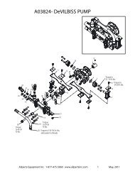
PRODUCTIDENTIFICATIONIgnitor ButtonControl KnobLighting andWarningPlatesASDFKIGLFJI alskdidkoemkgo dkirlnfgpd'fASDFKIGLFJI alskdidkoemkgo dkirlnfgpd'fASDFKIGLFJI alskdidkoemkgo dkirlnfgpd'fASDFKIGLFJI alskdidkoemkgo dkirlnfgpd'fASDFKIGLFJI alskdidkoemkgo dkirlnfgpd'fASDFKIGLFJI alskdidkoemkgo dkirlnfgpd'fASDFKIGLFJI alskdidkoemkgo dkirlnfgpd'fASDFKIGLFJI alskdidkoemkgo dkirlnfgpd'fASDFKIGLFJI alskdidkoemkgo dkirlnfgpd'fASDFKIGLFJI alskdidkoemkgo dkirlnfgpd'fASDFKIGLFJI alskdidkoemkgo dkirlnfgpd'fASDFKIGLFJI alskdidkoemkgo dkirlnfgpd'fASDFKIGLFJI alskdidkoemkgo dkirlnfgpd'fASDFKIGLFJI alskdidkoemkgo dkirlnfgpd'fASDFKIGLFJI alskdidkoemkgo dkirlnfgpd'fASDFKIGLFJI alskdidkoemkgo dkirlnfgpd'fASDFKIGLFJI alskdidkoemkgo dkirlnfgpd'fASDFKIGLFJI alskdidkoemkgo dkirlnfgpd'fASDFKIGLFJI alskdidkoemkgo dkirlnfgpd'fASDFKIGLFJI alskdidkoemkgo dkirlnfgpd'fASDFKIGLFJI alskdidkoemkgo dkirlnfgpd'fASDFKIGLFJI alskdidkoemkgo dkirlnfgpd'fASDFKIGLFJI alskdidkoemkgo dkirlnfgpd'fASDFKIGLFJI alskdidkoemkgo dkirlnfgpd'fASDFKIGLFJI alskdidkoemkgo dkirlnfgpd'ASDFKIGLFJI alskdidkoemkgo dkirlnfgpd'fASDFKIGLFJI alskdidkoemkgo dkirlnfgpd'fASDFKIGLFJI alskdidkoemkgo dkirlnfgpd'fASDFKIGLFJI alskdidkoemkgo dkirlnfgpd'fASDFKIGLFJI alskdidkoemkgo dkirlnfgpd'fASDFKIGLFJI alskdidkoemkgo dkirlnfgpd'fASDFKIGLFJI alskdidkoemkgo dkirlnfgpd'fSDFKIGLFJI alskdidkoemkgo dkirlnfgpd'fASDFKIGLFJI alskdidkoemkgo dkirlnfgpd'fASDFKIGLFJI alskdidkoemkgo dkirlnfgpd'fASDFKIGLFJI alskdidkoemkgo dkirlnfgpd'fASDFKIGLFJI alskdidkoemkgo dkirlnfgpd'fASDFKIGLFJI alskdidkoemkgo dkirlnfgpd'fASDFKIGLFJI alskdidkoemkgo dkirlnfgpd'fASDFKIGLFJI alskdidkoemkgo dkirlnfgpd'fASDFKIGLFJI alskdidkoemkgo dkirlnfgpd'fASDFKIGLFJI alskdidkoemkgo dkirlnfgpd'fASDFKIGLFJI alskdidkoemkgo dkirlnfgpd'ASDFKIGLFJI alskdidkoemkgo dkirlnfgpd'fASDFKIGLFJI alskdidkoemkgo dkirlnfgpd'fASDFKIGLFJI alskdidkoemkgo dkirlnfgpd'fASDFKIGLFJI alskdidkoemkgo dkirlnfgpd'ASDFKIGLFJI alskdidkoemkgo dkirlnfgpd'fASDFKIGLFJI alskdidkoemkgo dkirlnfgpd'fASDFKIGLFJI alskdidkoemkgo dkirlnfgpd'fASDFKIGLFJI alskdidkoemkgo dkirlnfgpd'fASDFKIGLFJI alskdidkoemkgo dkirlnfgpd'fASDFKIGLFJI alskdidkoemkgo dkirlnfgpd'fASDFKIGLFJI alskdidkoemkgo dkirlnfgpd'fASDFKIGLFJI alskdidkoemkgo dkirlnfgpd'fASDFKIGLFJI alskdidkoemkgo dkirlnfgpd'fASDFKIGLFJI alskdidkoemkgo dkirlnfgpd'fASDFKIGLFJI alskdidkoemkgo dkirlnfgpd'fASDFKIGLFJI alskdidkoemkgo dkirlnfgpd'fASDFKIGLFJI alskdidkoemkgo dkirlnfgpd'fSDFKIGLFJI alskdidkoemkgo dkirlnfgpd'fASDFKIGLFJI alskdidkoemkgo dkirlnfgpd'fASDFKIGLFJI alskdidkoemkgo dkirlnfgpd'fASDFKIGLFJI alskdidkoemkgo dkirlnfgpd'fASDFKIGLFJI alskdidkoemkgo dkirlnfgpd'ASDFKIGLFJI alskdidkoemkgo dkirlnfgpd'fASDFKIGLFJI alskdidkoemkgo dkirlnfgpd'fASDFKIGLFJI alskdidkoemkgo dkirlnfgpd'fASDFKIGLFJI alskdidkoemkgo dkirlnfgpd'fASDFKIGLFJI alskdidkoemkgo dkirlnfgpd'fASDFKIGLFJI alskdidkoemkgo dkirlnfgpd'fASDFKIGLFJI alskdidkoemkgo dkirlnfgpd'fHeaterCabinetScreenLogFrontPanelFigure 1 - Vent-Free Gas Log Natural Gas Space HeaterLOCAL CODESInstall and use heater with care. Follow all local codes. In the absence of localcodes, use the latest edition of The National Fuel Gas Code ANSI Z223, alsoknown as NFPA 54*.*Available from:American National Standards Institute, Inc.1430 BroadwayNew York, NY 10018National Fire Protection Association, Inc.Batterymarch ParkQuincy, MA 022694PRODUCTFEATURESUNPACKINGSafety DeviceThis heater has a pilot with an Oxygen Depletion Sensor Shutoff System (ODS).The ODS/pilot is a required feature for vent-free room heaters. The ODS/pilot shutsoff the heater if there is not enough fresh air.Piezo Ignition SystemThis heater has a piezo ignitor. This system requires no matches, batteries, or othersources to light heater.Thermostatic Heat ControlThis heater has a thermostat sensing bulb and a control valve. This results in thegreatest heater comfort. This can also result in lower gas bills.1. Remove heater from carton.2. Remove all protective packaging applied to heater for shipment.3. Make sure your heater includes two hardware packets.4. Check heater for any shipping damage. If heater is damaged, promptly informdealer where you bought heater.101047
ASSEMBLYASSEMBLING HEATERTools Required: Phillips screwdriver, 5/16" hex wrench, and slotted screwdriverRemoving Front Panel Of Heater1. Remove two screws near bottom corners of front panel with Phillips screwdriver.2. Pull bottom of front panel forward, then down (see Figure 2) .Figure 2 - Removing Front Panel of HeaterInstalling LogNote: For easier installation, lay heater on its back.1. Remove log from inside top of heater. Discard protective packaging.2. Attach ignitor cable to piezo ignitor (see Figure 3).Piezo IgnitorIgnitor CableFigure 3 - Attaching Ignitor Cable to Piezo Ignitor1010473. With Phillips screwdriver, remove four screws holding screen in place. Removescreen.4. Gently slide log between log retaining brackets on deflector assembly (see Figure4, page 6). The log should fit firmly against bottom of log retaining brackets.5. Reattach screen using four screws removed in step 3.Continued5
ASSEMBLYContinuedWARNING ICON G 001WARNINGAlways have burner shield and screen in place before operatingheater. This prevents excessive temperatures on heater surfaces.LogHeater CabinetDeflectorFront PanelScreenLogRetainingBracketsTruss-HeadScrewNutBurner ShieldScrewBrassFrontTrimScrewFigure 4 - Assembling HeaterAttaching Brass Front Trim to Front Panel1. Locate brass front trim in brass trim package.2. Slide the head of two truss-head screws from hardware packet into each end ofbrass front trim (see Figure 5).3. Line up screws with holes in front panel (see Figure 4). Insert screws in holes.Attach nuts from inside of front panel. Tighten with wrench.Brass FrontTrimFront PanelTruss-Head ScrewNut6Figure 5 - Attaching Brass Front Trim to Front Panel101047
ASSEMBLYContinuedAssembling and Attaching Brass Trim1. Remove packaging from remaining three pieces of brass trim.2. Locate four brass screws, two adjusting plates with set screws, and two shims inthe hardware packet.3. Align shim under adjusting plate as shown in Figure 6.4. Slide one end of adjusting plate/shim in slot on mitered edge of top brass trim(see Figure 6).5. Slide other end of adjusting plate/shim in slot on mitered edge of side brass trim(see Figure 6).6. While firmly holding edges of brass trim together, tighten both set screws on theadjusting plate with slotted screwdriver.Side Brass TrimSet ScrewsTop Brass TrimAdjustingPlateShimSlotScrewsMitered EdgeSlotFigure 6 - Assembling Brass Trim7. Repeat steps 1 through 6 for other side.8. Place the assembled trim on front of heater cabinet. Attach on top and sideswith four brass screws included in hardware package (see Figure 7).AssembledBrass Trim101047Figure 7 - Attaching Brass Trim to Heater9. Reattach front panel to heater if you are going to mount the heater to the base. Donot reattach front panel at this time if you are going to mount heater to wall.7
FRESH AIRFORCOMBUSTIONANDVENTILATIONWARNING ICON G 001WARNINGThis heater must have fresh air for proper operation. If not, poorfuel combustion could result. Read the following instructions toinsure proper fresh air for this and other fuel-burning appliancesin your home.Today’s homes are built more energy efficient than ever. New materials, increasedinsulation, and new construction methods help reduce heat loss in homes. Homeowners weather strip and caulk around windows and doors to keep the cold air outand the warm air in. During heating months, home owners want their homes asairtight as possible.While it is good to make your home energy efficient, your home needs to breathe.Fresh air must enter your home. All fuel-burning appliances need fresh air forproper combustion and ventilation.Exhaust fans, fireplaces, clothes dryers, and fuel burning appliances draw air fromthe house to operate. You must provide adequate fresh air for these appliances.This will insure proper venting of vented fuel-burning appliances.PRODUCING ADEQUATE VENTILATIONAll spaces in homes fall into one of the three following ventilation classifications:1. Unusually Tight Contruction; 2. Unconfined Space; 3. Confined Space.The information on pages 8 through 11 will help you classify your space and provideadequate ventilation.Unusually Tight ConstructionThe air that leaks around doors and windows may provide enough fresh air forcombustion and ventilation. However, in buildings of unusually tight construction,you must provide additional fresh air.Unusually tight construction is defined as construction where:a. walls and ceilings exposed to the outside atmosphere have a continuouswater vapor retarder with a rating of one perm or less with openingsgasketed or sealed andb. weather stripping has been added on openable windows and doors andc. caulking or sealants are applied to areas such as joints around windowand door frames, between sole plates and floors, between wall-ceilingjoints, between wall panels, at penetrations for plumbing, electrical, andgas lines, and at other openings.If your home meets all of the three criteria above, you must provide additionalfresh air. See Ventilation Air From Outdoors, page 11.If your home does not meet all of the three criteria above, continue reading.Unconfined SpaceAn unconfined space has a minimum air volume of 50 cubic feet for each 1000BTU/Hr input rating of all appliances in the space (cubic feet equals length xwidth x height of space). Include adjoining rooms only if there are doorlesspassageways or ventilation grills between the rooms.8Confined SpaceA confined space has an air volume of less than 50 cubic feet for each 1000BTU/Hr input rating of all appliances in the space (cubic feet equals length xwidth x height of space). Include adjoining rooms only if there are doorlesspassageways or ventilation grills between the rooms.101047
FRESH AIRFORCOMBUSTIONANDVENTILATIONContinuedDETERMINING FRESH-AIR FLOW FOR HEATER LOCATIONDetermining if You Have a Confined or Unconfined SpaceUse this worksheet to determine if you have a confined or unconfined space.Space: Includes the room in which you will install heater plus any adjoining rooms withdoorless passageways or ventilation grills between the rooms.1. Determine the volume of the space (length x width x height).Length x Width x Height = ___________________ cu. ft. (volume of space)Example: Space size 20 ft. (length) x 16 ft. (width) x 8 ft. (ceiling height) =2560 cu. ft. (volume of space)If additional ventilation to adjoining room is supplied with grills or openings, add thevolume of these rooms to the total volume of the space.2. Divide the space volume by 50 cubic feet to determine the maximum BTU/Hr the spacecan support.____________ (volume of space) ÷ 50 cu. ft. = (Maximum BTU/Hrthe space can support)Example: 2560 cu. ft. (volume of space) ÷ 50 cu. ft. = 51.2 or 51,200 (maximumBTU/Hr the space can support)3. Add the BTU/Hr of all fuel burning appliances in the space.Vent-free heater ___________________ BTU/HrGas water heater* ___________________ BTU/HrGas furnace___________________ BTU/HrVented gas heater ___________________ BTU/HrGas fireplace logs ___________________ BTU/HrOther gas appliances* + ___________________ BTU/HrTotal= ___________________ BTU/HrExample: Gas water heater 40,000 BTU/HrVent-free heater + 18,000 BTU/HrTotal = 58,000 BTU/Hr* Do not include direct-vent gas appliances. Direct-vent draws combustion air from theoutdoors and vents to the outdoors.4. Compare the maximum BTU/Hr the space can support with the actual amount of BTU/Hr used._________________ BTU/Hr (maximum the space can support)_________________ BTU/Hr (actual amount of BTU/Hr used)Example: 51,200 BTU/Hr (maximum the space can support)58,000 BTU/Hr (actual amount of BTU/Hr used)The space in the above example is a confined space because the actual BTU/Hr used ismore than the maximum BTU/Hr the space can support. You must provide additional freshair. Your options are as follows:A. Rework worksheet, adding the space of an adjoining room. If the extra space providesan unconfined space, remove door to adjoining room or add ventilation grills betweenrooms. See Ventilation Air From Inside Building, page 10.B. Vent room directly to the outdoors. See Ventilation Air From Outdoors, page 11.C. Install a lower BTU/Hr heater, if lower BTU/Hr size makes room unconfined.If the actual BTU/Hr used is less than the maximum BTU/Hr the space can support, thespace is an unconfined space. You will need no additional fresh air ventilation.101047WARNING ICON G 001WARNINGYou must provide additional ventilation air in a confined space.Continued9
FRESH AIRFORCOMBUSTIONANDVENTILATIONContinuedVENTILATION AIRVentilation Air From Inside BuildingThis fresh air would come from an adjoining unconfined space. When ventilating to anadjoining unconfined space, you must provide two permanent openings: one within 12" of theceiling and one within 12" of the floor on the wall connecting the two spaces (see options 1 and2, Figure 8). You can also remove door into adjoining room (see option 3, Figure 8).WARNING ICON G 001WARNINGRework worksheet, adding the space of the adjoining unconfinedspace. The combined spaces must have enough fresh air to supply allappliances in both spaces.12"VentilationGrillsinto AdjoiningRoom,Option 1OrRemoveDoor intoAdjoiningRoom,Option 3Ventilation GrillsInto Adjoining Room,Option 212"Figure 8 - Ventilation Air from Inside Building10101047
FRESH AIRFORCOMBUSTIONANDVENTILATIONContinuedVENTILATION AIR (Continued)Ventilation Air From OutdoorsProvide extra fresh air by using ventilation grills or ducts. You must provide two permanentopenings: one within 12" of the ceiling and one within 12" of the floor. Connect theseitems directly to the outdoors or spaces open to the outdoors. These spaces include atticsand crawl spaces. Follow the National Fuel Gas Code NFPA 54/ANSI Z223.1, Section 5.3,Air for Combustion and Ventilation for required size of ventilation grills or ducts.IMPORTANT: Do not provide openings for inlet or outlet air into attic if attic has a thermostat-controlledpower vent. Heated air entering the attic will activate the power vent.OutletAirVentilatedAtticOutletAirTo AtticInletAirInlet AirVentilatedCrawl SpaceToCrawlSpaceFigure 9 - Ventilation Air from Outdoors10104711
INSTALLATIONNOTICEA qualified service person must install heater. Follow all local codes.CHECK GAS TYPEUse only natural gas. If your gas supply is not natural gas, do not install heater. Calldealer where you bought heater for proper type heater.INSTALLATION ITEMSBefore installing heater, make sure you have the items listed below.• piping (check local codes)• sealant (resistant to propane gas)• manual shutoff valve *• ground joint union• test gauge connection *(see Figure 24, page 21)• sediment trap• tee joint• pipe wrench* An A.G.A. design-certified manual shutoff valve with 1/8" NPT tap is an acceptablealternative to test gauge connection. Purchase the optional A.G.A. design-certifiedmanual shutoff valve from your dealer. See <strong>Accessories</strong>, page 34.LOCATING HEATERWARNING ICON G 001WARNINGMaintain the minimum clearances shown in Figure 10 (page 13). Ifyou can, provide greater clearances from floor, ceiling, and joiningwall.You can locate heater on floor. The optional hearth base is needed. You can alsoinstall the optional decorative mantel on the heater when using the optional hearthbase. IMPORTANT: Only use optional mantel and hearth base specified in thismanual. Purchase the optional mantel and hearth base from your dealer. See<strong>Accessories</strong>, pages 34 and 35.The heater may also be mounted on a wall. You cannot use optional mantel ifmounting heater on a wall.WARNING ICON G 001WARNINGNever install the heater• in a bedroom or bathroom• in a recreational vehicle• where curtains, furniture, clothing, or other flammable objects areless than 36 inches from the front, top, or sides of the heater• as a fireplace insert• in high traffic areas• in windy or drafty areasWARNING ICON G 001CAUTIONThis heater creates warm air currents. These currents move heatto wall surfaces next to heater. Installing heater next to vinyl orcloth wall coverings or operating heater where impurities in the air(such as tobacco smoke) exist, may discolor walls.12IMPORTANT: Vent-free heaters add moisture to the air. Although this is beneficial, installingheater in rooms without enough ventilation air may cause mildew to form fromtoo much moisture. See Fresh Air for Combustion and Ventilation, pages 8 through 11.101047
INSTALLATIONContinuedWARNING ICON G 001CAUTIONIf you install the heater in a home garage• heater pilot and burner must be at least 18 inches above floor.• locate heater where moving vehicle will not hit it.For convenience and efficiency, install heater• where there is easy access for operation, inspection, and service.• in coldest part of room.An optional fan kit is available from your dealer. See <strong>Accessories</strong>, page 34. Ifplanning to use fan, locate heater near an electrical outlet.CEILING6"MinimumFromSides OfHeater36"MinimumLeftSideRightSide5" Minimum To Top SurfaceOf Carpeting, Tile Or OtherFLOORCombustible MaterialFigure 10 - Mounting Clearances As Viewed From Front of HeaterTHERMOSTAT SENSING BULBThe thermostat sensing bulb has been placed inside the heater for protection duringshipping.Locating Thermostat Sensing Bulb1. Remove front panel of heater (see Figure 2, page 5).2. Locate thermostat sensing bulb just under burner assembly.IMPORTANT: Attach thermostat sensing bulb to back of heater for proper operation.Attaching Thermostat Sensing Bulb1. Remove thermostat sensing bulb from holders inside heater. Route through slotopening in bottom of heater.2. Place clamp on thermostat sensing bulb as shown in Figure 11. Clamp is providedin hardware package.3. Snap clamp into upper mounting hole as shown in Figure 11. Mounting hole islocated on lower left edge on back of heater. Make sure the thermostat sensingbulb is pointing up.ThermostatSensing BulbClamp101047Figure 11 - Attaching Thermostat Sensing BulbContinued13
INSTALLATIONContinuedINSTALLATION OPTIONSThere are three options for mounting this heater.A. Mounting heater to wallB. Mounting heater to optional hearth baseC. Mounting heater with optional hearth base to optional mantel.A. MOUNTING HEATER TO WALLMounting BracketThe mounting bracket is located on back panel of heater. It has been taped there forshipping. Remove mounting bracket from back panel.MountingBracketFigure 12 - Mounting Bracket LocationMethods For Attaching Mounting Bracket To WallOnly use last hole on each end of mounting bracket to attach bracket to wall. Thesetwo holes are 16 inches apart from their centers. Attach mounting bracket to wall inone of two ways.1. Attaching to wall stud2. Attaching to wall anchorAttaching to wall stud This method provides the strongest hold. Insert mountingscrews through mounting bracket and into wall studs.Attaching to wall anchor This method allows you to attach mounting bracket tohollow walls (wall areas between studs) or to solid walls (concrete or masonry).Decide which method better suits your needs. Either method will provide a securehold for the mounting bracket.Marking Screw Locations1. Tape mounting bracket to wall where heater will be located. Make sure mountingbracket is level.WARNING ICON G 001WARNINGMaintain minimum clearances shown in Figure 13. If you can,provide greater clearances from floor and joining wall.2. Mark screw locations on wall (see Figure 13).Note: Only mark last hole on each end of mounting bracket. Insert mountingscrews through these holes only.3. Remove tape and mounting bracket from wall.11"Min.16"Adjoining WallOnly Insert MountingScrews Through LastHole On Each End20 3/4"Min.Floor14Figure 13 - Mounting Bracket Clearances101047
INSTALLATIONContinuedAttaching Mounting Bracket To WallNote: Wall anchors, mounting screws, and spacers are in hardware package. Thehardware package is provided with heater.Attaching to wall stud methodFor attaching mounting bracket to wall studs1. Drill holes at marked locations using 9/64" drill bit.2. Place mounting bracket onto wall. Line up last hole on each end of bracket withholes drilled in wall.3. Insert mounting screws through bracket and into wall studs.4. Tighten screws until mounting bracket is firmly fastened to wall studs.Attaching to wall anchor methodFor attaching mounting bracket to hollow walls (wall areas between studs) or solidwalls (concrete or masonry)1. Drill holes at marked locations using 5/16" drill bit. For solid walls (concrete ormasonry), drill at least 1" deep.2. Fold wall anchor as shown in Figure 14.Figure 14 - Folding Anchor3. Insert wall anchor (wings first) into hole. Tap anchor flush to wall.4. For thin walls (1/2" or less), insert red key into wall anchor. Push red key to“pop” open anchor wings. IMPORTANT: Do not hammer key!For thick walls (over 1/2" thick) or solid walls, do not pop open wings.Figure 15 - Popping Open Anchor Wings For Thin Walls5. Place mounting bracket onto wall. Line up last hole on each end of bracket withwall anchors.6. Insert mounting screws through bracket and into wall anchors.7. Tighten screws until mounting bracket is firmly fastened to wall.Placing Heater On Mounting Bracket1. Locate two horizontal slots on back panel of heater.2. Place heater onto mounting bracket. Slide horizontal slots onto stand-out tabs onmounting bracket.Horizontal SlotsStand-Out TabMounting Bracket(attached to wall)101047Figure 16 - Mounting Heater Onto Mounting BracketContinued15
INSTALLATIONContinuedInstalling Bottom Mounting Screws1. Locate two bottom mounting holes. These holes are near bottom on back panelof heater (see Figure 17).2. Mark screw locations on wall.3. Remove heater from mounting bracket.4. If installing bottom mounting screws into hollow or solid wall, install wall anchors.Follow steps 1 through 4 under Attaching To Wall Anchor Method, page 15.If installing bottom mounting screw into wall stud, drill holes at marked locationsusing 9/64" drill bit.5. Replace heater onto mounting bracket.6. Place spacers between bottom mounting holes and wall anchor or drilled hole.7. Hold spacer in place with one hand. With other hand, insert mounting screwthrough bottom mounting hole and spacer. Place tip of screw in opening of wallanchor or drilled hole.8. Tighten both screws until heater is firmly secured to wall. Do not over tighten.Note: Do not replace front panel at this time. Replace front panel after makinggas connections and checking for leaks (see pages 20-23).Figure 17 - Installing Bottom Mounting Screws16B. MOUNTING HEATER ON OPTIONAL HEARTH BASETools needed: #2 Phillips screwdriver, slotted screwdriver, and electric drill (ifsecuring base to floor)The optional hearth base kit includes the following:Hearth Base 4 Wood Screws 4 Sheet Metal Screws Brass Base TrimHearth Insert 4 Anchors Laminate Sheet 2 Brass ScrewsNote: If securing hearth base to floor, follow instructions under Securing HearthBase to Floor, below. If not securing hearth base to floor, proceed to MountingHeater to Hearth Base, page 17.Securing Hearth Base to Floor1. Position hearth base in desired location. Mark holes for drilling (See Figure 18,page 17). Remove hearth base.2. For carpeted floor, make a small cut with a sharp knife at marked locationsbefore drilling.If securing to a wood floor, drill a 3/4" deep hole using a 1/8" diameter drill bit.Do not use anchors in wood floors.If securing to a concrete floor, drill a 1 3/8" deep hole using a 1/4" diameterconcrete drill bit. Completely insert anchors into each hole.3. Mount heater to hearth base following steps under Mounting Heater to HearthBase, page 17. After mounting heater, position heater and hearth base overdrilled holes. With slotted screwdriver, secure hearth base to floor with fourwood screws.101047
INSTALLATIONContinuedMounting Heater to Optional Hearth Base1. Lay heater on its back on a table with the bottom of heater overhanging the edgeof the table.2. Remove 2 shipping screws in bottom of heater. Discard shipping screws.3. Line up mounting holes on top of hearth base with holes in bottom of heater (seeFigure 18).4. Using a Phillips screwdriver, secure hearth base to heater with four sheet metalscrews (see Figure 18).BaseBottom of HeaterShippingScrewMounting HolesHoles for SecuringHeater to FloorSheet MetalScrewFigure 18 - Attaching Heater to Hearth Base5. Stand heater up on base.6. Slide laminate sheet into hearth insert. Place hearth insert on front of hearth baseas shown in Figure 19 below.7. Assemble brass trim (see steps 1 through 7 under Assembling and AttachingBrass Trim, page 7).8. Slide base trim on heater base. Attach brass trim to base with two brass screwsincluded as shown in Figure 19 below.LaminateSheetHearthInsertScrew101047Figure 19 - Placing Hearth Insert on Heater Baseand Attaching Brass Base TrimBrass BaseTrimContinued17
INSTALLATIONContinuedC. MOUNTING HEATER WITH OPTIONAL HEARTH BASE TO OPTIONALMANTEL (The following instructions are for GMF800(A)/GMU801(A) modelsonly. For other mantels, see instructions included with mantel kit.)Assembling MantelIMPORTANT: Only use the optional mantels specified in this manual. See <strong>Accessories</strong>,page 34 for proper mantel kits. This heater is only approved for use withmodels GMF800(A)/GMU801(A), GM900F/GM901U, and GM700F/GM701Umantel kits. Using any other mantel will void the A.G.A. approval for this heater.Only use models GMF800(A)/GMU801(A), GM900F/GM901U, and GM700F/GM701U mantels with this heater. Do not use models GMF800(A)/GMU801(A),GM900F/GM901U, and GM700F/GM701U mantels with any other product.Before installing mantel to heater, the heater must be mounted on the optionalhearth base.Tools needed: #2 Phillips screw driver, electric drill, and 1/8" drill bit.The optional mantel kit contains the following:Right Side Rear Brace 12 Wood ScrewsLeft Side Mantel Front 2 Screws (2")Top (with sliding access panel)2 Wood PlugsFollow the illustrated steps in Figures 20 and 21 below to assemble the mantel.Assemble mantel upside down. The illustrations below are viewed from the rear ofthe mantel. After assembling mantel, see page 19 for instructions to attach mantelto heater.Left SideRight SideMantelFrontFigure 20RearBrace18TopFigure 21101047
INSTALLATIONContinuedInstalling Mantel to HeaterBefore installing mantel to heater, the heater must be mounted on the optionalhearth base. See Mounting Heater on Optional Hearth Base, page 17. Follow thesteps below to install mantel to heater.1. Place mantel over heater (see Figure 22). Back side of mantel should be evenwith back of hearth base. Mantel front should not extend past brass trim aroundheater cabinet.2. Locate pre-drilled holes at bottom of each side of mantel (see Figure 23). Usean electric drill with 1/8" drill bit. Insert drill bit into pre-drilled holes in manteland drill through heater hearth base. Make sure the drill bit does not damageany gas plumbing lines inside hearth base.3. Locate two 2" screws from hardware package. Insert screws through pre-drilledholes at bottom of each side of mantel (see Figure 23). Tighten each screw intothe heater hearth base. Make sure the screw tips do not damage any gas plumbinglines inside hearth base. Note: The pre-drilled holes are countersunk.Tighten the screws all the way into the holes.4. Locate two wood plugs from hardware package. Insert plugs into screw holes(see Figure 23). Tap into place.Pre-DrilledHoleFigure 222" ScrewWood PlugHearth BaseAccessory101047Figure 2319
CONNECTINGTO GASSUPPLYNOTICEA qualified service person must connect heater to gas supply.Follow all local codes.WARNING ICON G 001WARNINGNever connect heater to private (non-utility) gas wells. This gas iscommonly known as well-head gas.IMPORTANT: Check gas line pressure before connecting heater to gas line. Gas linepressure must be no greater than 14 inches of water. If gas line pressure is higher,heater regulator damage could occur.WARNING ICON G 001CAUTIONUse only new, black iron or steel pipe. Internally-tinned coppertubing may be used in certain areas. Check your local codes. Usepipe of 1/2" or greater diameter to allow proper gas volume toheater. If pipe is too small, undue loss of pressure will occur.Installation must include a manual shutoff valve, union, and plugged 1/8" NPT tap.Locate NPT tap within reach for test gauge hook up. NPT tap must be upstreamfrom heater (see Figure 24, page 21).Apply pipe joint sealant lightly to male threads. This will prevent excess sealantfrom going into pipe. Excess sealant in pipe could result in clogged heater valves.WARNING ICON G 001CAUTIONUse pipe joint sealant that is resistant to liquid petroleum (LP) gas.Install sediment trap in supply line as shown in Figure 24, page 21. Locate sedimenttrap where it is within reach for cleaning. Locate sediment trap where trappedmatter is not likely to freeze. A sediment trap traps moisture and contaminants. Thiskeeps them from going into heater controls. If sediment trap is not installed or isinstalled wrong, heater may not run properly.20101047
CONNECTINGTO GASSUPPLYContinuedIMPORTANT: Hold pressure regulator with wrench when connecting it to gas pipingand/or fittings.PressureRegulatorNote: Burner bracketnot shown for clarity1/2" NPTPipe NippleTestGaugeConnection *SedimentTrapTee JointReducerBushing to1/8" NPT1/8" NPTPlug TapTee JointPipeNippleCapGroundUnionJoint3" MinimumFigure 24 - Gas ConnectionHeaterCabinet<strong>Manual</strong> Shutoff Valve *From Gas Meter(4" W.C. to 10.5" W.C. Pressure)* An A.G.A. design-certified manual shutoff valve with 1/8" NPT tap is an acceptablealternative to test gauge connection. Purchase the optional A.G.A. designcertifiedmanual shutoff valve from your dealer. See <strong>Accessories</strong>, page 34.CHECKINGGASCONNECTIONSWARNING ICON G 001WARNINGTest all gas piping and connections for leaks after installing orservicing. Correct all leaks at once.WARNING ICON G 001WARNINGNever use an open flame to check for a leak. Apply a mixture ofliquid soap and water to all joints. Bubbles forming show a leak.Correct all leaks at once.101047PRESSURE TESTING GAS SUPPLY PIPING SYSTEMTest Pressures In Excess Of 1/2 PSIG1. Disconnect heater and its individual manual shutoff valve from gas supplypiping system. Pressures in excess of 1/2 psig will damage heater regulator.2. Cap off open end of gas pipe where manual shutoff valve was connected.Continued21
CHECKINGGASCONNECTIONSContinued3. Pressurize supply piping system by either using compressed air oropening main gas valve located on or near gas meter.4. Check all joints of gas supply piping system. Apply mixture of liquid soap andwater to gas joints. Bubbles forming show a leak.5. Correct all leaks at once.Test Pressures Equal To or Less Than 1/2 PSIG1. Close manual shutoff valve (see Figure 25).2. Pressurize supply piping system by either using compressed air or opening maingas valve located on or near gas meter.3. Check all joints from gas meter to manual shutoff valve (see Figure 25). Applymixture of liquid soap and water to gas joints. Bubbles forming show a leak.4. Correct all leaks at once.PRESSURE TESTING HEATER GAS CONNECTIONS1. Open manual shutoff valve (see Figure 25).2. Open main gas valve located on or near gas meter.3. Make sure control knob of heater is in the OFF position.4. Check all joints from manual shutoff valve to thermostat gas valve (see Figure25). Apply mixture of liquid soap and water to gas joints. Bubbles formingshow a leak.5. Correct all leaks at once.6. Light heater (see Operating Heater, pages 23 through 25). Check all otherinternal joints for leaks.7. Turn off heater (see To Turn Off Gas to Appliance, page 25).8. Replace front panel.OpenONPOSITION<strong>Manual</strong>ShutoffValveOFFPOSITIONClosedFigure 25 - <strong>Manual</strong> Shutoff ValveThermostat Gas Valve LocationGas Meter<strong>Manual</strong>ShutoffValve22Figure 26 - Checking Gas Joints101047
PILOTOFFHIOPERATINGHEATERFOR YOUR SAFETY READ BEFORE LIGHTINGWARNING ICON G 001WARNINGIf you do not follow these instructions exactly, a fire or explosionmay result causing property damage, personal injury orloss of life.A. This appliance has a pilot which must be lighted by hand. When lightingthe pilot, follow these instructions exactly.B. BEFORE LIGHTING smell all around the appliance area for gas. Be sureto smell next to the floor because some gas is heavier than air and willsettle on the floor.WHAT TO DO IF YOU SMELL GAS• Do not try to light any appliance.• Do not touch any electric switch; do not use any phone in your building.• Immediately call your gas supplier from a neighbor’s phone. Followthe gas supplier’s instructions.• If you cannot reach your gas supplier, call the fire department.C. Use only your hand to push in or turn the gas control knob. Never usetools. If the knob will not push in or turn by hand, don’t try to repair it,call a qualified service technician or gas supplier. Force or attemptedrepair may result in a fire or explosion.D. Do not use this appliance if any part has been under water. Immediatelycall a qualified service technician to inspect the appliance and to replaceany part of the control system and any gas control which has been underwater.LIGHTING INSTRUCTIONS1. STOP! Read the safety information above.2. Make sure manual shutoff valve is fully open.3. Turn control knob clockwise Clockwise to the OFF position.Ignitor ButtonControl KnobLOIGNITOR101047Control Figure Knob 27 -& Control Ignitor Button Knob In The GRH/OV OFF 015 PositionContinued23
OPERATINGHEATERContinued4. Wait five (5) minutes to clear out any gas. Then smell for gas, includingnear the floor. If you smell gas, STOP! Follow “B” in the safety informationat the top of page 23. If you don’t smell gas, go to the next step.5. Turn control knob counterclockwise C-clockwise to the PILOT position. Pressin control knob for five (5) seconds (see Figure 27, page 23).Note: You may be running this heater for the first time after hooking upto gas supply. If so, the control knob may need to be pressed in for 30seconds. This will allow air to bleed from the gas system.• If control knob does not pop up when released, contact a qualifiedservice person or gas supplier for repairs.6. With control knob pressed in, push down and release ignitor button. Thiswill light pilot. The pilot is attached to the front of burner. If needed, keeppressing ignitor button until pilot lights.Note: If pilot does not stay lit, refer to Troubleshooting, pages 28 through31. Also contact a qualified service person or gas supplier for repairs.Until repairs are made, light pilot with match. To light pilot with match,see <strong>Manual</strong> Lighting Procedure, page 25.7. Keep control knob pressed in for 30 seconds after lighting pilot. After 30seconds, release control knob.Ignitor ElectrodeThermocouplePilot BurnerFigure 28 - PilotNote: If pilot goes out, repeat steps 3 through 7. This heater has a safetyinterlock system. Wait one (1) minute before lighting pilot again.8. Turn control knob counterclockwise C-clockwise to desired heating level. Themain burner should light. Set control knob to any heat level between HIand LO.WARNING ICON G 001CAUTIONDo not try to adjust heating levels by using the manual shutoff valve.24101047
OPERATINGHEATERContinuedTO TURN OFF GAS TO APPLIANCEShutting Off Heater1. Turn control knob clockwise Clockwise to the OFF position.2. Turn off all electric power to the appliance if service is to be performed.Shutting Off Burner Only (pilot stays lit)1. Turn control knob clockwise Clockwise to the PILOT position.THERMOSTAT CONTROL OPERATIONThe thermostatic control used on this heater differs from standard thermostats.Standard thermostats simply turn on and off the burner. The thermostatused on this heater senses the room temperature. The thermostat adjusts theamount of gas flow to the burner. This increases or decreases the burner flameheight. At times the room may exceed the set temperature. If so, the burnerwill shut off. The burner will cycle back on when room temperature dropsbelow the set temperature.The control knob can be set to any heat level between HI and LO.Note: The thermostat sensing bulb measures the temperature of air near theheater cabinet. This may not always agree with room temperature (dependingon housing construction, installation location, room size, open air temperatures,etc.). Frequent use of your heater will let you determine your owncomfort levels.MANUAL LIGHTING PROCEDURE1. Remove front panel (see Figure 2, page 5).2. Follow steps 1 through 5 under Lighting Instructions, pages 23 and 24.3. With control knob pressed in, strike match. Hold match to pilot until pilotlights.4. Keep control knob pressed in for 30 seconds after lighting pilot. After 30seconds, release control knob.5. Replace front panel.10104725
INSPECTINGBURNERCheck pilot flame pattern and burner flame pattern often.PILOT FLAME PATTERNFigure 29 shows a correct pilot flame pattern. Figure 30 shows an incorrect pilotflame pattern. The incorrect pilot flame is not touching the thermocouple. This willcause the thermocouple to cool. When the thermocouple cools, the heater will shutdown.ThermocouplePilot BurnerGood Figure Pilot-Nat. 29 - Correct Port Pilot GRH/OV Flame 007D PatternThermocouplePilot BurnerBad Pilot-Nat. Port GRH/OV 007EFigure 30 - Incorrect Pilot Flame PatternIf pilot flame pattern is incorrect, as shown in Figure 30• turn heater off (see To Turn Off Gas to Appliance, page 25).• see Troubleshooting, pages 28 through 31.26101047
INSPECTINGBURNERContinuedBURNER FLAME PATTERNFigure 31 shows a correct burner flame pattern. Figure 32 shows an incorrectburner flame pattern. The incorrect burner flame pattern shows yellow tipping ofthe flame. It also shows the flame higher than one inch above the log.Note: When using the heater the first time, the flame will be yellow for approximatelyone hour until the log cures.WARNING ICON G 001WARNINGIf yellow tipping occurs, your heater could produce increasedlevels of carbon monoxide. If burner flame pattern shows yellowtipping, follow instructions at bottom of this page.NOTICEDo not mistake orange flames with yellow tipping. Dirt or other fineparticles enter the heater and burn causing brief patches of orangeflame.Top ofFlameAbout OneInch AboveLogsCORRECT FLAME PATTERNAT HIGH POSITIONFigure 31 - Correct Burner Flame PatternYellowTippingINCORRECT FLAME PATTERNAT HIGH POSITIONFigure 32 - Incorrect Burner Flame PatternIf burner flame pattern is incorrect, as shown in Figure 32• turn heater off (see To Turn Off Gas to Appliance, page 25).• see Troubleshooting, pages 28 through 31.10104727
CLEANINGANDMAINTENANCEWARNING ICON G 001WARNINGTurn off heater and let cool before cleaning.WARNING ICON G 001CAUTIONYou must keep control areas, burner, and circulating air passagewaysof heater clean. Inspect these areas of heater before eachuse. Have heater inspected yearly by a qualified service person.Heater may need more frequent cleaning due to excessive lint fromcarpeting, bedding material, etc.ODS/PILOT AND BURNER• Use a vacuum cleaner, pressurized air, or small, soft bristled brush to clean.CABINETAir Passageways• Use a vacuum cleaner or pressurized air to clean.Exterior• Use a soft cloth dampened with a mild soap and water mixture. Wipe thecabinet to remove dust.TROUBLE-SHOOTINGNote: All troubleshootingitems are listed in order ofoperation.WARNING ICON G 001WARNINGTurn off and unplug heater and let cool before servicing. Only aqualified service person should service and repair heater.WARNING ICON G 001CAUTIONNever use a wire, needle, or similar object to clean ODS/pilot. Thiscan damage ODS/pilot unit.OBSERVEDPROBLEMPOSSIBLECAUSEREMEDY28When ignitor buttonis pressed, there is nospark at ODS/pilot1. Ignitor electrode positionedwrong2. Ignitor electrode broken3. Ignitor electrode not connectedto ignitor cable4. Ignitor cable pinched orwet5. Piezo ignitor nut is loose6. Broken ignitor cable7. Bad piezo ignitor1. Replace ignitor2. Replace ignitor3. Reconnect ignitor cable4. Free ignitor cable ifpinched by any metal ortubing. Keep ignitorcable dry5. Tighten nut holdingpiezo ignitor to heatercabinet. Nut is locatedinside heater cabinet attop6. Replace ignitor cable7. Replace piezo ignitor101047
TROUBLE-SHOOTINGContinuedOBSERVEDPROBLEMWhen ignitor buttonis pressed, there isspark at ODS/pilotbut no ignitionPOSSIBLECAUSE1. Gas supply turned offor manual shutoffvalve closed2. Control knob not inPILOT position3. Control knob notpressed in while inPILOT position4. Air in gas lines wheninstalled5. ODS/pilot is clogged6. Gas regulator setting isnot correctREMEDY1. Turn on gas supply oropen manual shutoffvalve2. Turn control knob toPILOT position3. Press in control knobwhile in PILOTposition4. Continue holdingdown control knob.Repeat igniting operationuntil air is removed5. Clean ODS/pilot (seeCleaning and Maintenance,page 28) orreplace ODS/pilotassembly6. Replace gas regulatorODS/pilot lights butflame goes out whencontrol knob isreleased1. Control knob not fullypressed in2. Control knob notpressed in long enough3. Safety interlock systemhas been triggered4. <strong>Manual</strong> shutoff valvenot fully open5. Thermocouple connectionloose at controlvalve6. Pilot flame not touchingthermocouple,which allows thermocoupleto cool, causingpilot flame to go out.This problem could becaused by one or bothof the following:A) Low gas pressureB) Dirty or partiallyclogged ODS/pilot7. Thermocouple damaged8. Control valve damaged1. Press in control knobfully2. After ODS/pilot lights,keep control knobpressed in 30 seconds3. Wait one minute forsafety interlock systemto reset. Repeatignition operation4. Fully open manualshut-off valve5. Hand tighten untilsnug, then tighten 1/4turn more6. A) Contact localnatural gas companyB) Clean ODS/pilot(see Cleaning andMaintenance, page 28)or replace ODS/pilotassembly7. Replace thermocouple8. Replace control valve101047Continued29
TROUBLE-SHOOTINGContinuedOBSERVEDPROBLEMBurner does not lightafter ODS/pilot is litPOSSIBLECAUSE1. Burner orifice isclogged2. Burner orifice diameteris too small3. Inlet gas pressure istoo lowREMEDY1. Clean burner (seeCleaning and Maintenance,page 28) orreplace burner orifice2. Replace burner orifice3. Contact local natural gascompanyDelayed ignition ofburner1. Manifold pressure istoo low2. Burner orifice isclogged1. Contact local natural gascompany2. Clean burner (seeCleaning and Maintenance,page 28) orreplace burner orificeBurner backfiringduring combustion1. Burner orifice isclogged or damaged2. Burner damaged3. Gas regulator defective1. Clean burner (seeCleaning and Maintenance,page 28) orreplace burner orifice2. Replace burner3. Replace gas regulatorYellow flame duringburner combustion1. Not enough air2. Gas regulator defective1. Check burner for dirtand debris. If found,clean burner (seeCleaning and Maintenance,page 28)2. Replace gas regulatorSlight smoke or odorduring initial operation1. Residues from manufacturingprocesses1. Problem will stop after afew hours of operation30Heater produces awhistling noise whenburner is lit1. Turning control knobto HI position whenburner is cold2. Air in gas line3. Air passageways onheater blocked4. Dirty or partiallyclogged burner orifice1. Turn control knob to LOposition and let warm upfor a minute2. Operate burner until airis removed from line.Have gas line checkedby local natural gascompany3. Observe minimuminstallation clearances(see Figure 10, page 13)4. Clean burner (seeCleaning and Maintenance,page 28) orreplace burner orifice101047
TROUBLE-SHOOTINGContinuedWARNING ICON G 001WARNINGIf you smell gas• Shut off gas supply.• Do not try to light any appliance.• Do not touch any electrical switch; do not use anyphone in your building.• Immediately call your gas supplier from a neighbor’sphone. Follow the gas supplier’s instructions.• If you cannot reach your gas supplier, call the firedepartment.IMPORTANT: Operating heater where impurities in air exist may create odors.Cleaning supplies, paint, paint remover, cigarette smoke, cements and glues, newcarpet or textiles, etc., create fumes. These fumes may mix with combustion air andcreate odors.OBSERVEDPROBLEMPOSSIBLECAUSEREMEDYHeater produces aclicking/ticking noisejust after burner is litor shut off1. Metal expanding whileheating or contractingwhile cooling1. This is common withmost heaters. If noise isexcessive, contactqualified service personHeater producesunwanted odors1. Heater burning vaporsfrom paint, hair spray,glues, etc. (see IMPOR-TANT statement above)2. Gas leak. See Warningstatement attop of page1. Ventilate room. Stopusing odor causingproducts while heater isrunning2. Locate and correct allleaks (see Checking GasConnections, page 21)Heater shuts off inuse (ODS operates)1. Not enough fresh air isavailable2. Low line pressure3. ODS/pilot is partiallyclogged1. Open window and/ordoor for ventilation2. Contact local natural gascompany3. Clean ODS/pilot (seeCleaning and Maintenance,page 28)Gas odor even whencontrol knob is inOFF position1. Gas leak. See Warningstatement attop of page2. Control valve defective1. Locate and correct allleaks (see Checking GasConnections, page 21)2. Replace control valve101047Gas odor duringcombustion1. Foreign matter betweencontrol valveand burner2. Gas leak. See Warningstatement attop of page1. Take apart gas tubingand remove foreignmatter2. Locate and correct allleaks (see Checking GasConnections,page 21)31
TECHNICALSERVICESPECIFICATIONSSERVICEHINTSYou may have further questions about installation, operation, or troubleshooting.If so, contact DESA International’s Technical Service Department at 1-800-323-5190.BTU (Variable) 14,000/28,000Type GasNatural OnlyIgnitionPiezoPressure Regulator Setting3" W.C.Inlet Gas Pressure (in. of water) *Maximum 10.5"Minimum 5"Dimensions, Inches (H x W x D)Heater 23.5 x 25.9 x 8.0Carton 25.8 x 28.7 x 10.1Weight (pounds)Heater 30Shipping 35* For purposes of input adjustmentWhen gas pressure is too low• pilot will not stay lit• burner will have delayed ignition• heater will not produce specified heatWhen gas quality is bad• pilot will not stay lit• burner will produce flames and soot• heater will backfire when litYou may feel your gas pressure is too low or gas quality is bad. If so, contact yourlocal natural gas supplier.REPLACEMENTPARTS32Note: Use only original replacement parts. This will protect your warranty coveragefor parts replaced under warranty.Parts Under WarrantyContact authorized dealers of this product. If they can’t supply original replacementpart(s), either contact your nearest Parts Central (see page 33) or call DESAInternational’s Technical Service Department at 1-800-323-5190.When calling DESA International, have ready• your name• your address• model number of your heater• how heater was malfunctioning• type of gas used (propane or natural gas)• purchase dateUsually, we will ask you to return the defective part to the factory.Parts Not Under WarrantyContact authorized dealers of this product. If they can’t supply original replacementpart(s), either contact your nearest Parts Central (see page 33) or call DESAInternational’s Parts Department at 1-800-972-7879 for information.When calling DESA International, have ready• model number of your heater• the replacement part number101047
PARTSCENTRALSThese Parts Centrals are privately owned businesses. They have agreed to supportour customer’s needs by providing original replacement parts and accessories.Portable Heater Parts342 N. County Rd. 400 EastValparaiso, IN 46383All States219-462-74411-800-362-6951Master Service Center1184 Wilson NWWalker, MI 49504616-791-47601-800-446-1446Halco Enterprises208 Carter Drive, Unit 21West Chester, PA 19382215-696-26701-800-368-0803Cans Unlimited, Inc.P.O. Box 645Taylor, SC 29687All States803-879-30091-800-845-5301Washer <strong>Equipment</strong> Co.1715 Main StreetKansas City, MO 64108KS, MO, AR816-842-3911Dealers LPP.O. Box 341145Bartlett, TN 38184AL, TN901-386-8780East Coast Energy Products833 BroadwayW. Long Branch, NJ 07764908-870-88091-800-755-8809Tarantin Tank Co.P.O. Box 6129Freehold, NJ 07728908-780-93401-800-922-072410104733
ACCESSORIESPurchase these heater accessories from your local dealer. If they can not supplythese accessories, either contact your nearest Parts Central (see page 33) or callDESA International’s Sales Department at 1-800-458-2472 for information. Youcan also write to the address listed on the back page of this manual.MANUAL SHUTOFF VALVE - GA5010<strong>Manual</strong> shutoff valve with 1/8" NPT tap.FAN KIT - GA3100 (GA2100A)Provides better heat distribution. Makes heater moreefficient. Complete installation and operating instructionsincluded.HEARTH BASE - GHB802AFor locating heater on the floor. Includes brasstrim and reversible black metal / sandstonelaminate filler. Complete installation instructionsincluded.GS601 - Black SurroundFor locating heater in front of anexisting fireplace. The sturdy steelconstruction is accented with decorativebrass trim. Complete installationinstructions included.34101047
ACCESSORIESSTANDARD MANTELUnfinished - GMU801(A)Finished - GMF800(A)For use with heater and hearth base. Areal oak mantel offers compact stylingand completes the fireplace look.Available in finished oak or unfinishedoak, ready to stain or paint.Complete assembly and installationinstructions included.PREMIER MANTELUnfinished - GM901UFinished - GM900FFor use with heater and hearthbase. Sturdy hardwood constructionembellished with flutedsides, raised medallions, andcarved rope trim. Available in awalnut finish or an unfinishedhardwood, ready to stain or paint.Complete assembly and installationinstructions included.CORNER MANTELUnfinished - GM701UFinished - GM700FFor use with heater and hearthbase. Space-saving corner designfeaturing clean, classic lines.Available in a walnut finish or anunfinished hardwood, ready tostain or paint. Complete assemblyand installation instructionsincluded.10104735
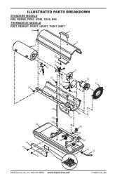
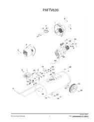
132530291910411121131814261522161923172725242021628107812-112-236101047
PARTS LISTThis list contains replaceable parts used in your heater. When ordering parts, followthe instructions listed under Replacement Parts on page 32 of this manual.KEY PARTNO. NUMBER DESCRIPTION QTY.1 098304-01 Screw, #10 x 3/8" 62 100566-01CB Front Panel 13 100573-01BR Screen Assembly 14 100721-01BR Burner Shield 15 100903-02 Log 16 M11084-38 Screw, #8 x 3/8" 27 099066-01 Mounting Bracket 18 M11084-26 Screw, #10 x 3/8" 49 100571-01BR Deflector Unit 110 098271-03 Ignitor Cable 111 098249-01 Nut, M5 212 099440-05 ODS/Pilot Assembly 112-1 098593-01 Thermocouple 112-2 098594-01 Ignitor Electrode 113 099126-02 Burner 114 098517-01 3/16" Pilot Tubing 115 098251-04 Injector 116 098250-01 Injector Holder 117 098867-04 Pressure Regulator 118 099553-01 Pilot Shield 119 098299-02 3/8" Outlet (Burner) Tubing 120 098297-03 3/8" Inlet Tubing 121 098264-02 3/8" NPT Male Connector 122 098276-01 1/8" NPT Plug 123 098277-01 3/8" to 1/8" NPT Bushing 124 098265-01 3/8" NPT Male Elbow 125 098275-01 3/8" NPT Plug 126 098522-04 Thermostat Gas Valve 127 098529-03 Cabinet 128 097159-02 Piezo Ignitor 129 098304-03 Screw, #8 x 3/8" 430 101046-01 Log Strap 2PARTS AVAILABLE — NOT SHOWN100565-01 Bead Chain 1100562-01 Lighting Instructions Plate 1100563-01 Warning Plate 1100586-01 Brass Trim Assembly 1100587-01 Brass Plated Trim Screw 4100642-01 Hardware Package (Includes SetScrews and Adjusting Plates) 1100687-01 Truss-Head Screw 4NPC-1C Hex Nut for Truss-Head Screw 410104737
38NOTES_______________________________________________________________________________________________________________________________________________________________________________________________________________________________________________________________________________________________________________________________________________________________________________________________________________________________________________________________________________________________________________________________________________________________________________________________________________________________________________________________________________________________________________________________________________________________________________________________________________________________________________________________________________________________________________________________________________________________________________________________________________________________________________________________________________________________________________________________________________________________________________________________________________________________________________________________________________________________________________________________________________________________________________________________________________________________________________________________________________________________________________________________________________________________________________________________________________________________________________________________________________________________________________________________________________________________________________________________________________________________________________________________________________________________________________________________________________________________________________________________________________________________________________________________________________________________________________________________________________________________________________________________________________________________________________________________________________________________________________________________________________________________________________________________________________________________________________________________________________________________________________________________________________________________________________________________________________________________________101047
101047NOTES_______________________________________________________________________________________________________________________________________________________________________________________________________________________________________________________________________________________________________________________________________________________________________________________________________________________________________________________________________________________________________________________________________________________________________________________________________________________________________________________________________________________________________________________________________________________________________________________________________________________________________________________________________________________________________________________________________________________________________________________________________________________________________________________________________________________________________________________________________________________________________________________________________________________________________________________________________________________________________________________________________________________________________________________________________________________________________________________________________________________________________________________________________________________________________________________________________________________________________________________________________________________________________________________________________________________________________________________________________________________________________________________________________________________________________________________________________________________________________________________________________________________________________________________________________________________________________________________________________________________________________________________________________________________________________________________________________________________________________________________________________________________________________________________________________________________________________________________________________________________________________________________________________________________________________________________________________________________________________39
WARRANTY INFORMATIONKEEP THIS WARRANTYModelSerial No.Date PurchasedAlways specify model and serial numbers when communicating with the factory.We reserve the right to amend these specifications at any time without notice. The only warranty applicable is ourstandard written warranty. We make no other warranty, expressed or implied.LIMITED WARRANTYVENT-FREE GAS LOG NATURAL GAS SPACE HEATERSDESA International warrants this product to be free from defects in materials and components for two (2) years fromthe date of first purchase, provided that the product has been properly installed, operated and maintained inaccordance with all applicable instructions. To make a claim under this warranty the Bill of Sale or cancelled checkmust be presented.This warranty is extended only to the original retail purchaser. This warranty covers the cost of part(s) required torestore this heater to proper operating condition and an allowance for labor when provided by a DESA AuthorizedService Center. Warranty part(s) MUST be obtained through authorized dealers of this product and/or DESAInternational who will provide original factory replacement parts. Failure to use original factory replacement partsvoids this warranty. The heater MUST be installed by a qualified installer in accordance with all local codes andinstructions furnished with the unit.This warranty does not apply to parts that are not in original condition because of normal wear and tear, or parts thatfail or become damaged as a result of misuse, accidents, lack of proper maintenance or defects caused by improperinstallation. Travel, diagnostic cost, labor, transportation and any and all such other costs related to repairing adefective heater will be the responsibility of the owner.TO THE FULL EXTENT ALLOWED BY THE LAW OF THE JURISDICTION THAT GOVERNS THE SALEOF THE PRODUCT; THIS EXPRESS WARRANTY EXCLUDES ANY AND ALL OTHER EXPRESSEDWARRANTIES AND LIMITS THE DURATION OF ANY AND ALL IMPLIED WARRANTIES, INCLUDINGWARRANTIES OF MERCHANTABILITY AND FITNESS FOR A PARTICULAR PURPOSE TO TWO (2)YEARS FROM THE DATE OF FIRST PURCHASE; AND DESA INTERNATIONAL’S LIABILITY IS HEREBYLIMITED TO THE PURCHASE PRICE OF THE PRODUCT AND DESA INTERNATIONAL SHALL NOT BELIABLE FOR ANY OTHER DAMAGES WHATSOEVER INCLUDING INDIRECT, INCIDENTAL OR CON-SEQUENTIAL DAMAGES.Some states do not allow a limitation on how long an implied warranty lasts or an exclusion or limitation of incidentalor consequential damages, so the above limitation on implied warranties, or exclusion or limitation on damages maynot apply to you.This warranty gives you specific legal rights, and you may also have other rights that vary from state to state.For information about this warranty write:2701 Industrial DriveP.O. Box 90004Bowling Green, KY 42102-9004101047-01REV. D5/94