dsPIC33F FRM Section 39. Oscillator (Part III)
dsPIC33F FRM Section 39. Oscillator (Part III)
dsPIC33F FRM Section 39. Oscillator (Part III)

You also want an ePaper? Increase the reach of your titles
YUMPU automatically turns print PDFs into web optimized ePapers that Google loves.
<strong>Section</strong> <strong>39.</strong> <strong>Oscillator</strong> (<strong>Part</strong> <strong>III</strong>)HIGHLIGHTSThis section of the manual contains the following topics:<strong>39.</strong>1 Introduction .................................................................................................................. 39-2<strong>39.</strong>2 CPU Clocking...............................................................................................................39-3<strong>39.</strong>3 <strong>Oscillator</strong> Configuration Registers ............................................................................... 39-4<strong>39.</strong>4 Special Function Registers .......................................................................................... 39-7<strong>39.</strong>5 Primary <strong>Oscillator</strong>....................................................................................................... 39-14<strong>39.</strong>6 Internal Fast RC (FRC) <strong>Oscillator</strong> .............................................................................. 39-18<strong>39.</strong>7 Phase-Locked Loop (PLL) ......................................................................................... 39-19<strong>39.</strong>8 Low-Power Secondary <strong>Oscillator</strong> (SOSC) ................................................................. 39-24<strong>39.</strong>9 Low-Power RC <strong>Oscillator</strong>........................................................................................... 39-25<strong>39.</strong>10 Auxiliary <strong>Oscillator</strong> ..................................................................................................... 39-26<strong>39.</strong>11 Fail-Safe Clock Monitor (FSCM) ................................................................................ 39-27<strong>39.</strong>12 Clock Switching.......................................................................................................... 39-28<strong>39.</strong>13 Two-Speed Start-Up................................................................................................... 39-32<strong>39.</strong>14 Register Maps............................................................................................................ 39-33<strong>39.</strong>15 Related Application Notes.......................................................................................... 39-34<strong>39.</strong>16 Revision History ......................................................................................................... 39-3539<strong>Oscillator</strong> (<strong>Part</strong> <strong>III</strong>)© 2008 Microchip Technology Inc. DS70216B-page 39-1
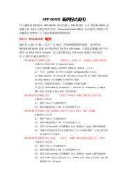
<strong>dsPIC33F</strong> Family Reference Manual<strong>39.</strong>1 INTRODUCTIONThe <strong>dsPIC33F</strong> oscillator system includes these characteristics:• External and internal oscillator options• On-chip PLL to boost internal operating frequency on select internal and external oscillatorsources• On-the-fly clock switching between various clock sources• Doze mode for system power-saving• Fail-Safe Clock Monitor (FSCM) that detects clock failure and permits safe applicationrecovery or shutdown• Nonvolatile Configuration bits for clock source selection• Auxiliary Crystal <strong>Oscillator</strong> for Digital-to-Analog Converter (DAC)A block diagram of the <strong>dsPIC33F</strong> oscillator system is shown in Figure 39-1.Figure 39-1:<strong>Oscillator</strong> (<strong>Part</strong> <strong>III</strong>) System Block DiagramPrimary <strong>Oscillator</strong>DOZEOSCOOSCIPOSCCLKS3POSCMDS1PLLXT, HS, ECXTPLL, HSPLL,ECPLL, FRCPLLFVCO (1)S2S1/S3DOZEFCY÷ 2FRC<strong>Oscillator</strong>FRCDIVFRCDIVNS7FOSCTUN÷16FRCDIVFRCDIV16FRCS6S0LPRC<strong>Oscillator</strong>LPRCS5SOSCOSecondary <strong>Oscillator</strong>SOSCS4LPOSCENSOSCIClock FailClock SwitchResetAuxiliary <strong>Oscillator</strong>POSCCLKAOSCCLKS7FVCO (1)NOSC FNOSC÷N ACLKWDT, PWRT,FSCMTimer1DACAOSCMDASRCSELSELACLKAPSTSCLRNote 1:See <strong>39.</strong>7 “Phase-Locked Loop (PLL)” for FVCO values.DS70216B-page 39-2© 2008 Microchip Technology Inc.
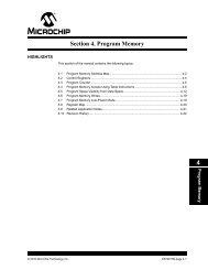
<strong>Section</strong> <strong>39.</strong> <strong>Oscillator</strong> (<strong>Part</strong> <strong>III</strong>)<strong>39.</strong>2 CPU CLOCKINGThe system clock (FOSC) source can be provided by one of the following options:• Primary <strong>Oscillator</strong> (POSC) on the OSCI and OSCO pins• Secondary <strong>Oscillator</strong> (SOSC) on the SOSCI and SOSCO pins• Internal Fast RC <strong>Oscillator</strong> (FRC) with optional clock divider• Internal Low-Power RC <strong>Oscillator</strong> (LPRC)• Primary <strong>Oscillator</strong> with PLL• Internal Fast RC <strong>Oscillator</strong> with PLLThe system clock source is divided by two to produce the internal instruction cycle clock. Theinstruction cycle clock is denoted by FCY. The timing diagram in Figure 39-2 shows therelationship between the system clock (FOSC), the instruction cycle clock (FCY), and the ProgramCounter (PC).The internal instruction cycle clock (FCY) can be output on the OSCO I/O pin, if the Primary<strong>Oscillator</strong> mode or the HS mode is not selected as the clock source (see <strong>39.</strong>5 “Primary<strong>Oscillator</strong>”).Figure 39-2:Clock/Instruction Cycle TimingTCYFOSCFCYPCPCPC + 2 PC + 4Fetch INST (PC)Execute INST (PC - 2) Fetch INST (PC + 2)Execute INST (PC) Fetch INST (PC + 4)Execute INST (PC + 2)39<strong>Oscillator</strong> (<strong>Part</strong> <strong>III</strong>)© 2008 Microchip Technology Inc. DS70216B-page 39-3
<strong>dsPIC33F</strong> Family Reference Manual<strong>39.</strong>3 OSCILLATOR CONFIGURATION REGISTERSTable 39-1 lists the configuration settings that select the device oscillator source and Operatingmode at Power-on Reset (POR). The Configuration bits are contained in these two registers:• FOSCSEL: <strong>Oscillator</strong> Source Selection RegisterThe <strong>Oscillator</strong> Source Selection (FOSCSEL) register selects the initial oscillator source andstart-up option.• FOSC: <strong>Oscillator</strong> Configuration RegisterThe <strong>Oscillator</strong> Configuration (FOSC) register configures the Primary <strong>Oscillator</strong> mode, OSCOpin function, peripheral pin select, and the fail-safe and clock switching modes.The Configuration registers are located in program memory space. They are not Special FunctionRegisters (SFRs). They are mapped into program memory space and are programmed at thetime of device programming.The Initial <strong>Oscillator</strong> Source Selection (FNOSC) Configuration bits in the <strong>Oscillator</strong> SourceSelection (FOSCSEL) register determine the clock source that is used at a Power-onReset. Thereafter, the clock source can be changed between permissible clock sources withclock switching. The Internal FRC oscillator with postscaler (FRCDIVN) is the default(unprogrammed) selection.The Primary <strong>Oscillator</strong> Mode Selection (POSCMD) Configuration bits in the <strong>Oscillator</strong>Configuration (FOSC) register select the Operation mode of the primary oscillator.The OSCO Pin Function bit (OSCIOFNC) Configuration bit in FOSC selects the OSCO pinfunction, except in HS or XT mode. When OSCIOFNC is unprogrammed (‘1’), the FCY clock isoutput on the OSCO pin. When OSCIOFNC is programmed (‘0’), the OSCO pin becomes ageneral purpose I/O pin.Table 39-1:<strong>Oscillator</strong>SourceConfiguration Bit Values for Clock Selection<strong>Oscillator</strong> ModeFNOSCValuePOSCMDValueNoteS0 Fast RC <strong>Oscillator</strong> (FRC) 000 xx 1S1 Fast RC <strong>Oscillator</strong> with PLL (FRCPLL) 001 xx 1S2 Primary <strong>Oscillator</strong> (EC) 010 00 1S2 Primary <strong>Oscillator</strong> (XT) 010 01 —S2 Primary <strong>Oscillator</strong> (HS) 010 10 —S3 Primary <strong>Oscillator</strong> with PLL (ECPLL) 011 00 1S3 Primary <strong>Oscillator</strong> with PLL (XTPLL) 011 01 —S3 Primary <strong>Oscillator</strong> with PLL (HSPLL) 011 10 —S4 Secondary <strong>Oscillator</strong> (SOSC) 100 xx 1S5 Low-Power RC <strong>Oscillator</strong> 101 xx 1S6 Fast RC <strong>Oscillator</strong> with Divide-by-16 (FRCDIV16) 110 xx 1S7 Fast RC <strong>Oscillator</strong> with Divide-by-N (FRCDIVN) 111 xx 1, 2Note 1: The OSCO pin function is determined by the OSCIOFNC Configuration bit.2: The default oscillator mode for an unprogrammed (erased) device.DS70216B-page 39-4© 2008 Microchip Technology Inc.
<strong>Section</strong> <strong>39.</strong> <strong>Oscillator</strong> (<strong>Part</strong> <strong>III</strong>)Register 39-1:FOSCSEL: <strong>Oscillator</strong> Source Selection RegisterU U U U U U U U— — — — — — — —bit 15 bit 8R/P U U U U R/P R/P R/PIESO — — — — FNOSCbit 7 bit 0Legend:R = Readable bit P = Programmable bit U = Unused bits, program to Logic ‘1’-n = Value at POR ‘1’ = Bit is set ‘0’ = Bit is cleared x = Bit is unknownbit 15-8 Reserved: Reserved bits must be programmed as ‘1’bit 7 IESO: Internal External Start-up Option bit1 = Start device with Internal FRC, and then auto-switch to the user-selected oscillator source when ready0 = Start device with user-selected oscillator sourcebit 6-3 Reserved: Reserved bits must be programmed as ‘1’bit 2-0 FNOSC: Initial <strong>Oscillator</strong> Source Selection bits000 = Fast RC <strong>Oscillator</strong> (FRC)001 = Fast RC <strong>Oscillator</strong> with PLL (FRCPLL)010 = Primary <strong>Oscillator</strong> (XT, HS, EC)011 = Primary <strong>Oscillator</strong> with PLL (XTPLL, HSPLL, ECPLL)100 = Secondary <strong>Oscillator</strong> (SOSC)101 = Low-Power RC <strong>Oscillator</strong> (LPRC)110 = Fast RC <strong>Oscillator</strong> with Divide-by-16 (FRCDIV16)111 = Fast RC <strong>Oscillator</strong> with Divide-by-N (FRCDIVN)39<strong>Oscillator</strong> (<strong>Part</strong> <strong>III</strong>)© 2008 Microchip Technology Inc. DS70216B-page 39-5
<strong>dsPIC33F</strong> Family Reference ManualRegister 39-2: FOSC: <strong>Oscillator</strong> Configuration RegisterU U U U U U U U— — — — — — — —bit 15 bit 8R/P R/P R/P U U R/P R/P R/PFCKSM IOL1WAY — — OSCIOFNC POSCMDbit 7 bit 0Legend:R = Readable bit P = Programmable bit U = Unused bits, program to Logic ‘1’-n = Value at POR ‘1’ = Bit is set ‘0’ = Bit is cleared x = Bit is unknownbit 15-8 Reserved: Reserved bits must be programmed as ‘1’bit 7-6 FCKSM: Clock Switching Mode bits1x = Clock switching is disabled, Fail-Safe Clock Monitor is disabled01 = Clock switching is enabled, Fail-Safe Clock Monitor is disabled00 = Clock switching is enabled, Fail-Safe Clock Monitor is enabledbit 5 IOL1WAY: Peripheral Pin Select Configuration bit (1)1 = Allow only one reconfiguration0 = Allow multiple reconfigurationsbit 4-3 Reserved: Reserved bits must be programmed as ‘1’bit 2bit 1-0OSCIOFNC: OSCO Pin Function bit (except in XT and HS modes)1 = OSCO is clock output and instruction cycle (FCY) clock is output on OSCO pin0 = OSCO is a general purpose digital I/O pinPOSCMD: Primary <strong>Oscillator</strong> Mode Selection bits11 = Primary <strong>Oscillator</strong> disabled10 = HS (High-Speed) Crystal <strong>Oscillator</strong> mode01 = XT (Crystal) <strong>Oscillator</strong> mode00 = EC (External Clock) modeNote 1:The IOL1WAY bit is not available on all <strong>dsPIC33F</strong> devices. Refer to the specific device data sheet for moreinformation.DS70216B-page 39-6© 2008 Microchip Technology Inc.
<strong>Section</strong> <strong>39.</strong> <strong>Oscillator</strong> (<strong>Part</strong> <strong>III</strong>)<strong>39.</strong>4 SPECIAL FUNCTION REGISTERSThese Special Function Registers provide run-time control and status of the oscillator system:• OSCCON: <strong>Oscillator</strong> Control RegisterThe <strong>Oscillator</strong> Control (OSCCON) register controls clock switching and provides statusinformation that allows the current clock source, PLL lock, and clock fail conditions to bemonitored.• CLKDIV: Clock Divisor RegisterThe Clock Divisor (CLKDIV) register controls the Doze mode and selects the PLL prescaler,PLL postscaler and FRC postscaler.• PLLFBD: PLL Feedback Divisor RegisterThe PLL Feedback Divisor (PLLFBD) register selects the PLL feedback divisor.• OSCTUN: FRC <strong>Oscillator</strong> Tuning RegisterThe FRC <strong>Oscillator</strong> Tuning (OSCTUN) register is used to tune the Internal FRC <strong>Oscillator</strong>frequency in software. It allows the FRC oscillator frequency to be adjusted over a range of±12%.• ACLKCON: Auxiliary Clock Control RegisterThe Auxiliary Clock Control (ACLKCON) register controls the Auxiliary <strong>Oscillator</strong> mode and theauxiliary output clock divider.Note:The <strong>Oscillator</strong> Special Function Registers (OSCCON, CLKDIV, PLLFBD, OSCTUNand ACLKCON) are reset only on a Power-on Reset.39<strong>Oscillator</strong> (<strong>Part</strong> <strong>III</strong>)© 2008 Microchip Technology Inc. DS70216B-page 39-7
<strong>dsPIC33F</strong> Family Reference ManualRegister 39-3:OSCCON: <strong>Oscillator</strong> Control RegisterU-0 R-y R-y R-y U-0 R/W-y R/W-y R/W-y— COSC — NOSCbit 15 bit 8R/S-0 R/W-0 R-0 U-0 R/C-0 U-0 R/W-0 R/W-0CLKLOCK IOLOCK (1) LOCK — CF — LPOSCEN OSWENbit 7 bit 0Legend: U= Unimplemented bit, read as ‘0’ y = Depends on FOSCSEL bitsR = Readable bit W = Writable bit C = Clearable only bit S = Settable only bit-n = Value at POR ‘1’ = Bit is set ‘0’ = Bit is cleared x = Bit is unknownbit 15 Unimplemented: Read as ‘0’bit 14-12 COSC: Current <strong>Oscillator</strong> Selection bits (read-only)000 = Fast RC <strong>Oscillator</strong> (FRC)001 = Fast RC <strong>Oscillator</strong> with PLL (FRCPLL)010 = Primary <strong>Oscillator</strong> (XT, HS, EC)011 = Primary <strong>Oscillator</strong> with PLL (XTPLL, HSPLL, ECPLL)100 = Secondary <strong>Oscillator</strong> (SOSC)101 = Low-Power RC <strong>Oscillator</strong> (LPRC)110 = Fast RC <strong>Oscillator</strong> with Divide-by-16 (FRCDIV16)111 = Fast RC <strong>Oscillator</strong> with Divide-by-N (FRCDIVN)bit 11 Unimplemented: Read as ‘0’bit 10-8 NOSC: New <strong>Oscillator</strong> Selection bits000 = Fast RC <strong>Oscillator</strong> (FRC)001 = Fast RC <strong>Oscillator</strong> with PLL (FRCPLL)010 = Primary <strong>Oscillator</strong> (XT, HS, EC)011 = Primary <strong>Oscillator</strong> with PLL (XTPLL, HSPLL, ECPLL)100 = Secondary <strong>Oscillator</strong> (SOSC)101 = Low-Power RC <strong>Oscillator</strong> (LPRC)110 = Fast RC <strong>Oscillator</strong> with Divide-by-16 (FRCDIV16)111 = Fast RC <strong>Oscillator</strong> with Divide-by-N (FRCDIVN)bit 7CLKLOCK: Clock Lock Enable bitIf clock switching is enabled and FSCM is disabled (FOSC = 01)1 = Clock switching is disabled, system clock source is locked0 = Clock switching is enabled, system clock source may be modified by clock switchingbit 6 IOLOCK: Peripheral Pin Select Lock bit (1)1 = Peripheral Pin Select is locked. Writes to Peripheral Pin Select registers are not allowed0 = Peripheral Pin Select is not locked. Writes to Peripheral Pin Select registers are allowedbit 5LOCK: PLL Lock Status bit (read-only)1 = Indicates that PLL is in lock, or PLL start-up timer is satisfied0 = Indicates that PLL is out of lock, start-up timer is in progress or PLL is disabledbit 4 Unimplemented: Read as ‘0’bit 3CF: Clock Fail Detect bit (read/clear by application)1 = FSCM has detected clock failure0 = FSCM has not detected clock failurebit 2 Unimplemented: Read as ‘0’Note 1:The IOLOCK bit is not available on all <strong>dsPIC33F</strong> devices. Refer to the specific device data sheet for moreinformation.DS70216B-page 39-8© 2008 Microchip Technology Inc.
<strong>Section</strong> <strong>39.</strong> <strong>Oscillator</strong> (<strong>Part</strong> <strong>III</strong>)Register 39-3:bit 1bit 0OSCCON: <strong>Oscillator</strong> Control Register (Continued)LPOSCEN: Secondary <strong>Oscillator</strong> (SOSC) Enable bit1 = Enable Secondary <strong>Oscillator</strong>0 = Disable Secondary <strong>Oscillator</strong>OSWEN: <strong>Oscillator</strong> Switch Enable bit1 = Request oscillator switch to selection specified by NOSC bits0 = <strong>Oscillator</strong> switch is completeNote 1:The IOLOCK bit is not available on all <strong>dsPIC33F</strong> devices. Refer to the specific device data sheet for moreinformation.39<strong>Oscillator</strong> (<strong>Part</strong> <strong>III</strong>)© 2008 Microchip Technology Inc. DS70216B-page 39-9
<strong>dsPIC33F</strong> Family Reference ManualRegister 39-4:CLKDIV: Clock Divisor RegisterR/W-0 R/W-0 R/W-1 R/W-1 R/W-0 R/W-0 R/W-0 R/W-0ROI DOZE DOZEN (1) FRCDIVbit 15 bit 8R/W-0 R/W-1 U-0 R/W-0 R/W-0 R/W-0 R/W-0 R/W-0PLLPOST — PLLPREbit 7 bit 0Legend:R = Readable bit W = Writable bit U = Unimplemented bit, read as ‘0’-n = Value at POR ‘1’ = Bit is set ‘0’ = Bit is cleared x = Bit is unknownbit 15ROI: Recover on Interrupt bit1 = Interrupts will clear the DOZEN bit and the processor clock/peripheral clock ratio is set to 1:10 = Interrupts have no effect on the DOZEN bitbit 14-12 DOZE: Processor Clock Reduction Select bits000 = FCY/1001 = FCY/2010 = FCY/4011 = FCY/8 (default)100 = FCY/16101 = FCY/32110 = FCY/64111 = FCY/128bit 11 DOZEN: DOZE Mode Enable bit (1)bit 10-81 = DOZE field specifies the ratio between the peripheral clocks and the processor clocks0 = Processor clock/peripheral clock ratio forced to 1:1FRCDIV: Internal Fast RC <strong>Oscillator</strong> Postscaler bits000 = FRC/1 (default)001 = FRC/2010 = FRC/4011 = FRC/8100 = FRC/16101 = FRC/32110 = FRC/64111 = FRC/256bit 7-6 PLLPOST: PLL VCO Output Divider Select bits (also denoted as ‘N2’, PLL postscaler)00 = Output/201 = Output/4 (default)10 = Reserved11 = Output/8bit 5 Unimplemented: Read as ‘0’bit 4-0PLLPRE: PLL Phase Detector Input Divider Select bits (also denoted as ‘N1’, PLL prescaler)00000 = Input/2 (default)00001 = Input/3•••11111 = Input/33Note 1:This bit is cleared when the ROI bit is set and an interrupt occurs.DS70216B-page 39-10© 2008 Microchip Technology Inc.
<strong>Section</strong> <strong>39.</strong> <strong>Oscillator</strong> (<strong>Part</strong> <strong>III</strong>)Register 39-5:PLLFBD: PLL Feedback Divisor RegisterU-0 U-0 U-0 U-0 U-0 U-0 U-0 R/W-0— — — — — — — PLLDIVbit 15 bit 8R/W-0 R/W-0 R/W-1 R/W-1 R/W-0 R/W-0 R/W-0 R/W-0PLLDIVbit 7 bit 0Legend:R = Readable bit W = Writable bit U = Unimplemented bit, read as ‘0’-n = Value at POR ‘1’ = Bit is set ‘0’ = Bit is cleared x = Bit is unknownbit 15-9 Unimplemented: Read as ‘0’bit 8-0 PLLDIV: PLL Feedback Divisor bits (also denoted as ‘M’, PLL multiplier)000000000 = 2000000001 = 3000000010 = 4•••000110000 = 50 (default)•••111111111 = 51339<strong>Oscillator</strong> (<strong>Part</strong> <strong>III</strong>)© 2008 Microchip Technology Inc. DS70216B-page 39-11
<strong>dsPIC33F</strong> Family Reference ManualRegister 39-6:OSCTUN: FRC <strong>Oscillator</strong> Tuning RegisterU-0 U-0 U-0 U-0 U-0 U-0 U-0 U-0— — — — — — — —bit 15 bit 8U-0 U-0 R/W-0 R/W-0 R/W-0 R/W-0 R/W-0 R/W-0— — TUNbit 7 bit 0Legend:R = Readable bit W = Writable bit U = Unimplemented bit, read as ‘0’-n = Value at POR ‘1’ = Bit is set ‘0’ = Bit is cleared x = Bit is unknownbit 15-6 Unimplemented: Read as ‘0’bit 5-0 TUN: FRC <strong>Oscillator</strong> Tuning bits011111 = Center frequency + 11.625% (8.23 MHz)011110 = Center frequency + 11.25% (8.20 MHz)•••000001 = Center frequency + 0.375% (7.40 MHz)000000 = Center frequency (7.37 MHz nominal)111111 = Center frequency - 0.375% (7.345 MHz)•••100001 = Center frequency - 11.625% (6.52 MHz)100000 = Center frequency - 12% (6.49 MHz)DS70216B-page 39-12© 2008 Microchip Technology Inc.
<strong>Section</strong> <strong>39.</strong> <strong>Oscillator</strong> (<strong>Part</strong> <strong>III</strong>)Register 39-7:ACLKCON: Auxiliary Clock Control RegisterU-0 U-0 R/W-0 R/W-0 R/W-0 R/W-0 R/W-0 R/W-0— — SELACLK AOSCMD APSTSCLRbit 15 bit 8R/W-0 U-0 U-0 U-0 U-0 U-0 U-0 U-0ASRCSEL — — — — — — —bit 7 bit 0Legend:R = Readable bit W = Writable bit U = Unimplemented bit, read as ‘0’-n = Value at POR ‘1’ = Bit is set ‘0’ = Bit is cleared x = Bit is unknownbit 15-14 Unimplemented: Read as ‘0’bit 13 SELACLK: Select Auxiliary Clock Source for Auxiliary Clock Divider1 = Auxiliary <strong>Oscillator</strong> provides the source clock for Auxiliary Clock Divider0 = Fast RC (FRC) with PLL provides the source clock for Auxiliary Clock Dividerbit 12-11 AOSCMD: Auxiliary <strong>Oscillator</strong> Mode11 = EC (External Clock) Mode Select10 = XT (Crystal) <strong>Oscillator</strong> Mode Select01 = HS (High-Speed) <strong>Oscillator</strong> Mode Select00 = Auxiliary <strong>Oscillator</strong> Disabled (default)bit 10-8 APSTSCLR: Auxiliary Clock Output Divider111 = Divided by 1110 = Divided by 2101 = Divided by 4100 = Divided by 8011 = Divided by 16010 = Divided by 32001 = Divided by 64000 = Divided by 256 (default)bit 7ASRCSEL: Select Reference Clock Source for Auxiliary Clock1 = Primary <strong>Oscillator</strong> is the Clock Source0 = Auxiliary <strong>Oscillator</strong> is the Clock Sourcebit 6-0 Unimplemented: Read as ‘0’39<strong>Oscillator</strong> (<strong>Part</strong> <strong>III</strong>)© 2008 Microchip Technology Inc. DS70216B-page 39-13
<strong>dsPIC33F</strong> Family Reference Manual<strong>39.</strong>5 PRIMARY OSCILLATORThe Primary <strong>Oscillator</strong> is available on the OSCI and OSCO pins of the <strong>dsPIC33F</strong> device family.This connection enables an external crystal (or ceramic resonator) to provide the clock to thedevice. Optionally, the internal PLL can be used to boost the system frequency (FOSC) to 80 MHzfor 40 MIPS execution. The Primary <strong>Oscillator</strong> provides the following modes of operation:• Crystal <strong>Oscillator</strong> (XT Mode)The XT mode is a medium-gain, medium-frequency mode used to work with crystalfrequencies of 3 MHz to 10 MHz.• High-Speed <strong>Oscillator</strong> (HS Mode)The HS mode is a high-gain, high-frequency mode used to work with crystal frequencies of10 MHz to 40 MHz.• External Clock Source Operation (EC Mode)If the on-chip oscillator is not used, the EC mode allows the Internal <strong>Oscillator</strong> to be bypassed.The device clocks are generated from an external source (0.8 MHz to 64 MHz) and input onthe OSCI pin.The Initial <strong>Oscillator</strong> Source Selection (FNOSC) Configuration bits in the <strong>Oscillator</strong> SourceSelection (FOSCSEL) register specify the primary oscillator clock source at Power-onReset. The Primary <strong>Oscillator</strong> Mode Selection (POSCMD) Configuration bits in the<strong>Oscillator</strong> Configuration (FOSC) register specify the Primary <strong>Oscillator</strong> mode. Table 39-2shows the options selected by specific bit configurations, which are programmed at the time ofdevice programming.Table 39-2:Primary <strong>Oscillator</strong> Clock Source OptionsFNOSCValuePOSCMDPrimary <strong>Oscillator</strong> Source/Mode011 00 Primary <strong>Oscillator</strong> with PLL: External Clock Mode (ECPLL)011 01 Primary <strong>Oscillator</strong> with PLL: Crystal <strong>Oscillator</strong> with PLL Mode (XTPLL)011 10 Primary <strong>Oscillator</strong> with PLL: High-Speed <strong>Oscillator</strong> with PLL Mode(HSPLL)010 00 Primary <strong>Oscillator</strong>: External Clock Mode (EC)010 01 Primary <strong>Oscillator</strong>: Crystal <strong>Oscillator</strong> Mode (XT)010 10 Primary <strong>Oscillator</strong>: High-Speed Mode (HS)Figure 39-3 shows a recommended crystal oscillator circuit diagram for <strong>dsPIC33F</strong> devices.Capacitors C1 and C2 form the load capacitance for the crystal. The optimum load capacitance(CL) for a given crystal is specified by the crystal manufacturer. Load capacitance can becalculated as shown in Equation 39-1.Figure 39-3:Crystal or Ceramic Resonator Operation (XT or HS <strong>Oscillator</strong> Mode)<strong>dsPIC33F</strong>OSCIC1To Internal LogicXTALPOSCMDC2OSCODS70216B-page 39-14© 2008 Microchip Technology Inc.
<strong>Section</strong> <strong>39.</strong> <strong>Oscillator</strong> (<strong>Part</strong> <strong>III</strong>)Equation 39-1:Crystal Load Capacitancewhere:C S is the stray capacitanceC1 ⋅ C2C L= C + SC1-------------------- + C2Assuming C1 = C2, Equation 39-2 gives the capacitor value (C1, C2) for a given load and straycapacitance.Equation 39-2:External Capacitor for CrystalC1 = C2 = 2 ⋅ ( C L– C S)For additional information on crystal oscillators and their operation, refer to <strong>39.</strong>15 “RelatedApplication Notes”.<strong>39.</strong>5.1 <strong>Oscillator</strong> Start-up TimeThe oscillator starts oscillating as the device voltage increases from VSS. The time required forthe oscillator to start oscillating depends on the following factors:• Crystal/Resonator frequency• Capacitor values used (C1 and C2 in Figure 39-3)• Device VDD rise time• System temperature• Series resistor value and type if used• <strong>Oscillator</strong> mode selection of device (selects the gain of the internal oscillator inverter)• Crystal quality• <strong>Oscillator</strong> circuit layout• System noiseFigure 39-4 shows a graph of a typical oscillator/resonator start-up.Figure 39-4:Example <strong>Oscillator</strong>/Resonator Start-up CharacteristicsMaximum VDD of SystemDevice VDD39VIHVoltageVIL0VCrystal Start-up TimeTime<strong>Oscillator</strong> (<strong>Part</strong> <strong>III</strong>)To ensure that a crystal oscillator (or ceramic resonator) has started and stabilized, an <strong>Oscillator</strong>Start-up Timer (OST) is provided with the Primary <strong>Oscillator</strong> (POSC) and the Secondary<strong>Oscillator</strong> (SOSC). The OST is a simple 10-bit counter that counts 1024 cycles before releasingthe oscillator clock to the rest of the system. This time-out period is denoted as TOST.The amplitude of the oscillator signal must reach the VIL and VIH thresholds for the oscillator pinsbefore the OST can begin to count cycles. The TOST interval is required every time the oscillatorrestarts (i.e., on POR, BOR and wake-up from Sleep mode).© 2008 Microchip Technology Inc. DS70216B-page 39-15
<strong>dsPIC33F</strong> Family Reference ManualOnce the Primary <strong>Oscillator</strong> is enabled, it takes a finite amount of time to start oscillating. Thisdelay is denoted as TOSCD. After TOSCD, the OST timer takes 1024 clock cycles (TOST) to releasethe clock. The total delay for the clock to be ready is TOSCD + TOST. If the PLL is used, anadditional delay is required for the PLL to lock (see <strong>39.</strong>7 “Phase-Locked Loop (PLL)”).Primary <strong>Oscillator</strong> start-up characteristics are illustrated in Figure 39-5, where the CPU startstoggling an I/O pin when it starts execution after the TOSCD + TOST interval.Figure 39-5:<strong>Oscillator</strong> Start-up CharacteristicsTable 39-3:<strong>Oscillator</strong> Source<strong>39.</strong>5.2 Primary <strong>Oscillator</strong> Pin FunctionalityThe Primary <strong>Oscillator</strong> pins (OSCI/OSCO) can be used for other functions when the oscillator isnot being used.The POSCMD Configuration bits in the <strong>Oscillator</strong> Configuration (FOSC) register determinethe <strong>Oscillator</strong> pin function.The OSCIOFNC bit (FOSC) determines the OSCO pin function. When FOSC is ‘0’,OSCO is a general purpose digital I/O pin (see Figure 39-6). When FOSC is ‘1’, OSCO is aclock output, and the instruction cycle (FCY) clock is output on the OSCO pin (see Figure 39-7).The <strong>Oscillator</strong> pin functions are shown in Table 39-3.Clock Pin Function SelectionOSCIOFNCValuePOSCMDValueOSCI (1)Pin FunctionOSCO (2)Pin FunctionPrimary OSC Disabled 1 11 Digital I/O Clock Output (FCY)Primary OSC Disabled 0 11 Digital I/O Digital I/OHS (High-Speed) X 10 OSCI OSCOXT (Crystal) X 01 OSCI OSCOEC (External Clock) 1 00 OSCI Clock Output (FCY)EC (External Clock) 0 00 OSCI Digital I/ONote 1: OSCI pin function is determined by Primary <strong>Oscillator</strong> Mode (POSCMD) Configuration bits.2: OSCI pin function is determined by Primary <strong>Oscillator</strong> Mode (POSCMD) and OSCO Pin Function(OSCIOFNC) Configuration bits.DS70216B-page 39-16© 2008 Microchip Technology Inc.
<strong>Section</strong> <strong>39.</strong> <strong>Oscillator</strong> (<strong>Part</strong> <strong>III</strong>)Figure 39-6: OSCO Pin for Digital I/O (in EC Mode), FOSC = 0Clock from ExternalSystemOSCI<strong>dsPIC33F</strong>I/OOSCOFigure 39-7: OSCO Pin for Clock Output (in EC Mode), FOSC = 1Clock from ExternalSystemOSCI<strong>dsPIC33F</strong>FCYOSCO39<strong>Oscillator</strong> (<strong>Part</strong> <strong>III</strong>)© 2008 Microchip Technology Inc. DS70216B-page 39-17
<strong>dsPIC33F</strong> Family Reference Manual<strong>39.</strong>6 INTERNAL FAST RC (FRC) OSCILLATORThe Internal Fast RC (FRC) <strong>Oscillator</strong> provides a nominal 7.37 MHz clock without requiring anexternal crystal or ceramic resonator, which results in system cost savings for applications thatdo not require a precise clock reference.The application software can tune the frequency of the oscillator from -12% to +11.625% (30 kHzsteps) of the nominal frequency value using the FRC <strong>Oscillator</strong> Tuning (TUN) bits in theFRC <strong>Oscillator</strong> Tuning (OSCTUN) register. The nominal or tuned frequency of the FRC<strong>Oscillator</strong> is expected to remain within ± 2% of the tuned value over temperature and voltagevariations of a particular device.Note:Refer to the specific device data sheet for the accuracy of FRC clock frequency overtemperature and voltage variations.The Internal FRC <strong>Oscillator</strong> starts up instantly. Unlike a crystal oscillator, which can take severalmilliseconds to begin oscillation, the Internal FRC starts oscillating immediately.The Initial <strong>Oscillator</strong> Source Selection (FNOSC) Configuration bits in the <strong>Oscillator</strong> SourceSelection (FOSCSEL) register select the FRC clock source. The FRC Clock Sourceoptions at the time of Power-on Reset are shown in Table 39-4. The Configuration bits areprogrammed at the time of device programming.Table 39-4:FRC Clock Source OptionsFNOSC ValuePrimary <strong>Oscillator</strong> Source/Mode111 FRC <strong>Oscillator</strong>: Postscaler by N (FRCDIVN)110 FRC <strong>Oscillator</strong>: Postscaler by 16 (FRCDIV16)001 FRC <strong>Oscillator</strong> with PLL (FRCPLL)000 FRC <strong>Oscillator</strong> (FRC)<strong>39.</strong>6.1 FRC Postscaler Mode (FRCDIVN)In FRC Postscaler mode, a variable postscaler divides the FRC clock output and allows a lowerfrequency to be chosen. The postscaler is controlled by the Internal Fast RC <strong>Oscillator</strong>Postscaler (FRCDIV) bits in the Clock Divisor (CLKDIV) register. These bits allowfor eight settings, from 1:1 to 1:256, as shown in Figure 39-5.Table 39-5:Internal Fast RC <strong>Oscillator</strong> Postscaler SettingsFRCDIV ValueInternal FRC <strong>Oscillator</strong> Setting111 FRC divide by 256110 FRC divide by 64101 FRC divide by 32100 FRC divide by 16011 FRC divide by 8010 FRC divide by 4001 FRC divide by 2000 FRC divide by 1 (default)Optionally, the FRC postscaler output can be used with the internal PLL to boost the systemfrequency (FOSC) to 80 MHz for 40 MIPS instruction cycle execution speed.Note:The FRC Divider should not be changed dynamically when operating in InternalFRC with PLL.To change the FRC divider:1. Switch the clock to a non-PLL mode (e.g., Internal FRC).2. Make the necessary changes.3. Switch the clock back to the PLL mode.DS70216B-page 39-18© 2008 Microchip Technology Inc.
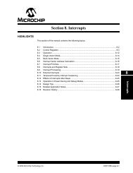
<strong>Section</strong> <strong>39.</strong> <strong>Oscillator</strong> (<strong>Part</strong> <strong>III</strong>)<strong>39.</strong>7 PHASE-LOCKED LOOP (PLL)The Primary <strong>Oscillator</strong> and Internal FRC <strong>Oscillator</strong> sources can also be used with an on-chip PLLto obtain higher operating speeds. A block diagram of the PLL module is shown in Figure 39-8.Figure 39-8:<strong>dsPIC33F</strong> PLL Block Diagram0.8 < FREF < 8.0 MHz100 < FVCO < 200 MHZ FOSC < 80 MHzFIN FREF FVCO FOSC÷ N1PFDVCO÷ N2PLLPRE÷ MPLLPOSTPLLDIVFor proper PLL operation, the Phase Frequency Detector (PFD) input frequency and VoltageControlled <strong>Oscillator</strong> (VCO) output frequency must meet the following requirements:• The PFD input frequency (FREF) must be in the range of 0.8 MHz to 8.0 MHz• The VCO output frequency (FVCO) must be in the range of 100 MHz to 200 MHzThe PLL Phase Detector Input Divider Select (PLLPRE) bits in the Clock Divisor(CLKDIV) register specify the input divider ratio (N1), which is used to scale down the inputclock (FIN) to meet the PFD input frequency range of 0.8 MHz to 8 MHz.The PLL Feedback Divisor (PLLDIV) bits in the PLL Feedback Divisor (PLLFBD)register specify the divider ratio (M), which scales down the VCO frequency (FVCO) for feedbackto the PFD. The VCO frequency (FVCO) is ‘M’ times the input reference clock (FREF).The PLL VCO Output Divider Select (PLLPOST) bits in the Clock Divisor (CLKDIV)register specify the divider ratio (N2) to limit the system clock frequency (FOSC) to 80 MHz.Equation 39-3 gives the relation between the input frequency (FIN) and the output frequency(FOSC).Equation 39-3:FOSCFOSC Calculationwhere:N1 = PLLPRE + 2N2 = 2 x (PLLPOST + 1)M = PLLDIV + 2MFIN ⎛--------------------⎞( PLLDIV + 2)= × = FIN⎝N1× N2⎠× ---------------------------------------------------------------------------------------⎝⎛ ( PLLPRE + 2) × 2( PLLPOST + 1)⎠⎞39<strong>Oscillator</strong> (<strong>Part</strong> <strong>III</strong>)Equation 39-4 gives the relation between the input frequency (FIN) and the VCO frequency(FVCO).Equation 39-4:FVCO CalculationMFVCO FIN ⎛⎝------⎞( PLLDIV + 2)= × FINN1⎠= × ⎝⎛ ------------------------------------( PLLPRE + 2)⎠⎞© 2008 Microchip Technology Inc. DS70216B-page 39-19
<strong>dsPIC33F</strong> Family Reference Manual<strong>39.</strong>7.1 Input Clock Limitation at Start-up for PLL ModeTable 39-6 gives the default values of the PLL Prescaler, PLL Postscaler, and PLL FeedbackDivisor Configuration bits at Power-on Reset.Table 39-6:Given these reset values, the following equations give the relation between the input frequency(FIN) and PFD input frequency (FREF), and the VCO frequency (FVCO) and system clockfrequency (FOSC) at Power-on Reset.Equation 39-5:PLL Mode DefaultsRegister Bit Field Value at POR Reset PLL Divider RatioCLKDIV PLLPRE 00 N1 = 2CLKDIV PLLPOST 01 N2 = 4PLLFBD PLLDIV 000110000 M = 50FREF at Power-on ResetFREF = FIN⎛------1 ⎞ =⎝N1⎠0.5( FIN)Equation 39-6:FVCO at Power-on ResetFVco FIN M ⎝------N1= ⎛ ⎞ = FIN⎛ 50⎠ ⎝----- ⎞ =2 ⎠25( FIN)Equation 39-7:FOSC at Power-on ResetMFOSC = FIN⎛-------------------⎞ = 6.25( FIN)⎝N1 ⋅ N2⎠Given the above equations at Power-on Reset, the input frequency (FIN) to the PLL module mustbe limited to 4 MHz < FIN < 8 MHz to comply with the VCO output frequency requirement(100M < FVCO < 200M), if the default values of PLLPRE, PLLPOST and PLLDIV are used.The Primary <strong>Oscillator</strong> can support the following input frequency ranges, which are not within thefrequency limit required (4 MHz < FIN < 8 MHz) at Power-on Reset:• Primary <strong>Oscillator</strong> in XT mode supports: 3 MHz to 10 MHz crystal• Primary <strong>Oscillator</strong> in HS mode supports: 10 MHz to 40 MHz crystal• Primary <strong>Oscillator</strong> in EC mode supports: 0.8 MHz to 64 MHz inputTo use the PLL when the input frequency is not within the 4 MHz to 8 MHz range, this processmust be followed:1. Power-up the device with Internal FRC or Primary <strong>Oscillator</strong> without PLL.2. Change the PLLDIV, PLLPRE and PLLPOST bit values, based on the input frequency, tomeet these PLL requirements:• The PFD input frequency (FREF) must be in the range of 0.8 MHz to 8.0 MHz• The VCO output frequency (FVCO) must be in the range of 100 MHz to 200 MHz3. Switch the clock to the PLL mode in software.DS70216B-page 39-20© 2008 Microchip Technology Inc.
<strong>Section</strong> <strong>39.</strong> <strong>Oscillator</strong> (<strong>Part</strong> <strong>III</strong>)<strong>39.</strong>7.2 PLL Lock StatusWhenever the PLL input frequency, the PLL prescaler or the PLL feedback divisor is changed,the PLL requires a finite amount of time (TLOCK) to synchronize to the new settings.TLOCK is applied when the PLL is selected as the clock source at Power-on Reset, or during aclock switching operation. The value of TLOCK is relative to the time at which the clock is availableto the PLL input. For example, with the Primary <strong>Oscillator</strong>, TLOCK starts after the OST delay. Referto <strong>39.</strong>5.1 “<strong>Oscillator</strong> Start-up Time” for detailed information.The PLL Lock Status (LOCK) bit in the <strong>Oscillator</strong> Control (OSCCON) register is a read-onlybit that indicates the Lock status of the PLL. The LOCK bit is cleared at Power-on Reset and ona clock-switch operation, when the PLL is selected as the destination clock source. It remainsclear when any clock source not using the PLL is selected. It is a good practice to wait for theLOCK bit to be set before executing code after a clock switch event in which the PLL is enabled.Note:The PLL Prescaler (PLLPRE) and PLL Feedback Divisor (PLLDIV) should not bechanged when operating in PLL mode. You must clock switch to a non-PLL mode(e.g., Internal FRC), to make the necessary changes, and then clock switch back tothe PLL mode.<strong>39.</strong>7.2.1 SETUP FOR USING PLL WITH PRIMARY OSCILLATOR (POSC)The following process can be used to set up the PLL to operate the device at 40 MIPS with a10 MHz external crystal:1. To execute instructions at 40 MHz, ensure that the required system clock frequency is:FOSC = 2 x FCY = 80 MHz2. Ensure that the default reset values of PLLPRE, PLLPOST and PLLDIV meet the PLL anduser requirements.• FREF = 0.5 • FIN = 5 MHz• FOSC = 6.25 • FIN = 62.5 MHz• FVCO = 25 • FIN = 250 MHz• FVCO is not meeting the PLL requirement• FOSC is not meeting the user requirement3. If the PLL and user requirements are met, directly configure the FNOSC bits(FOSCSEL) to select the Primary <strong>Oscillator</strong> with PLL at Power-on Reset. Otherwise,if the PLL and user requirements are not met, follow these steps:a) Select the PLL postscaler to meet the VCO output frequency requirement(100 MHz < FVCO < 200 MHz):- Select a PLL postscaler ratio of N2 = 2- Ensure that Fvco = (Fosc • N2) = 160 MHzb) Select the PLL prescaler to meet the PFD input frequency requirement(0.8 MHz < FREF < 8 MHz):- Select a PLL prescaler ratio of N1 = 2- Ensure that FREF = (FIN/N1) = 5 MHzc) Select the PLL feedback divisor to generate the required VCO output frequencybased on the PFD input frequency:- Fvco = FREF x M- M = Fvco/FREF = 32d) Configure the FNOSC bits (FOSCSEL) to select a clock source without the PLL(e.g., Internal FRC) at Power-on Reset.e) In the main program, change the PLL prescaler, PLL postscaler and PLL feedbackdivisor values to those decided in the previous steps, and then perform a clock switchto the PLL mode.Example 39-1 provides the code for using PLL with the Primary <strong>Oscillator</strong>. See <strong>39.</strong>12 “ClockSwitching” for a clock switching code example.39<strong>Oscillator</strong> (<strong>Part</strong> <strong>III</strong>)© 2008 Microchip Technology Inc. DS70216B-page 39-21
<strong>dsPIC33F</strong> Family Reference ManualExample 39-1: Code Example for Using PLL with Primary <strong>Oscillator</strong> (POSC)// Select Internal FRC at POR_FOSCSEL(FNOSC_FRC);// Enable Clock Switching and Configure POSC in XT mode_FOSC(FCKSM_CSECMD & OSCIOFNC_OFF & POSCMD_XT);int main(){// Configure PLL prescaler, PLL postscaler, PLL divisorPLLFBD=30; // M = 32CLKDIVbits.PLLPOST=0; // N1 = 2CLKDIVbits.PLLPRE=0; // N2 = 2// Initiate Clock Switch to Primary <strong>Oscillator</strong> with PLL (NOSC = 0b011)__builtin_write_OSCCONH(0x03);__builtin_write_OSCCONL(0x01);// Wait for Clock switch to occurwhile (OSCCONbits.COSC != 0b011);// Wait for PLL to lockwhile(OSCCONbits.LOCK!=1) {};}<strong>39.</strong>7.2.2 SETUP FOR USING PLL WITH 7.37 MHz INTERNAL FRCThe following process can be used to set up the PLL to operate the device at 40 MIPS with a7.37 MHz Internal FRC.1. To execute instructions at 40 MHz, ensure that the system clock frequency is:FOSC = 2 x FCY = 80 MHz2. Ensure that the default reset values of PLLPRE, PLLPOST and PLLDIV meet the PLL anduser requirements.• FREF = 0.5 • FIN = 3.68 MHz• FOSC = 6.25 • FIN = 46 MHz• FVCO = 25 • FIN = 184 MHz• FOSC is not meeting the user requirement3. If the PLL and user requirements are met, directly configure the FNOSC bits(FOSCSEL) to select the Primary <strong>Oscillator</strong> with PLL at Power-on Reset. Otherwise,if the PLL and user requirements are not met, follow these steps:a) Select the PLL postscaler to meet the VCO output frequency requirement(100 MHz < FVCO < 200 MHz):- Select a PLL postscaler ratio of N2 = 2- Ensure that FVCO = (FOSC • N2) = 160 MHzb) Select the PLL prescaler to meet the PFD input frequency requirement(0.8 MHz < FREF < 8 MHz):- Select a PLL prescaler ratio of N1 = 2- Ensure that FREF = (Fin/N1) = 3.68 MHzc) Select the PLL feedback divisor to generate the required VCO output frequencybased on the PFD input frequency:- FVCO = FREF x M- M = FVCO/FREF = 43d) Configure the FNOSC bits (FOSCSEL) to select a clock source without PLL(e.g., Internal FRC) at Power-on Reset.e) In the main program, change the PLL prescaler, PLL postscaler, and PLL feedbackdivisor to meet the user and PLL requirement, and then perform a clock switch to thePLL mode.DS70216B-page 39-22© 2008 Microchip Technology Inc.
<strong>Section</strong> <strong>39.</strong> <strong>Oscillator</strong> (<strong>Part</strong> <strong>III</strong>)Example 39-2 provides the code for using PLL with a 7.37 MHz Internal FRC. See <strong>39.</strong>12 “ClockSwitching” for a clock switching code example.Example 39-2:Code Example for Using PLL with 7.37 MHz Internal FRC// Select Internal FRC at POR_FOSCSEL(FNOSC_FRC);// Enable Clock Switching and Configure_FOSC(FCKSM_CSECMD & OSCIOFNC_OFF);int main(){// Configure PLL prescaler, PLL postscaler, PLL divisorPLLFBD = 41; // M = 43CLKDIVbits.PLLPOST=0; // N1 = 2CLKDIVbits.PLLPRE=0; // N2 = 2// Initiate Clock Switch to Internal FRC with PLL (NOSC = 0b001)__builtin_write_OSCCONH(0x01);__builtin_write_OSCCONL(0x01);// Wait for Clock switch to occurwhile (OSCCONbits.COSC != 0b001);// Wait for PLL to lockwhile(OSCCONbits.LOCK!=1) {};}39<strong>Oscillator</strong> (<strong>Part</strong> <strong>III</strong>)© 2008 Microchip Technology Inc. DS70216B-page 39-23
<strong>dsPIC33F</strong> Family Reference Manual<strong>39.</strong>8 LOW-POWER SECONDARY OSCILLATOR (SOSC)The Low-Power Secondary <strong>Oscillator</strong> enables a 32.768 kHz crystal to be attached to the<strong>dsPIC33F</strong> device as a secondary crystal clock source for low-power operation. This oscillatoruses the SOSCI and SOSCO pins. The Low-Power Secondary <strong>Oscillator</strong> can also drive Timer1for real-time clock applications.<strong>39.</strong>8.1 Secondary <strong>Oscillator</strong> for System ClockThe Low-Power Secondary <strong>Oscillator</strong> is enabled as the system clock when:• The Initial <strong>Oscillator</strong> Source Selection (FNOSC) Configuration bits in the <strong>Oscillator</strong>Source Selection (FOSCSEL) register are appropriately set to select the Secondary<strong>Oscillator</strong> at a Power-on Reset• User software initiates a Clock Switch to the Secondary <strong>Oscillator</strong> for low-power operationIf the Low-Power Secondary <strong>Oscillator</strong> is not being used to provide the system clock, or if thedevice enters Sleep mode, it is disabled to save power.<strong>39.</strong>8.2 Secondary <strong>Oscillator</strong> Start-up DelayWhen the Low-Power Secondary <strong>Oscillator</strong> is enabled, it takes a finite amount of time to startoscillating. Refer to <strong>39.</strong>5.1 “<strong>Oscillator</strong> Start-up Time” for details.<strong>39.</strong>8.3 Continuous Secondary <strong>Oscillator</strong> OperationOptionally, you can leave the Secondary <strong>Oscillator</strong> running at all times. The Secondary <strong>Oscillator</strong>is always enabled, if the Secondary <strong>Oscillator</strong> Enable (LPOSCEN) bit is set in the <strong>Oscillator</strong>Control (OSCCON) register.There are two reasons to leave the Low-Power Secondary <strong>Oscillator</strong> running. First, keeping theoscillator on at all times allows a fast switch to the 32 kHz System Clock for lower poweroperation. Returning to the faster main oscillator still requires an oscillator start-up time if it is acrystal type source (see <strong>39.</strong>5.1 “<strong>Oscillator</strong> Start-up Time”). Second, the oscillator shouldremain on at all times when Timer1 is being used as a real-time clock.Note:In Sleep mode, all clock sources (Primary <strong>Oscillator</strong>, Internal FRC and LPRC<strong>Oscillator</strong>) are shut down, with the exception of the Low-Power Secondary<strong>Oscillator</strong>. The Low-Power Secondary <strong>Oscillator</strong> can be active in Sleep mode if theSecondary <strong>Oscillator</strong> Enable (LPOSCEN) bit is set in the <strong>Oscillator</strong> Control(OSCCON) register.DS70216B-page 39-24© 2008 Microchip Technology Inc.
<strong>Section</strong> <strong>39.</strong> <strong>Oscillator</strong> (<strong>Part</strong> <strong>III</strong>)<strong>39.</strong>9 LOW-POWER RC OSCILLATORThe Low-Power RC (LPRC) oscillator provides a nominal clock frequency of 32 kHz. The LPRCis the clock source for the Power-up Timer (PWRT), Watchdog Timer (WDT), and Fail-Safe ClockMonitor (FSCM) circuits. It can also be used to provide a low-frequency clock source option forthe device in those applications where power consumption is critical and timing accuracy is notrequired.Note:The clock frequency of the LPRC oscillator will vary depending on the devicevoltage and operating temperature. Refer to the “Electrical Characteristics” in thespecific device data sheet for details.<strong>39.</strong>9.1 LPRC <strong>Oscillator</strong> for System ClockThe LPRC oscillator is selected as the system clock when:• The Initial <strong>Oscillator</strong> Source Selection (FNOSC) bits in the <strong>Oscillator</strong> SourceSelection (FOSCSEL) register are appropriately set to select the LPRC oscillator atPower-on Reset• User software initiates a Clock Switch to the LPRC oscillator for low-power operation<strong>39.</strong>9.2 Enabling the LPRC <strong>Oscillator</strong>The LPRC oscillator is the clock source for the PWRT, WDT and FSCM.The LPRC oscillator is enabled at Power-on Reset, if the Power-on Reset Timer Value Select(FPWRT) bits in the POR Configuration Fuse (FPOR) register are non-zero.The LPRC oscillator remains enabled under these conditions:• The FSCM is enabled• The WDT is enabled• The LPRC oscillator is selected as the system clockIf none of these conditions is true, the LPRC oscillator shuts off after the PWRT expires. TheLPRC oscillator is shut off in Sleep mode.Note:The LPRC runs in Sleep mode only if the Watchdog Timer is enabled. Under allother conditions, the LPRC is disabled in Sleep mode.<strong>39.</strong>9.3 LPRC <strong>Oscillator</strong> Start-up DelayThe LPRC oscillator starts up instantly, unlike a crystal oscillator, which can take severalmilliseconds to begin oscillation.39<strong>Oscillator</strong> (<strong>Part</strong> <strong>III</strong>)© 2008 Microchip Technology Inc. DS70216B-page 39-25
<strong>dsPIC33F</strong> Family Reference Manual<strong>39.</strong>10 AUXILIARY OSCILLATORThe Auxiliary <strong>Oscillator</strong> (AOSC) can be used for peripherals that need to operate at a frequencyunrelated to the system clock, such as a Digital-to-Analog Converter (DAC). The Auxiliary<strong>Oscillator</strong> can use one of the following as its clock source:• Crystal (XT): Crystal and ceramic resonators in the range of 3 MHz to 10 MHz• High-Speed Crystal (HS): Crystals in the range of 10 MHz to 40 MHz. The external crystalis connected to the SOSCI and SOSCO pins• External Clock (EC): External clock signal up to 64 MHz. The external clock signal isdirectly applied to the SOSCI pin<strong>39.</strong>10.1 Enabling the Auxiliary <strong>Oscillator</strong>To enable the Auxiliary <strong>Oscillator</strong> mode and External <strong>Oscillator</strong> mode, the appropriate Auxiliary<strong>Oscillator</strong> Mode (AOSCMD) bits must be selected in the Auxiliary Clock Control(ACLKCON) register. These bits allow for four oscillator mode settings, as shown inTable 39-7. Once the mode has been selected, set the Select Auxiliary Clock Source for AuxiliaryClock Divider (SELACLK) bit (ACLKCON) to use the Auxiliary <strong>Oscillator</strong> as the clockreference.Table 39-7:Auxiliary <strong>Oscillator</strong> and External <strong>Oscillator</strong> Mode SettingsAOSCMD Bit Value<strong>Oscillator</strong> Mode Setting11 EC (External Clock) Mode Select10 XT (Crystal) <strong>Oscillator</strong> Mode Select01 HS (High-Speed) <strong>Oscillator</strong> Mode Select00 Auxiliary <strong>Oscillator</strong> Disabled (default setting)Note:By default, the DAC module is clocked by the FRC with PLL. To use the Primary<strong>Oscillator</strong> as the clock source, set the following bits in the ACLKCON register:• ASRCSEL (selects primary oscillator for the reference clock)• SELACLK (enables the reference clock)<strong>39.</strong>10.2 Auxiliary Clock Output DividerThe Auxiliary Clock Output Divider (APSTSCLR) bits in the ACLKCON registerdivide the auxiliary clock, which allow a lower frequency to be chosen. These bits allow for eightpostscaler settings, from 1:1 to 1:256, as shown in Table 39-8.Table 39-8:Auxiliary Clock Output Divider SettingsAPSTSCLR Bit ValueAuxiliary <strong>Oscillator</strong> Setting111 Divide by 1110 Divide by 2101 Divide by 4100 Divide by 8011 Divide by 16010 Divide by 32001 Divide by 64000 Divide by 256 (default setting)DS70216B-page 39-26© 2008 Microchip Technology Inc.
<strong>Section</strong> <strong>39.</strong> <strong>Oscillator</strong> (<strong>Part</strong> <strong>III</strong>)<strong>39.</strong>11 FAIL-SAFE CLOCK MONITOR (FSCM)The Fail-Safe Clock Monitor allows the device to continue to operate in the event of an oscillatorfailure. The FSCM function is enabled by programming the Clock Switching Mode(FCKSM) Configuration bits in the <strong>Oscillator</strong> Configuration (FOSC) register at thetime of device programming. When FSCM is enabled (FCKSM = 00), the LPRC Internal<strong>Oscillator</strong> will run at all times except during Sleep mode.The FSCM monitors the system clock. If it does not detect a system clock within a specific periodof time (typically 2 ms, maximum 4 ms), it generates a clock failure trap and switches the systemclock to the FRC oscillator. The user application then has the option to either attempt to restartthe oscillator or execute a controlled shutdown.Note:The FSCM does not wake-up the device if the clock fails while the device is in Sleepmode.The FSCM takes the following actions when it switches to the FRC oscillator:• The Current <strong>Oscillator</strong> Selection (COSC) bits (OSCCON) are loaded with‘000’ (Internal FRC)• The Clock Fail Detect (CF) bit (OSCCON) is set to indicate the clock failure• The <strong>Oscillator</strong> Switch Enable (OSWEN) control bit (OSCCON) is cleared to cancel anypending clock switches<strong>39.</strong>11.1 FSCM DelayThe FSCM monitors the system clock for activity after the system clock is ready and the nominaldelay (TFSCM) has elapsed.The FSCM delay (TFSCM) is applied when the FSCM is enabled and the primary or secondaryoscillator is selected as the system clock.Refer to <strong>Section</strong> 8. “Reset” (DS70192) for additional information. Check for the most recentdocumentation on the Microchip web site at www.microchip.com.Note:Please refer to the “Electrical Characteristics” section of the specific device datasheet for TFSCM values.<strong>39.</strong>11.2 FSCM and WDTThe FSCM and the WDT both use the LPRC oscillator as their time base. In the event of a clockfailure, the WDT is unaffected and continues to run on the LPRC.39<strong>Oscillator</strong> (<strong>Part</strong> <strong>III</strong>)© 2008 Microchip Technology Inc. DS70216B-page 39-27
<strong>dsPIC33F</strong> Family Reference Manual<strong>39.</strong>12 CLOCK SWITCHINGClock switching can be initiated as a result of a hardware event or a software request. Typicalscenarios include:• Two-Speed Start-up sequence upon Power-on Reset, which initially uses the internal FRCoscillator for quick start-up, and then automatically switches to the selected clock sourcewhen the clock is ready.• Fail-Safe Clock Monitor automatically switches to Internal FRC <strong>Oscillator</strong> on a clock failure.• User application software requests clock switching by setting the OSWEN bit(OSCCON), causing the hardware to switch to the clock source selected by the NOSCbits (OSCCON) when the clock is ready.In each of these cases, the clock switch event ensures that the proper make-before-breaksequence is executed. That is, the new clock source must be ready before the old clock isdeactivated and code must continue to execute as clock switching occurs.With few limitations, applications are free to switch between any of the four clock sources (POSC,SOSC, FRC and LPRC) under software control at any time. To limit the possible side effects thatcould result from this flexibility, <strong>dsPIC33F</strong> devices have a safeguard lock built into the switchprocess. That is, the OSCCON register is write-protected during clock switching.<strong>39.</strong>12.1 Enabling Clock SwitchingThe Clock Switching Mode (FCKSM) Configuration bits in the <strong>Oscillator</strong> Configuration(FOSC) register must be programmed to enable clock switching and the Fail-Safe ClockMonitor (see Table 39-9).Table 39-9:Configurable Clock Switching ModesFCKSM Values Clock Switching Configuration FSCM Configuration1x Disabled Disabled01 Enabled Disabled00 Enabled EnabledThe first bit determines if clock switching is enabled (‘0’) or disabled (‘1’). The second bitdetermines, if the FSCM is enabled (‘0’) or disabled (‘1’). FSCM can only be enabled, if clockswitching is also enabled. If clock switching is disabled (‘1’), the value of the second bit isirrelevant.<strong>39.</strong>12.2 Clock Switch SequenceThe recommended process for a clock switch is as follows:1. Read the COSC bits (OSCCON) to determine the current oscillator source (if thisinformation is relevant to the application).2. Execute the unlock sequence to allow a write to the high byte of the OSCCON register.3. Write the appropriate value to the NOSC control bits (OSCCON) for the newoscillator source.4. Execute the unlock sequence to allow a write to the low byte of the OSCCON register.5. Set the OSWEN bit (OSCCON) to initiate the oscillator switch.After the above steps are completed, the clock switch logic performs the following:1. The clock switching hardware compares the OSCCON status bits with the newvalue of the NOSC control bit (OSCCON). If they are the same, the clock switch isa redundant operation. In this case, the OSWEN bit (OSCCON) is clearedautomatically and the clock switch is aborted.2. If a valid clock switch has been initiated, the PLL Lock (OSCCON), and Clock Fail(OSCCON) status bits are cleared.DS70216B-page 39-28© 2008 Microchip Technology Inc.
<strong>Section</strong> <strong>39.</strong> <strong>Oscillator</strong> (<strong>Part</strong> <strong>III</strong>)3. The new oscillator is turned on by the hardware (if it is not currently running). If a crystaloscillator (Primary or Secondary) must be turned on, the hardware waits until the OSTexpires. If the new source uses the PLL, the hardware waits until a PLL lock is detected(OSCCON = 1).4. The hardware waits for the new clock source to stabilize and then performs the clockswitch.5. The hardware clears the OSWEN bit (OSCCON) to indicate a successful clocktransition. In addition, the NOSC bit (OSCCON) values are transferred to theCOSC status bits (OSCCON).6. The old clock source is turned off at this time, with the exception of LPRC (if WDT orFSCM are enabled) or SOSC (if SOSCEN remains set). The timing of the transitionbetween clock sources is as shown in Figure 39-9.Note 1: Clock switching between XT, HS and EC primary oscillator modes is not possiblewithout reprogramming the device.2: Direct clock switching between PLL modes is not possible. For example, clockswitching should not occur between Primary <strong>Oscillator</strong> with PLL, and Internal FRCoscillator with PLL.3: Setting the CLKLOCK bit (OSCCON) prevents clock switching when clockswitching is enabled and fail-safe clock monitoring is disabled by the FCKSMConfiguration bits (FOSC = 01). The OSCCON bit cannot be clearedonce it is set by the software. It clears on Power-on Reset.4: The processor continues to execute code throughout the clock switching sequence.Timing sensitive code should not be executed during this time.Figure 39-9:Clock Transition Timing DiagramNew SourceEnabledNew SourceStableOld SourceDisabledOld Clock SourceNew Clock Source1 2 3 4 5 6 7 8 9 1039System ClockOSWENNote:Both <strong>Oscillator</strong>s ActiveThe system clock can be any selected source – Primary, Secondary, FRC or LPRC.<strong>Oscillator</strong> (<strong>Part</strong> <strong>III</strong>)© 2008 Microchip Technology Inc. DS70216B-page 39-29
<strong>dsPIC33F</strong> Family Reference ManualA recommended code sequence for a clock switch includes the following:1. Disable interrupts during the OSCCON register unlock and write sequence.2. Execute the unlock sequence for the OSCCON high byte, in two back-to-back instructions:• Write 0x0078 to OSCCON• Write 0x009A to OSCCON3. In the instruction immediately following the unlock sequence, write the new oscillatorsource to the NOSC control bits (OSCCON).4. Execute the unlock sequence for the OSCCON low byte in two, back-to-back instructions:• Write 0x0046 to OSCCON• Write 0x0057 to OSCCON5. In the instruction immediately following the unlock sequence, set the OSWEN bit(OSCCON).6. Continue to execute code that is not clock-sensitive (optional).7. Check to see if OSCCON is ‘0’. If it is, the switch was successful.Note:MPLAB ® C30 provides built-in C language functions for unlocking the OSCCONregister:__builtin_write_OSCCONL(value)__builtin_write_OSCCONH(value)See MPLAB IDE Help for more information.Example 39-3 provides the code sequence for unlocking the OSCCON register, and switchingfrom FRC with PLL clock to the LPRC clock source.Example 39-3:Code Example for Clock Switching;Place the New <strong>Oscillator</strong> Selection (NOSC=0b101) in W0MOV #0x15,w0;OSCCONH (high byte) Unlock SequenceMOV #OSCCONH, w1MOV #0x78, w2MOV #0x9A, w3MOV.B w2, [w1] ; Write 0x0078MOV.B w3, [w1] ; Write 0x009A;Set New <strong>Oscillator</strong> SelectionMOV.B w0, [w1]; Place 0x01 in W0 for setting clock switch enabled bitMOV #0x01, w0;OSCCONL (low byte) Unlock SequenceMOV #OSCCONL, w1MOV #0x46, w2MOV #0x57, w3MOV.B w2, [w1] ; Write 0x0046MOV.B w3, [w1] ; Write 0x0057; Enable Clock SwitchMOV.B w0, [w1] ; Request Clock Switching by Setting OSWEN bitwait:btsc OSCCONL, #OSWENbra waitDS70216B-page 39-30© 2008 Microchip Technology Inc.
<strong>Section</strong> <strong>39.</strong> <strong>Oscillator</strong> (<strong>Part</strong> <strong>III</strong>)<strong>39.</strong>12.3 Clock Switching ConsiderationWhen you incorporate clock switching into an application, issues to keep in mind when designingyour code include:• The OSCCON unlock sequence is extremely timing critical. The OSCCON register byte isonly writable for one instruction cycle following the sequence. Some high-level languages,such as C, may not preserve the timing-sensitive sequence of instructions when compiled.When clock switching is required for an application written in a high-level language, it isbest to create the routine in assembler and link it to the application, calling it as a functionwhen it is required.• If the destination clock source is a crystal oscillator, the clock switch time will be dominatedby the oscillator start-up time.• If the new clock source does not start, or is not present, the clock switching hardware willcontinue to run from the current clock source. Your software can detect this situationbecause the OSWEN bit (OSCCON) remains set indefinitely.• If the new clock source uses the PLL, a clock switch will not occur until lock has beenachieved. Your software can detect a loss of PLL lock because the LOCK bit(OSCCON) is cleared and the OSWEN bit (OSCCON) is set.• Switching to a low-frequency clock source, such as the Secondary <strong>Oscillator</strong>, will result inslow device operation.<strong>39.</strong>12.4 Aborting a Clock SwitchIf a clock switch does not complete, the clock switch logic can be reset by clearing the OSWENbit (OSCCON). When OSWEN is cleared, the clock switch process is aborted, the <strong>Oscillator</strong>Start Timer (if applicable) is stopped and reset, and the PLL (if applicable) is stopped.Typical assembly code for aborting a clock switch is shown in Example 39-4. A clock switchprocedure can be aborted at any time. A clock switch that is already in progress can also beaborted by performing a second clock switch.Example 39-4:Aborting a Clock SwitchMOV #OSCCON,W1 ; Pointer to OSCCONMOV.b #0x46,W2 ; First unlock codeMOV.b #0x57,W3 ; second unlock codeMOV.b W2, [W1] ; Write first unlock codeMOV.b W3, [W1] ; Write second unlock codeBCLR OSCCON,#OSWEN ; ABORT the switch<strong>39.</strong>12.5 Entering Sleep Mode During a Clock SwitchIf the device enters Sleep mode during a clock switch operation, the clock switch operation isaborted. The processor keeps the old clock selection, and the OSWEN bit is cleared. ThePWRSAV instruction is then executed normally.It is particularly useful to perform a clock switch to the Internal FRC oscillator before enteringSleep mode, as this will ensure fast wake-up from Sleep.39<strong>Oscillator</strong> (<strong>Part</strong> <strong>III</strong>)© 2008 Microchip Technology Inc. DS70216B-page 39-31
<strong>dsPIC33F</strong> Family Reference Manual<strong>39.</strong>13 TWO-SPEED START-UPThe Internal External Start-up Option (IESO) Configuration bit in the <strong>Oscillator</strong> Source Selection(FOSCSEL) register specifies whether to start the device with a user-selected oscillatorsource or to initially start with the internal FRC and then switch automatically to the user-selectedoscillator. If this bit is set to ‘1’, the device will always power up on the Internal FRC oscillator,regardless of the other oscillator source settings (FOSCSEL). The device thenautomatically switches to the specified oscillator, when it is ready.Unless FSCM is enabled, the FRC oscillator is automatically turned off immediately after theclock switch is completed. The Two-Speed Start-up option is a faster way to get the device upand running and works independently of the state of the FCKSM Configuration bits(FOSC).Two-Speed Start-up is particularly useful when an external oscillator (either a Primary orSecondary oscillator), which has a longer start-up time, is selected by the FOSCSELConfiguration bits (FOSC).As an internal RC oscillator, the FRC clock source is available almost immediately followingPower-on Reset. With Two-Speed Start-up, the device starts executing code in its defaultoscillator configuration (FRC). It continues to operate in this mode until the specified externaloscillator source becomes stable, when it automatically switches to that source.User code can check which clock source is currently providing the device clocking by checkingthe status of the COSC bits (OSCCON) against the NOSC bits (OSCCON). Ifthese two sets of bits match, the clock switch has been completed successfully and the deviceis running from the intended clock source.Note:Two-Speed Start-up is redundant if the selected device clock source is FRC.DS70216B-page 39-32© 2008 Microchip Technology Inc.
© 2008 Microchip Technology Inc. DS70216B-page 39-33<strong>39.</strong>14 REGISTER MAPSTable 39-10:Table 39-10 maps the bit functions for the <strong>Oscillator</strong> Special Function control registers. Table 39-11 maps the bit functions for the <strong>Oscillator</strong>Configuration registers.<strong>Oscillator</strong> Special Function Control RegistersFile Name Addr Bit 15 Bit 14 Bit 13 Bit 12 Bit 11 Bit 10 Bit 9 Bit 8 Bit 7 Bit 6 Bit 5 Bit 4 Bit 3 Bit 2 Bit 1 Bit 0 All ResetsOSCCON 0742 — COSC — NOSC CLKLOCK IOLOCK (2) LOCK — CF — LPOSCEN OSWEN 7700 (1)CLKDIV 0744 ROI DOZE DOZEN FRCDIV PLLPOST — PLLPRE 3040PLLFBD 0746 — — — — — — — PLLDIV 0030OSCTUN 0748 — — — — — — — — — — TUN 0000ACLKCON 074A — — SELACLK AOSCMD APSTSCLR ASRCSEL — — — — — — — 0000Legend: x = unknown value on Reset, — = unimplemented, read as ‘0’. Reset values are shown in hexadecimal.Note 1: OSCCON register Reset values dependent on the FOSCSEL Configuration bits and by type of Reset.2: The IOLOCK bit is not available on all <strong>dsPIC33F</strong> devices. Consult the specific device data sheet for more information.Table 39-11:<strong>Oscillator</strong> Configuration RegistersFile Name Addr Bit 15 Bit 14 Bit 13 Bit 12 Bit 11 Bit 10 Bit 9 Bit 8 Bit 7 Bit 6 Bit 5 Bit 4 Bit 3 Bit 2 Bit 1 Bit 0FOSCSEL F80006 — — — — — — — — IESO — — — — FNOSCFOSC F80008 — — — — — — — — FCKSM IOL1WAY (1) — — OSCIOFNC POSCMDLegend: x = unknown value on Reset, — = unimplemented, read as ‘0’. Reset values are shown in hexadecimal.Note 1: The IOL1WAY bit is not available on all <strong>dsPIC33F</strong> devices. Consult the specific device data sheet for more information.<strong>Section</strong> <strong>39.</strong> <strong>Oscillator</strong> (<strong>Part</strong> <strong>III</strong>)<strong>Oscillator</strong> (<strong>Part</strong> <strong>III</strong>)39
<strong>dsPIC33F</strong> Family Reference Manual<strong>39.</strong>15 RELATED APPLICATION NOTESThis section lists application notes that pertain to this section of the manual. These applicationnotes may not be written specifically for the <strong>dsPIC33F</strong> Product Family, but the concepts arepertinent and could be used with modification and possible limitations. The current applicationnotes related to the <strong>Oscillator</strong> (<strong>Part</strong> <strong>III</strong>) module include:Title Application Note #PIC ® Microcontroller <strong>Oscillator</strong> Design GuideAN588Low-Power Design using PIC ® MicrocontrollersAN606Crystal <strong>Oscillator</strong> Basics and Crystal Selection for rfPIC ® MCU and PIC ® MCU Devices AN826Note:Please visit the Microchip web site (www.microchip.com) for additional ApplicationNotes and code examples for the <strong>dsPIC33F</strong> family of devices.DS70216B-page 39-34© 2008 Microchip Technology Inc.
<strong>Section</strong> <strong>39.</strong> <strong>Oscillator</strong> (<strong>Part</strong> <strong>III</strong>)<strong>39.</strong>16 REVISION HISTORYRevision A (October 2007)This is the initial release of this document.Revision B (September 2008)This revision incorporates the following updates:• Figures:- Updated the label PLLCLK with FVCO (1) in Figure 39-1.• Notes:- Added Note 1 to refer the FVCO values (see Figure 39-1).• Registers:- The tuned frequencies for bit 5-0 in the OSCTUN: FRC <strong>Oscillator</strong> Tuning Registerhave been corrected (see Register 39-6).• Additional minor corrections such as language and formatting updates are incorporatedthroughout the document.39<strong>Oscillator</strong> (<strong>Part</strong> <strong>III</strong>)© 2008 Microchip Technology Inc. DS70216B-page 39-35
<strong>dsPIC33F</strong> Family Reference ManualNOTES:DS70216B-page 39-36© 2008 Microchip Technology Inc.