Flow rate indicators with switches. - Bell Flow Systems
Flow rate indicators with switches. - Bell Flow Systems
Flow rate indicators with switches. - Bell Flow Systems

Create successful ePaper yourself
Turn your PDF publications into a flip-book with our unique Google optimized e-Paper software.
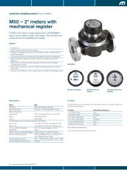
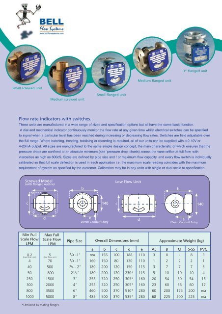
3” flanged unitMedium flanged unitSmall screwed unitMedium screwed unitSmall flanged unit<strong>Flow</strong> <strong>rate</strong> <strong>indicators</strong> <strong>with</strong> <strong>switches</strong>.These units are manufactured in a wide range of sizes and specification options but all have the same basic function.A dial and mechanical indicator continuously monitor the flow <strong>rate</strong> at any given time whilst electrical <strong>switches</strong> can be specifiedto signal when a particular level has been reached during increasing or decreasing flow <strong>rate</strong>s. Switches are field adjustable overthe full range. Where batching, trending, totalising or recording is required, all of our units can be supplied <strong>with</strong> a 0-10V or4-20mA output. All sizes are manufactured to the same simple design concept, the main characteristic of which ensures that thepressure drops are confined to an absolute minimum (see ‘pressure drop’ charts) across the vane orifice at full flow, <strong>with</strong>viscosities as high as 600cS. Sizes are defined by pipe size and / or maximum flow capacity, and every flow switch is individuallycalib<strong>rate</strong>d so that full scale deflection is used in each application i.e. the maximum scale reading coincides <strong>with</strong> the maximumrequirement of system as specified by the customer. Calibration may be in any units <strong>with</strong> single or duel scale to specification.Screwed Model(<strong>with</strong> flanged outline)abLow <strong>Flow</strong> Unitbc140 c140de20mm Conduit Entryde20mm Conduit EntryMin FullScale <strong>Flow</strong>LPMMax FullScale <strong>Flow</strong>LPM0.2 54 7040 50050 800250 1500300 2000800 35001000 5000(low flow unit)(low flow unit)Pipe Size Overall Dimensions (mm) Approximate Weight (kg)a b c d e AL B CI S-SS PVC1 /4 -1” n/a 155 100 188 110 3 8 - 8 31 /4 -1” 160 150 80 130 110 1 2 2 2 13 /4 - 2” 180 200 120 150 115 3 7 7 7 32 1 /2” 180 200 120 230* 115 5 10 10 10 43” 255 320 250 305* 160 20 54 50 54 154” 255 320 250 305* 160 23 60 56 60 176” 460 500 370 510* 280 60 200 175 200 n/a8” 485 500 370 535* 280 68 225 200 225 n/a*Obtained by mating flanges.
FML300 B LP 3EE 1cS 16F10 S3 D1SERIES AND FLOW RATEFMC* = Low <strong>Flow</strong>FML* = Litres / MinFMB* = Imp. Gallons / MinFMG* = U.S. Gallons / MinFMM* = M3/ Hour*Add Full <strong>Flow</strong> Rate in UnitsMATERIAL OF MANUFACTUREAL = AluminumB = BronzeCI = Cast IronCIK = Cast Iron Nickel PlatedS = Carbon SteelSS = Stainless SteelPTFE* = PTFEPVC* = PVC*Only available up to 4” Port Connections and100 psi / 7 bar maximum pressure.Note: For materials and pressures not specified, pleaseconsult factory.PRESSURE RATINGLP = 300 psi / 20 bar maximumMP = 750 psi / 50 bar maximumHP = 3000 psi / 200 bar maximum**CI, CIK, S & SS onlyINDICATOR READ OUTME= Mechanical Pointer only3EE= SPDT 3 Wire Switch3EEG= SPDT 3 Wire Switch <strong>with</strong> Gold Contacts3EE(ATEX3) = SPDT Explosion Proof Micro Switch to ATEX zone 33EE(ATEX2) = SPDT Explosion Proof Switch to ATEX zone 26EE(ATEX2) = DPDT Explosion Proof Switch to ATEX zone 2AIR= Pneumatic SwitchPOT= Potentiometer (Specify Rating)OUT= 4-20 mAmp OutputTOT= Digital Rate TotaliserTOTX= Digital Rate Totaliser (ATEX)Note 1: All electrical boxes (apart from TOT & TOTX) also carry a Mechanical PointerNote 2: For 4 & 6 Wire Switches replace 3EE by 4EE or 6EENote 3: Manufactured to IP65 (NEMA 4) as standard (up to 2 1 /2”)3EE4EE6EECOM NO NCNO1NO2ELECTRICAL OPTIONSCODE: 3EEBasic single pole, double throw, 3 wire switch.1 15 Amp - 125, 250 or 480V.AC0.5 0.5 Amp - 125V.DC / 0.25 Amp - 250V.DCNC1NO2NC1NO1NO2NC2 COM2COM1CODE: 4EEContact arrangements is single-pole, double throw, double-break.10 Amp - 125 or 250V.AC0.3 Amp - 125V.DC / 0.15 Amp - 250V.DCCODE: 6EEDouble-pole, double throw <strong>switches</strong> simultaneously makeand break two independent circuits.10 Amp - 125 or 250V.AC0.3 Amp - 125V.DC / 0.15 Amp - 250V.DCCODE: AIRThis system offers an alternative safety arrangement for operation in explosiveatmospheres. Compressed air can be used to transmit an on / off signal from thedanger area, or to ope<strong>rate</strong> a klaxon inside the danger area.CODE: POTRemote read-out option (0-10V). Rating to customer’s specification, e.g. 1K, 2K etc.CODE: OUTA transducer can be connected to the potentiometer to give the required 4-20mAmp readout. Data Loggers or Recorders can be added to the system.The 3 and 6 wire <strong>switches</strong> described above are available in ATEX approvedexplosion proof versions, <strong>with</strong> the appropriate enclosure box. When two or more<strong>switches</strong> are assembled in one unit, they remain independently adjustable.Re-adjustments may be carried out in the field.PORT CONNECTIONS2 = 1 /4 "4 = 1 /2”6 = 3 /4”8 = 1"10 = 1 1 /4”12 = 1 1 /2"16 = 2"20 = 2 1 /2”24 = 3"32 = 4"48 = 6"64 = 8"Air & Gas ApplicationsOur flow <strong>switches</strong> can also be used to measure gasflows in exactly the same way as liquid flows.Whenenquiring for such an application the following informationwill be required:Specific gravity of the gasMaximum flow volumeOperating temperatureOperating pressureFLOW DIRECTIONSD1 = D2 =D3 = D4 =‘O’ RING SEAL MATERIALS1 = Buna (-40°C +110°C)S2 = EPDM (-40°C +150°C)S3 = Viton (-20°C +200°C)S4 = PTFE (-100°C +250°C)S5 = Perlast (-15°C +330°C)Standard Threads are BSP, for NPT add - NFor Flanged Connections add one of the followingcodes:F10 (PN10)F16 (PN16)F25 (PN16)F40 (PN40)F150 (ANSI 150)F300 (ANSI 300)F600 (ANSI 600)FADFEFFSizes 1 /4” - 2" are Screwed orFlanged.For Flanged Bodies, add relevantcode letters (shown below).Sizes 2 1 /2" - 8". Standard units haveFlanged Bodies - add relevant codeletters (shown below).Cast Iron and Steel mating flangesare available:For Screwed, add - SFor Socket Weld, add - SWAlternative Pressure Ratings inBS4504 / DIN2632-5Alternative Pressure Ratings inBS1560 / ANSI B16.5Alternative Pressure Ratings inBS10For special flange connections, please enquire at factoryVISCOSITY AT OPERATING TEMPEATUREState units and scaleeg. Water is 1 Centistoke (cS)Maximum rating should not exceed 600cS
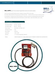
Variable Orifice / Swing Vane PrincipleThe flow switch body houses a spring-loaded valve plate (vane) which pivots off-centre in ahemispherical cavity. Thus the vane and cavity have a variable area orifice relationship. This gives both ahigh flow range and a linear relationship between flow <strong>rate</strong> and vane displacement. The vane indirectly ope<strong>rate</strong>s both theindicating needle and an adjustable cam, which in turn triggers the micro-switch at any chosen setting of flow <strong>rate</strong>. Two<strong>switches</strong> can be supplied to provide high and low (or 'low-low') flow switching.PRINCIPLE FEATURES & BENEFITS• All metal construction - no tubes of glass or plastic to break.• Spring loaded mechanical design - requires no straight pipe run and not affected by orientation.• Limited movement on internal parts - minimal wear and down time.• Modular design - reduces maintenance costs, down time, and production loss.• Direct indication & field adjustable switch(es) - monitors critical flows and provides alarm(s).• 1% of <strong>rate</strong> repeatable switch set point - accu<strong>rate</strong> & reliable through all operation cycles.• Weatherproof enclosure box to IP65 (Nema 4).Small Series• <strong>Flow</strong> through design - minimal pressure loss.2.42.1• Individually calib<strong>rate</strong>d to customer specification - ensures accuracy.1.81.5• Adjustable under operating conditions.1.2• Scale is in units (e.g litres/minute).0.90.6• Large range of body materials available.0.3• Size range from 8mm ( 1 0.0/4”) to 200mm (8").0 10 20 30 40 50 60 70<strong>Flow</strong> Rate (Ipm)• May be installed in any position.• Orientation of enclosure box easily changed.Medium Series5.0• High switch rating - 10 to 15 Amps.4.54.0• ATEX approved Explosion-proof models available.3.53.0• Will pass twice the maximum indicated flow.2.52.0• Acts as non-return value.1.5ApplicationsWater (clean or dirty) Petroleum Based Oils SolventsDe-mineralised Water Synthetic Based Oils PaintsDe-ionized Water Coolants Corrosive Fluids Air & GasesPressure Drop (psi)Pressure Drop (psi)1.00.50.00 50 100 150 200 250 300 350 400 450 500<strong>Flow</strong> Rate (Ipm)Low <strong>Flow</strong> / Piston Style PrincipleA fixed tapered needle passing through an orifice in the face of a piston, completely sealsthe port to port connection when the piston is seated. As flow commences the piston isdisplaced against a 4 psi differential spring and moves over the tapered section of theneedle, thus permitting flow through the orifice. Only the needle taper configuration needsto be changed to accommodate any specified viscosity and maximum flow requirement, thusthe full deflection of the unit can be used for all applications.PRINCIPLE FEATURES & BENEFITS• Suitable for liquid or gas applications.• 4-20mA and 0-10v outputs available.• Measures down to 200 cc/minute (at 1cS).• Cannot be switched on cold start-up.• Measures down to 50 cc/minute (at 20cS or higher). • Suitable for 20, 50 and 200 bar maximum pressures.• Maximum capacity 5 litres/minute.• Inline design, 1 /4” to 1” BSP or NPT female inlet and outlet.• Electrical switch(es), and/or calib<strong>rate</strong>d indication. • May be mounted in any orientation.
Visual <strong>Flow</strong> Indicatorgo <strong>with</strong> the flow…The ‘Rising Ball’ and ‘Spinner’: thelatest design of low cost,‘entry level’ <strong>Flow</strong> Indicators.These robust <strong>indicators</strong> out perform other visual flowinstruments by a considerable margin.When calib<strong>rate</strong>d flow<strong>indicators</strong> are not needed these units will satisfy most requirements<strong>with</strong>in pipe sizes 8mm to 40mm. Being constructed from high qualitymaterials these in-line <strong>indicators</strong> will meet the needs of many chemicalapplications, as well as being suitable for water, oil and gases.Visual flow <strong>indicators</strong> start to ope<strong>rate</strong> once flow has commenced, this can be from as low as 0.1 LPM.The exceptional ratio betweenmaximum and minimum flow is achieved by carefully toleranced manufacture.When operators require a visual confirmation in their pipework, forlubrication and coolant flow, these simple <strong>indicators</strong> can provide a cost effective solution for plant protection. Including one of these inexpensivefittings to pipework on a power-plant may save thousands of pounds in downtime and bearing or pump impeller replacement. Add to this the safetyimplications resulting from plant failure and the true benefits may be fully appreciated.Features & Benefits• Suitable for water, gas and other clear liquids.• Excellent chemical compatibility due to thematerials of construction• Ope<strong>rate</strong>s over a wide flow range.• Competitively priced.• Off the shelf deliveries.• No routine maintenance needed.• Unrivalled flow and pressure drop performance.• Manufactured in stainless steel or bronze.ApplicationsThis flow indicator is primarily used in plant protection applications to show lubricationor coolant flow to pumps, compressors or engines. Applications include:• Early warning of overheating, bearing or seal failure.• Detecting changes in the colour and condition of liquids during processing.• Pump, compressor and diesel protection.• Ensuring that flow of cooling water is maintained to specialised welding equipment.• Indication of air entrainment.• Indicating chemical dosing on water treatment facilities.• Showing the presence of condensate in steam return lines.• Maintaining demineralised water rinsing essential to electronics components manufacture..RISING BALL SPINNER Technical DataFigure 1BACFigure 2BACMaterials: Body - Stainless Steel (ANC4B) or - Bronze (LG2)Clamp Ring - Stainless Steel or BronzeSpinner - PPS plastic, ‘canary yellow’Ball - PTFE ’Teflon’Glass Dome - Annealed Borosilicate‘O’ Ring - Viton (standard), PTFE (optional)Gasket - Klingersil (C-4400)Fasteners - Stainless SteelPressure: - 16 Bar (maximum working pressure)Temperature: - 200°C (maximum working temperature)Connections: - BSP(F) parallel and NPT(F) taper<strong>Flow</strong> Direction: - Rising Ball: Horizontally Mounted - Single Direction- Spinner: Horizontal/Vertical Mounting - Bi-DirectionalEvery effort will be made to meet any special connections and material requirements.Size<strong>Flow</strong> RequirementsMin <strong>Flow</strong>Out of SocketPressure Drop -2 m/secmm l/min l/min bar8 0.1. 1.0 0.1310 0.1 1.0 0.1615 0.1 1.0 0.1920 2.4 5.2 0.1625 2.7 5.5 0.4032 11.0 16.0 0.2040 16.0 21.0 0.23Table 1 Table 2Dimensions and WeightsBoreSizeWeight‘A' Overall Length‘B' Width (Clamp)‘C' Overall Heightmm inch kg mm mm mm8 1/4 0.72 76 63 7910 3/8 0.69 76 63 7915 1/2 0.65 76 63 7920 3/4 1.30 89 63 9525 1 1.25 89 63 9532 1 1 /4 2.50 117 75 12540 1 1 /2 2.35 117 75 125Size<strong>Flow</strong> RequirementsMin <strong>Flow</strong>Max flowPressure Drop -2 m/secmm l/min l/min bar8 0.7 30 0.1410 0.8 40 0.1615 1.0 55 0.2220 1.2 90 0.1925 1.5 140 0.50BoreBoreSizeWeightA'OverallDimensions and WeightsSizeWeight‘A' Overall Length‘B' Width (Clamp)‘C' Overall Heightmm inch kg mm mm mm8 1/4 0.68 76 63 6510 3/8 0.65 76 63 6515 1/2 0.62 76 63 6520 3/4 1.25 89 63 8325 1 1.20 89 63 83LengthFor further information contact:Tel: 01296 658 600 Fax: 01296 658 515Email: sales@bellflowsystems.co.uk www.bellflowsystems.co.uk<strong>Bell</strong> <strong>Flow</strong> <strong>Systems</strong> Limited, Building 426 Westcott Venture ParkWestcott, Aylesbury, Bucks HP18 0XB