

section - Bitsavers
section - Bitsavers
section - Bitsavers
- No tags were found...

Create successful ePaper yourself
Turn your PDF publications into a flip-book with our unique Google optimized e-Paper software.
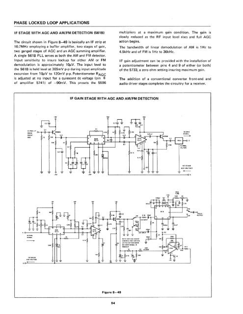
PHASE LOCKED LOOP APPLICATIONSIF STAGE WITH AGC AND AM/FM DETECTION (5618)The circuit shown in Figure 8-49 is basically an I F strip at10.7MHz employing a buffer amplifier, two stages of gain,two ganged stages of AGe and an AGe summing amplifier.A single 561 B PLL serves as both the AM and FM detector.Input sensitivity to insure lockup for either AM or FMdemodulation is approximately 101lV. The input level tothe 561 B is held level at 305mV p-p during input amplitudeexcursion from 10llV to 120mV p-p. Potentiometer RAGeis adjusted at no input for a quiescent dc voltage (pin 6of ampl ifier 5741) of -90m V. Th is presets the 5596multipliers at a maximum gain condition. The gain isslowly reduced as the R F input level rises and full AGeaction begins.The bandwidth of linear demodulation of AM is 1 Hz to4.5kHz and of FM is 1 Hz to 36kHz.I F gain adjustment can be provided with the installation ofa potentiometer between pins 4 and 9 of either (or both)of the 5733, a zero ohm setting insuring maximum gain.The addition of a conventional converter front-end andaudio driver stages completes the circuitry for a receiver.IF GAIN STAGE WITH AGC AND AM/FM DETECTION+6V+6V+6V0.1~~~~HZ IF o-..-il-..--£FRONTEND75 13K10.7MHzSIGNAL510IN9141ST STAGEAGe VOLTAGE-6V-6VFINETUNE100MUDIOOUTPUTNOTE, SET AGC ADJUSTCONTROL FOR 0.09 VDC0.2 AT PIN 6 OF 5741 WHENINPUT SIGNAL IS1ST STAGEAGCVOLTAGE100I INOAGeADJUSTFigure 8-4954


