
Create successful ePaper yourself
Turn your PDF publications into a flip-book with our unique Google optimized e-Paper software.
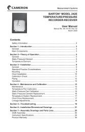
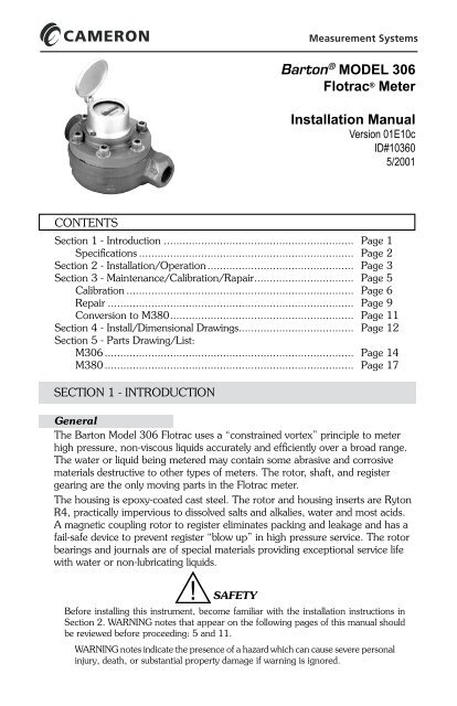
Barton ® MODEL 306<strong>Flotrac</strong> ® <strong>Meter</strong>Installation ManualVersion 01E10cID#103605/2001CONTENTSSection 1 - Introduction.............................................................. Page 1Specifications...................................................................... Page 2Section 2 - Installation/Operation................................................ Page 3Section 3 - Maintenance/Calibration/Rapair................................ Page 5Calibration.......................................................................... Page 6Repair................................................................................ Page 9Conversion to M380........................................................... Page 11Section 4 - Install/Dimensional Drawings..................................... Page 12Section 5 - Parts Drawing/List:M306................................................................................. Page 14M380................................................................................. Page 17SECTION 1 - INTRODUCTIONGeneralThe Barton Model 306 <strong>Flotrac</strong> uses a “constrained vortex” principle to meterhigh pressure, non-viscous liquids accurately and efficiently over a broad range.The water or liquid being metered may contain some abrasive and corrosivematerials destructive to other types of meters. The rotor, shaft, and registergearing are the only moving parts in the <strong>Flotrac</strong> meter.The housing is epoxy-coated cast steel. The rotor and housing inserts are RytonR4, practically impervious to dissolved salts and alkalies, water and most acids.A magnetic coupling rotor to register eliminates packing and leakage and has afail-safe device to prevent register “blow up” in high pressure service. The rotorbearings and journals are of special materials providing exceptional service lifewith water or non-lubricating liquids.SAFETYBefore installing this instrument, become familiar with the installation instructions inSection 2. WARNING notes that appear on the following pages of this manual shouldbe reviewed before proceeding: 5 and 11.WARNING notes indicate the presence of a hazard which can cause severe personalinjury, death, or substantial property damage if warning is ignored.
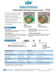
In-line examination of all parts exposed to the process liquid is simple. Firstdepressurize the meter. Then by unscrewing six cap screws and removing themeter cover, the rotor can be slipped off for inspection or replacement.SpecificationsM306 Cross-section View2
SECTION 2 - INSTALLATION/OPERATIONGeneralThe instrument should be inspected at time of unpacking to detect any damagethat may have occurred during shipment.Pre-checkThe Model 306 <strong>Flotrac</strong> <strong>Meter</strong> was calibrated at the factory on clean waterbefore shipment. If further calibration is required, contact the nearest <strong>Cameron</strong>representative.Mounting1. Piping - The meter has one-inch NPT female threads in both inlet and outletports. The end of the inlet pipe should be filed smooth and square beforefitting to the meter for best accuracy.2. Position - The <strong>Flotrac</strong> meter may be mounted in either horizontal or verticalpiping. When mounted horizontally, the dial face should be upward.3. Bypass - The meter installation should include a bypass line to allowmeter inspection or repair without interrupting the flow of liquid. Refer toillustration below:4. Control Valve - flow rate control valve must always be installed downstreamfrom <strong>Flotrac</strong> meter. Experience has indicated that pressure drop acrosscontrol valves will cause undue turbulence and, in some cases, vaporizationof the liquid. This may result in cavitation and erroneous meter readings.OperationBasic TheoryLiquid flowing through the meter turns the rotor. The rotor is magneticallyconnected to a shaft, which in turn is connected through gears to a readoutregister. The turns of the rotor are indicated on the register.<strong>Meter</strong> Operation (See M306 Cross-section View on previous page)The process liquid enters the metering chamber through the inlet connection.As the liquid follows the 360 degree loop, it is separated into two equal streams.These two streams are forced into a series of vortices in the body and coverinserts and cause the rotor to rotate in proportion to the rate of flow.Rotation of the rotor is transmitted through the shaft and gears to the registerassembly, where the liquid flow is indicated.3
Both liquid streams rejoin at the meter outlet which is in direct line with themeter inlet.Startup ProcedureA. Practical ConsiderationsThe following practices should be observed when installing and starting a<strong>Flotrac</strong> meter. See cross-sectional illustration above and by-pass locationdrawing at the top of the next page.1. StrainerA strainer should be installed upstream from the <strong>Flotrac</strong> meter if rockfragments, weld slag or debris may be introduced into the flow line.Some sand is permissible.2. Water TreatmentIf dissolved calcium carbonates (CaC0 3 ) or salts are excessive, treatmentis required to prevent scale buildup on the rotor journal andhousing parts.3. Air EliminatorIf the liquid stream contains substantial amounts of dissolved gas orvapors, an air eliminator should be installed upstream from the meterfor the best accuracy.B. Startup1. Before installing the <strong>Flotrac</strong> meter, purge flow lines to remove debris.2. After installation of the meter, close isolation valves and open bypassvalve. Flow through the bypass manifold for sufficient time to eliminateair in the flow line. High velocity air or gas can cause rotor bearingdamage.3. Open isolation valve ahead of the meter slowly to eliminate hydraulicshock while charging the meter with liquid. Open the valve to fullopen.4. Open isolation valve downstream to permit the meter to operate.5. Close the bypass valve.6. Adjust the downstream valve to provide the required flow rate throughthe meter.NOTE: The downstream isolation valve may be used as a flow controlvalve.4
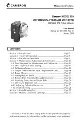
SECTION 3 - MAINTENANCE/CALIBRATIONWARNINGA METER IN LINE SHOULD BE DISASSEMBLED ONLYAFTER PRESSURE IS REMOVED FROM THE LINE.Periodic MaintenanceRegular inspection and preventive maintenance should insure extended troublefreeoperation. The following procedure is suggested as a basis for a maintenanceprogram. However, the program should be adapted to the corrosivenessor abrasiveness of the metered liquid.1. Inspect rotor assembly every 50,000 barrels.2. Inspect tube seal every 50,000 barrels.3. Inspect support bearing every 50,000 barrels.4. Inspect the register assembly semiannually.5. Inspect body and 0-rings annually. If severe abrasion or corrosion is anticipated,inspect more frequently.LubricationThe input shaft, outboard bearing and pinion should be lubricated at least twicea year.A. Input ShaftLubricate with several drops of No. 10motor oil or equivalent.B. Outboard BearingThe oil impregnated bronze bearingrequires no additional lubrication.C. PinionAdd standard weight grease on pinionteeth and mating gear.Tools RequiredThe following tools are required to perform calibration and maintenance adjustmentson the Model 306:5
TroubleshootingIf trouble develops, the procedures listed in Table below will usually locate theproblem and suggest a solution. Normally, problems will be restricted to therotor assembly, magnetic drive coupling or register assembly.CalibrationThe Model 306 <strong>Flotrac</strong> <strong>Meter</strong> was calibrated at the factory using clean water. Ifsubsequent proving shows a change in the calibration constant, the meter can becorrected by changing the calibration gears.The required correction is determined by comparing the True Volume offluid passing through the meter during a proving procedure with the <strong>Meter</strong>edVolume shown on the register. The required correction is:The new pinion and input gears should be selected so that the percent changein gear ratio is as nearly equal to the correction as possible. This may be accomplishedwith the aid of U.S. Barrel Registers Table on page 7 or Liters/Cubic<strong>Meter</strong>s Registers Table on page 8).Example:Gear Combination................... Pinion - 18T,Input - 75TTrue Volume ........................... 100 Bbl<strong>Meter</strong>ed Volume...................... 104 BblThe required correction is:6
Using "US Barrels" Table below, move along the vertical axis (at P/I combination)to 18/75. As shown, selection of a new pinion input gear combinationwith a 17-tooth pinion gear and a 74-tooth input gear will result in a -4.28correction. The new metered volume will therefore be 104 x (1-0.0428) =99.55 gallons for a residual error of (100 -99.55)/100 or -0.45%, which iswithin specification.The "Liters/Cubic <strong>Meter</strong>s" Table on the next page is used in the same way tocorrect meters which have metric registers.Part numbers of the various pinion and input gear assemblies are provided inPart Number Table at the top of page 9.7
Gear Part NumbersRepairRepairs are readily made on the meter, either in-line or on the bench. Rememberthat all threads are right-handed, and that parts should be installed in reverseorder of removal. In addition, 0-rings should be inspected prior to reassembly,and replaced if cuts or swelling are evident.To protect the register, it should be removed by unscrewing two cover screws,lifting off the case, register and gasket.Repairs to the faceplate are limited to replacing the glass if it is broken. Thisrequires the installation of a new retaining ring, since the ring breaks whenremoved.Removal and installation procedures for major components are covered in thefollowing paragraphs:A. Rotor Replacement1. To remove rotor - Remove six body screws with 3/8" hex key, lift offmeter cover (with its O-ring in place), then slip old rotor off journal tubenoting direction of rotor blades.2. To install rotor - Place rotor on journal tube with flat side of bladesfacing fluid now, as noted during disassembly, slide cover with its 0-ringand rotor into body cavity with dowel pin aligned with cover. The 0-ringshould fit into its groove without pinching and the body cap screwsevenly tightened.B. Journal Tube Replacement1. To remove tube assembly - If the meter is in its normal position,with the register up, the tube can be removed without taking the coveroff. Taking the 7/8" wrench, unscrew the tube without bending theexposed shaft. The tube can then be lifted out of the cover, leavingthe rotor in the meter. The slight resistance that is felt is supplied bythe 0-ring.If the meter is not in the normal position, the tube should be removedafter taking the cover off, since the rotor will not remain centered afterthe tube is withdrawn.9
B. Journal Tube Replacement (continued)2. To install the tube assembly - Align the rotor with the tube, insertthe tube into the cover with care not to pinch the O-ring as it slides intoplace, and tighten the tube with the wrench.NOTE: The cover register cavity must be dry at all times.C. Input Gear and Pinion Replacement1. To remove the input gear and pinion - First remove the journaltube assembly as instructed in the preceeding section. With a 1/32”punch, drive the pinion spiral pin from the shaft assembly and removethe pinion. With a small screwdriver, loosen the input gear set screwsand remove the input gear from the input gear shaft.NOTE: For the proper combinations of input gear and pinion, refer toGear Selection Tables on pages 7 and 8.2. To install the input gear and pinion - Reinstallation is accomplishedby reversing the procedure described in the preceeding paragraph.D. Output Shaft Bearing Replacement1 . To remove shaft assembly - After removing the register, use a9/16" socket or box end wrench to unscrew the bearing supportassembly (including the shaft), driven magnet and output pinion. Toremove the shaft from the assembly it is necessary to push out thesmall pin in the pinion with a 1/32" punch, supporting the shaft soit will not be bent. After sliding pinion off, remove the shaft from thebearing support. If required, the magnet can be taken off by usingTruarc Pliers, No. 52A, to take the grip ring off the shaft.2. To install the shaft assembly - The bearing support and its bearingsare replaced as a unit, the shaft inserted with the magnet at the endopposite the wrench hexagon, the pinion is placed with its pin holealigned with that of the shaft, and the pin installed with care againnot to bend shaft. The assembly, with 0-ring in place, should then beinserted into the journal tube and tightened.E. Insert Replacement1. To remove inserts - Remove the meter cover, slip off the rotor,unscrew two screws in each insert (note porting orientation), and liftout. Calcium carbonate deposits will make this difficult if the water isnot treated. Each insert has a thrust washer that can be removed withlight force. These washers can be reversed to present a new surface tothe rotor, or replaced-if worn.2. To install inserts - Place each insert with its washer in the properhousing with porting oriented properly. Fasten with the flat headscrews below the insert surface. Reassemble the rotor, cover, bodyO-ring, and fasten down as before.F. RegisterIf register is damaged, replacement of complete register is recommended.10
Conversion to Model 380The Model 306 <strong>Flotrac</strong> <strong>Meter</strong> (capacity 9-90 gpm) can be converted to a Model380 Flow <strong>Meter</strong> (capacity 1.5-15 gpm) by replacing the parts noted in theTable below. When making this conversion, refer to M306 and M380 PartsDrawings and Parts Lists in Section 5 (starting on page 14). Replace worn partsas necessary (refer to Repair Procedure starting on page 9).WARNINGREMOVE ALL LINE PRESSURE FROM THE METERBEFORE REMOVING THE METER COVER CAP SCREWS.11
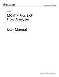
SECTION 4 - INSTALL/DIMENSIONAL DRAWINGSModel 306Note: Measurements are in inches.12
SECTION 5 - PARTS DRAWING/LIST306 Parts Drawing14
306 Parts List15
SECTION 6 - PARTS DRAWING/LIST (continued)306 Parts List (continued)16
380 Parts Drawing17
SECTION 6 - PARTS DRAWING/LIST (continued)380 Parts List18
M380 Parts List (continued)19
Product WarrantyA. Warranty<strong>Cameron</strong> International Corporation ("<strong>Cameron</strong>") warrants that at the time of shipment, theproducts manufactured by <strong>Cameron</strong> and sold hereunder will be free from defects in materialand workmanship, and will conform to the specifications furnished by or approved by<strong>Cameron</strong>.B. Warranty Adjustment(1) If any defect within this warranty appears, Buyer shall notify <strong>Cameron</strong> immediately.(2) <strong>Cameron</strong> agrees to repair or furnish a replacement for, but not install, any productwhich within one (1) year from the date of shipment by <strong>Cameron</strong> shall, upon test andexamination by <strong>Cameron</strong>, prove defective within the above warranty.(3) No product will be accepted for return or replacement without the written authorizationof <strong>Cameron</strong>. Upon such authorization, and in accordance with instructions by<strong>Cameron</strong>, the product will be returned shipping charges prepaid by Buyer. Replacementsmade under this warranty will be shipped prepaid.C. Exclusions from Warranty(1) THE FOREGOING WARRANTY IS IN LIEU OF AND EXCLUDES ALL OTHER EX-PRESSED OR IMPLIED WARRANTIES OF MERCHANTABILITY, OR FITNESS FORA PARTICULAR PURPOSE, OR OTHERWISE.(2) Components manufactured by any supplier other than <strong>Cameron</strong> shall bear only the warrantymade by the manufacturer of that product, and <strong>Cameron</strong> assumes no responsibilityfor the performance or reliability of the unit as a whole.(3) "In no event shall <strong>Cameron</strong> be liable for indirect, incidental, or consequential damagesnor shall the liability of <strong>Cameron</strong> arising in connection with any products sold hereunder(whether such liability arises from a claim based on contract, warranty, tort, or otherwise)exceed the actual amount paid by Buyer to <strong>Cameron</strong> for the products delivered hereunder."(4) The warranty does not extend to any product manufactured by <strong>Cameron</strong> which has beensubjected to misuse, neglect, accident, improper installation or to use in violation of instructionsfurnished by <strong>Cameron</strong>.(5) The warranty does not extend to or apply to any unit which has been repaired or alteredat any place other than at <strong>Cameron</strong>'s factory or service locations by persons not expresslyapproved by <strong>Cameron</strong>.Product BrandBarton® is a registered trademark of <strong>Cameron</strong> International Corporation ("<strong>Cameron</strong>").M E A S U R E M E N T S Y S T E M SFormerly: NuFlo Measurement Systems • Barton Instrument Systems • Caldon, Inc.HOUSTONHEAD OFFICE281.582.9500NORTHAMERICA1.800.654.3760ms-us@c-a-m.comASIAPACIFIC603.2287.1039ms-asiapacific@c-a-m.comEUROPE,MIDDLE EAST& AFRICA44.1243.826741ms-uk@c-a-m.comU S A • C A N A D A • U K • S C O T L A N D • C H I N A • U A EA L G E R I A • M A L A Y S I A • S I N G A P O R E • w w w . c - a - m . c o m / f l o