Rest Man 1 to 35.qxp - Zimmer Dental
Rest Man 1 to 35.qxp - Zimmer Dental
Rest Man 1 to 35.qxp - Zimmer Dental

You also want an ePaper? Increase the reach of your titles
YUMPU automatically turns print PDFs into web optimized ePapers that Google loves.
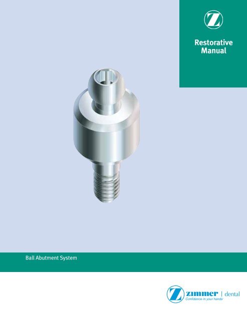
Ball Abutment System<strong>Rest</strong>orative<strong>Man</strong>ual
86 <strong>Rest</strong>orative options with Ball AbutmentsBall Abutments are used in attachment-retained, tissue-supported res<strong>to</strong>rations where the patient is fully edentulous in the arch <strong>to</strong> beres<strong>to</strong>red. The extra-coronal type of attachment mechanism consists of a one-piece abutment with a superior ball projection secured <strong>to</strong> theimplant. A Metal Housing [CAH] and retentive Nylon Liner [CAN] mechanically retained within the Metal Housing, collectively referred <strong>to</strong> asthe Cap Attachment [CA], is fixed within the patient’s denture. The inner receptacle of the Nylon Liner actsasthe 360-degree universalrotational connection between the denture and the abutment/implant assembly and allows for only slight compressive vertical movement.These abutments can be processed in<strong>to</strong> the denture either in a chairside pick-up technique or a labora<strong>to</strong>ry technique. Both techniques willbe discussed in this section.This type of res<strong>to</strong>ration requires sufficient depth of the posterior vestibule <strong>to</strong> protect the abutment/implant assembly from excessivelateral/horizontal force during mastication (Fig 1a-c). It is recommended <strong>to</strong> use implants with a length in excess of 12mm and abutmentheights should be kept <strong>to</strong> a minimum <strong>to</strong> maintain an acceptable implant/abutment height ratio. Therefore single-arch fully edentulouspatients with excessive resorption of the edentulous ridge might not be candidates for a res<strong>to</strong>ration inclusive of this type of abutment system.In most cases the res<strong>to</strong>ration is done utilizing two implants with corresponding Ball Abutments placed in the canine area, creating afulcrum around which the attached denture will rotate (Fig. 1d). Absolute parallelism is not a prerequisite for success as the rotationalaspect of the Cap Attachment on the ball component allows for adjustment of up <strong>to</strong> 28 degrees of relative divergence between implants.It should be noted that the long-term stability and maintenance of the retentive connection is reliant on three-dimensional alignment ofthe abutments and Cap Attachments (as shown below, Fig. 1e-1f) for increased longevity and success:1) The implants should be placed anterior/posteriorly so that the fulcrum line through the center of the components is parallel <strong>to</strong> themandibular hinge axis (Fig. 1e).2) The implants should be placed vertically so that the <strong>to</strong>ps of the metal housings are parallel <strong>to</strong> the occlusal plane of the patient’s dentureand corresponding opposing arch (Fig. 1f).3) The implants should be parallel <strong>to</strong> each other along their long axis and perpendicular <strong>to</strong> the plane of occlusion <strong>to</strong> be in optimumposition (Fig. 1g).Fig. 1aFig. 1bFig. 1cFig. 1d<strong>Man</strong>dibularHinge AxisOcclusal PlaneFig. 1eFig. 1fFig. 1g
Vertical height requirements for Ball Abutments87Ball Abutment for Tapered Screw-Vent, Screw-Vent and AdVent Implant SystemsBall Abutments are manufactured from titanium alloy and come packaged with the stainless steel Cap Attachment Housing [CAH] and CapAttachment Nylon Liner [CAN]. The abutments for the Tapered and Straight Screw-Vent 3.5 and 4.5mmD Platform Implants are available inthree collar heights (2mmL, 4mmL and 6mmL). The 5.7mmD platform Tapered Screw-Vent and AdVent Implant abutments have collar heightsof 2mm and 4mm only. The 4.5mmD platform AdVent Implant System, however, has only one collar height (1mmL) which can be utilized withor without the AdVent Extender [AVE] <strong>to</strong> create variable heights, depending on the depth of implant placement and surrounding soft tissue.The Ball Abutment collar is regularly placed 1mm supragingival and has a coronal diameter of 4.5mm, while the ball component itself is2.5mmD. When assembled, the vertical height of the Cap Attachment [CA] above the coronal aspect of the Ball Abutment collar is 4.28mmand its diameter is 5.00mm. Care should be taken <strong>to</strong> ensure sufficient denture acrylic surrounds the housing <strong>to</strong> prevent it from perforatingthe denture during function.Denture Acrylic(1.5-2mmL minimum)Denture Acrylic(1.5-2mmL minimum)NylonLiner4.28mmNylonLinerMetalHousing4.28mmMetalHousingAbutment Collar Height(1mmL or 3mmL withAdVent Extender [AVE])4.5mmDBallAbutment2.0mm4.5mmDBallAbutmentAbutment Collar Height(2mmL, 4mmL or 6mmL)3.0mm(variable)ImplantInterfaceBone HeightImplantInterfaceImplantImplantTapered Screw-VentTwo-Stage ImplantAdVentOne-Stage Implant
88 Components for Ball Abutment SystemBall Abutment TopLabora<strong>to</strong>ry TechniqueChairside TechniqueBall AbutmentTransfer[BAT]This process cannot be utilizedwith the 5.7mmD platformimplant systems.ChairsidePick-UpBall AbutmentReplica[BAR]Cap AttachmentTransfer[CAT]Cap Attachment[CA](Included with allBall Abutments)MetalHousingNylon LinerCap Attachment [CA] assemblies are includedwith the Ball Abutment, and consist of a MetalHousing and retentive liner. ReplacementHousings [CAH] and Nylon Liners [CAN] arealso available. A more rigid Retentive Liner[CAN-G] is also available.
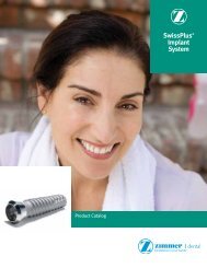
Ball Abutment System: labora<strong>to</strong>ry technique — Fabricating and utilizing a cus<strong>to</strong>m tray89Fabricating a cus<strong>to</strong>m trayPrior <strong>to</strong> attaching the abutments, make a full-arch, alginate impression ofthe Healing Collars and edentulous areas. Send the impression <strong>to</strong> thelabora<strong>to</strong>ry for fabrication of a working cast and an impression tray with aspacer <strong>to</strong> accommodate the Ball Abutment Transfers. Fabricate the cus<strong>to</strong>mtray with light-cured or au<strong>to</strong>polymerizing tray material. The patient’s existing,modified overdenture can continue <strong>to</strong> be worn during the labora<strong>to</strong>ry phase.Alternatively, select a s<strong>to</strong>ck tray <strong>to</strong> provide access for the transfers, and molda border with greenstick compound material.Attaching the ball componentsRecall the patient when the cus<strong>to</strong>m tray is ready. Remove the HealingCollars or Surgical Cover Screws with the 1.25mmD Hex Tool. Select BallAbutment components according <strong>to</strong> the implant type and transmucosalheight requirements. Place the selected Ball Abutments in<strong>to</strong> the implantsand tighten with <strong>to</strong> 30 Ncm with a calibrated <strong>to</strong>rque wrench.Seating the transfersPress the Ball Abutment Transfers [BAT] for all 4.5mmD collar componentson<strong>to</strong> the Ball Abutments. This step cannot be done on the 5.7mmD platformimplant systems.The transfer will engage the outer portion of the abutment beneath theball for maximum stabilization. An elas<strong>to</strong>meric impression material isrecommended, such as vinyl polysiloxane. Inject light-body impressionmaterial around the Ball Abutments and fill the impression tray with heavierbodyimpression material. Place the loaded tray in<strong>to</strong> the patient’s mouthand allow the impression material <strong>to</strong> set according <strong>to</strong> the manufacturer’srecommendations. Remove the impression from the mouth.Completing the transfer procedureRemove the Ball Abutment Transfers from the Ball Abutments, press themon<strong>to</strong> the Ball Abutment Replicas [BAR], and insert them back in<strong>to</strong> theimpression holes. A double-click indicatesthat the transfers are fully seated.Make an opposing-arch impression. Send all the materials <strong>to</strong> the labora<strong>to</strong>ryfor fabrication of a stabilized baseplate with occlusal registration rim.
90 Ball Abutment System: labora<strong>to</strong>ry technique — Fabricating a stabilized baseplate and bite rimFabricating a stabilized baseplate and bite rimPour the impression in die s<strong>to</strong>ne. Remove the tray from the cast and theBall Abutment Transfers from the Ball Abutment Replicas now incorporatedwithin the working cast.Press-fit the yellow Cap Attachment Transfers [CAT] on<strong>to</strong> the Ball AbutmentReplicas in the working cast. Place the Cap Attachment Housings [CAH](included with the Ball Abutments) on<strong>to</strong> the Cap Attachment Transfers.Fabricating a stabilized baseplate and bite rimRotate the assembled housings and transfers up <strong>to</strong> 28° <strong>to</strong> create relativeparallelism for a common path of draw. Block out the undercuts beneath thehousing assemblies with an appropriate silicone or wax material.Incorporating the housings in<strong>to</strong> the baseplatePlace gel viscosity light-cure resin material on the Metal Housings and cure.Incorporate the housings in<strong>to</strong> a stabilized baseplate made from light-curedbaseplate resin. Create a wax occlusion registration rim on the stabilizedbaseplate. Place the assembly on the working cast and send it <strong>to</strong> the dentistfor fabrication of a stabilized bite registration.Making a stabilized bite registrationSnap the yellow Cap Attachment Transfers on<strong>to</strong> the Ball Abutments in thepatient’s mouth. Place the stabilized baseplate and occlusal registrationrim in<strong>to</strong> the patient’s mouth and allow the transfers <strong>to</strong> insert in<strong>to</strong> the MetalHousings in the baseplate. Make a bite registration with the stabilizedbaseplate and occlusion rim. Send the assembly <strong>to</strong> the labora<strong>to</strong>ry forfabrication of a stabilized denture wax try-in.
Ball Abutment System: labora<strong>to</strong>ry technique — Delivering the final prosthesis91Making a stabilized denture wax try-inAfter the labora<strong>to</strong>ry fabricates a stabilized denture wax-up, recall the patientfor try-in. Snap the yellow Cap Attachment Transfers on<strong>to</strong> the Ball Abutmentsin the patient’s mouth. Place the denture wax try-in in<strong>to</strong> the patient’s mouthand allow the transfers <strong>to</strong> insert in<strong>to</strong> the Metal Housings in the baseplate.Evaluate esthetics and phonetics, and verify that the wax-up fits passively.If changes in <strong>to</strong>oth position are prescribed, schedule additional try-inappointments until acceptable <strong>to</strong>oth arrangement is verified and approvedby dentist and the patient. Place the approved stabilized denture wax try-inon the working cast with the Cap Attachment Transfers and send it <strong>to</strong> thelabora<strong>to</strong>ry for final processing.Cap Attachment Instruments [CAI]Nylon Liner Insertion ToolNylon Liner Reaming Tool<strong>Man</strong>dril for Castable Ball PatternCap Attachment instrumentsA) Nylon Liner Insertion Tool: Used <strong>to</strong> carry and assist in the insertionof the Nylon Liner in<strong>to</strong> the Metal Housing.B) Reaming Tool: When the Nylon Liner is <strong>to</strong>o retentive for the respectivepatient, the Reaming Tool is inserted in<strong>to</strong> the liner and rotated in a clockwisedirection. This action reduces the amount of retention between theBall Component and the Cap Attachment by reducing the dimension of theliner’s inner walls. Care should be taken <strong>to</strong> do this in small increments soas not <strong>to</strong> eliminate the required retention levels of the Nylon Liner.C) Paralleling <strong>Man</strong>dril: Used by the technician in combination with a surveyor<strong>to</strong> align the castable ball patterns in the correct position when fabricatinga ball bar overdenture.Processing the final prosthesisWhen the processed denture returns from the labora<strong>to</strong>ry, retighten theBall Abutments <strong>to</strong> 30 Ncm with a calibrated <strong>to</strong>rque wrench. Place one NylonLiner [CAN] from the Cap Attachments [CA] on<strong>to</strong> the end of the insertion <strong>to</strong>ol.Use the Insertion Tool <strong>to</strong> press the Nylon Liner in<strong>to</strong> one of the metal housingsin the denture base. Check the retention of the liner by snapping the dentureon and off the ball component in the patient’s mouth. If necessary, use theReaming Tool <strong>to</strong> decrease the retention of the Nylon Liner. When adequateretention has been achieved, process the second Nylon Liner in the samemanner. Insert and adjust only one Nylon Liner at a time.Delivering the final prosthesisInsert the finished prosthesis in<strong>to</strong> the patient’s mouth and snap theincorporated Cap Attachments on<strong>to</strong> the Ball Abutments. Make finaladjustments <strong>to</strong> the occlusion. Instruct the patient in the use and care of theprosthesis, and provide oral hygiene instructions. Caution the patient not <strong>to</strong>use bleach on the prosthesis, which can damage the nylon Cap Attachmentliners. To prolong the use of the Nylon Liners, instruct the patient <strong>to</strong> insertand remove the overdenture by lifting the prosthesis vertically instead oflaterally or by twisting. If the Nylon Liners lose retention, they can be easilyreplaced at a recall appointment. For patients who require stronger CapAttachment retention, gray Nylon Liners [CAN-G] with a more rigid retentionare also available.
92 Ball Abutment System: chairside technique —Attaching Cap Attachments <strong>to</strong> an existing dentureAttaching the ball componentsRecall the patient when the cus<strong>to</strong>m tray is ready. Remove the HealingCollars or Surgical Cover Screws with the 1.25mmD Hex Tool. Select BallAbutment Components according <strong>to</strong> the implant type and transmucosalheight requirements. Place the selected ball components in<strong>to</strong> theimplants and tighten <strong>to</strong> 30 Ncm with a calibrated <strong>to</strong>rque wrench.Preparing the housings for pick-upSnap the yellow Cap Attachment Transfers [CAT] on<strong>to</strong> the Ball Abutments.Place the Cap Attachment Stainless Steel Housings [CAH] over the transfers.Preparing the housings for pick-upRotate the assembled Cap Attachment Transfers [CAT] and Metal Housings[CAH] on the Ball Abutments up <strong>to</strong> 28° <strong>to</strong> create relative parallelism for acommon path of draw. Try and ensure that the components are alignedtaking in<strong>to</strong> consideration the occlusal plane of the denture; this will helpwith the smooth rotation of the denture around the Ball Abutment.Preparing the denture for pick-upSeat the denture in<strong>to</strong> the patient’s mouth <strong>to</strong> determine the locations of theMetal Housings relative <strong>to</strong> the tissue-bearing surface of the prosthesis.Remove the denture from the patient’s mouth and mark the locations of theassembled housings on the bot<strong>to</strong>m of the prosthesis. Relieve the areas overthe housings with an acrylic bur until the denture can be fully seated in thepatient’s mouth without contacting the Metal Housings.Small relief holes can be drilled through the <strong>to</strong>p of the recess <strong>to</strong> allowexcess acrylic <strong>to</strong> exude through.
Ball Abutment System: chairside technique — Adding Cap Attachments <strong>to</strong> an existing denture93Preparing the housings for pick-upBlock out the undercuts beneath the housing assemblies with anappropriate silicone or wax material, taking care not <strong>to</strong> change theorientation of the housings on the Ball Abutment.Processing the housings in<strong>to</strong> the denture baseAu<strong>to</strong>polymerizing acrylic is recommended for the pick-up. It flows betterthan a light-cured resin and engages the undercuts on the outside of theMetal Housings [CAH] more efficiently. Place a small amount ofau<strong>to</strong>polymerizing acrylic in<strong>to</strong> the dry, relieved areas within the denturebase. Also place a small amount of acrylic directly on the <strong>to</strong>ps of thehousings. Place the denture over the housings in the mouth and instructthe patient <strong>to</strong> bite lightly in centric occlusion. Remove the denture after theacrylic sets. Fill in any voids remaining around the processed housings withadditional au<strong>to</strong>polymerizing acrylic.Processing the Nylon Liners in<strong>to</strong> the denture baseRemove the yellow Cap Attachment Transfers from the Ball Abutments inthe patient’s mouth. Place one Nylon Liner [CAN] from the Cap Attachments[CA] on<strong>to</strong> the end of the insertion <strong>to</strong>ol from the Cap Attachment Instruments[CAI]. Press a Nylon Liner in<strong>to</strong> the Metal Housing in the denture base.Check the retention of the liner by snapping the denture on and off the ballcomponent in the patient’s mouth. If necessary, decrease the retention ofthe liner by inserting the Reaming Tool from the Cap Attachment Instrumentsin<strong>to</strong> the liner and turning it clockwise <strong>to</strong> reduce the retention of the liner’sinner walls. When adequate retention has been achieved, process thesecond liner in the same manner. Insert and adjust only one Nylon Linerat a time.Delivering the final prosthesisInsert the finished prosthesis in<strong>to</strong> the patient’s mouth and snap theincorporated Cap Attachments on<strong>to</strong> the Ball Abutments. Make finaladjustments <strong>to</strong> the occlusion. Instruct the patient in the use and care of theprosthesis, and provide oral hygiene instructions. Caution the patient not <strong>to</strong>use bleach on the prosthesis, which can damage the Cap Attachment NylonLiners. To prolong the use of the Nylon Liners, instruct the patient <strong>to</strong> insertand remove the overdenture by lifting the prosthesis vertically instead oflaterally or by twisting. If the Nylon Liners lose retention, they can be easilyreplaced at a recall appointment. For patients who require stronger CapAttachment retention, gray Nylon Liners [CAN-G] with more retention arealso available.