Dinion IP - NWC-0495 - Bosch
Dinion IP - NWC-0495 - Bosch
Dinion IP - NWC-0495 - Bosch

You also want an ePaper? Increase the reach of your titles
YUMPU automatically turns print PDFs into web optimized ePapers that Google loves.
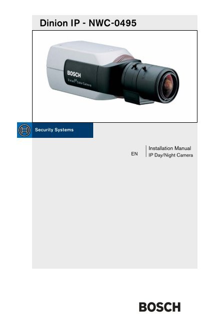
<strong>Dinion</strong> <strong>IP</strong> - <strong>NWC</strong>-<strong>0495</strong>ENInstallation Manual<strong>IP</strong> Day/Night Camera
<strong>Dinion</strong> <strong>IP</strong> | Installation ManualiiCopyrightThis user guide is the intellectual property of <strong>Bosch</strong> Security Systems and is protectedby copyright. All rights reserved. No part of this document may be reproduced ortransmitted for any purpose, by whatever means, electronic or mechanical, without theexpress written permission of <strong>Bosch</strong> Security Systems.Release: May 2006 (Software version 2.0)© Copyright 2006 <strong>Bosch</strong> Security SystemsNoteThis user guide has been compiled with great care and the information it contains hasbeen thoroughly verified. The text was complete and correct at the time of printing.The ongoing development of the products may mean that the content of the user guidecan change without notice. <strong>Bosch</strong> Security Systems accepts no liability for damageresulting directly or indirectly from faults, incompleteness or discrepancies between theuser guide and the product described.TrademarksAll hardware and software product names used in this document are likely to beregistered trademarks and must be treated accordingly.<strong>Bosch</strong> Security Systems | 2006-05
<strong>Dinion</strong> <strong>IP</strong> | Installation ManualEN | iiiContentsImportant Safeguards ............................................................................................viiFCC Information ............................................................................................. viii1. INTRODUCTION .................................................................................11Type number overview .........................................................................................12Unpacking ...............................................................................................................12System requirements ............................................................................................13Overview of functions ...........................................................................................13Wide dynamic range ......................................................................................14Day/Night function .........................................................................................14Power-over-Ethernet ......................................................................................14Receiver ............................................................................................................14Video encoding ...............................................................................................14Tri Streaming ...................................................................................................14Recording .........................................................................................................15Multicast ...........................................................................................................15Configuration ...................................................................................................15Tampering recognition and motion detectors ..........................................15Snapshots ........................................................................................................15Backup ..............................................................................................................152. CONNECTIONS ..................................................................................16Power .......................................................................................................................16Network (and power) ............................................................................................16Video service monitor ...........................................................................................17Alarm connector ....................................................................................................17Lens mounting ........................................................................................................17Mounting the camera ............................................................................................183. QUICK SET-UP ...................................................................................20Back focus adjustment ........................................................................................20Accessing and navigating quick set-up menu ................................................21How to use the navigation keys ..................................................................21<strong>Bosch</strong> Security Systems | 2006-05 | V2.0
<strong>Dinion</strong> <strong>IP</strong> | Installation ManualEN | ivInstall menu .............................................................................................................22Install lens wizard submenu .........................................................................22Install <strong>IP</strong> address submenu ..........................................................................23Defaults .............................................................................................................244. NETWORK CONNECTION ................................................................25System requirements .....................................................................................25Establishing the connection .........................................................................255. OPERATION VIA THE BROWSER .................................................27Livepage ..................................................................................................................27Image selection ...............................................................................................27Digital I/O .........................................................................................................28System log / Event log ..................................................................................28Saving snapshots ...........................................................................................28Recording video sequences ........................................................................28Running recording program .........................................................................29Recordings page ...................................................................................................29Selecting recordings .....................................................................................30Controlling playback ......................................................................................316. CONFIGURATION VIA THE BROWSER .......................................33Settings ...................................................................................................................33General Settings ...................................................................................................35Camera identification .....................................................................................35Password protection ......................................................................................36Language selection ........................................................................................37Date and time ..................................................................................................37Time server .......................................................................................................38Display stamping ............................................................................................38Encoder Settings ..................................................................................................39Selecting an encoder profile ........................................................................40Changing profiles ...........................................................................................41JPEG posting ..................................................................................................44Camera settings ....................................................................................................45Current profile ........................................................................................................45Profiles ..............................................................................................................46ALC ....................................................................................................................46<strong>Bosch</strong> Security Systems | 2006-05 | V2.0
<strong>Dinion</strong> <strong>IP</strong> | Installation ManualEN | vShutter/AGC ...................................................................................................47Day/Night .........................................................................................................48Enhance ............................................................................................................49Color ..................................................................................................................50Back Light Compensation (BLC) ...............................................................51Installer Options ....................................................................................................52Recording ................................................................................................................52Type ...................................................................................................................53Storage information ........................................................................................53iSCSI settings ........................................................................................................54Scan iSCSI <strong>IP</strong> address .................................................................................54iSCSI LUN map ..............................................................................................55Target <strong>IP</strong> address ...........................................................................................55Target name .....................................................................................................55Target LUN .......................................................................................................55Target password .............................................................................................55Initiator name ...................................................................................................56Initiator extension ............................................................................................56Decoupling the drive used ...........................................................................56Storage information ........................................................................................56Partitioning .............................................................................................................57Creating a partition ........................................................................................57Saving changes ..............................................................................................58Editing a partition ............................................................................................59Deleting partitions ..........................................................................................60Recording scheduler ............................................................................................61Activating a partition for recording .............................................................61Continuous recording ....................................................................................62Recording status ............................................................................................62Alarm recording ..............................................................................................63Properties ........................................................................................................64Alarm Settings .......................................................................................................67Alarm in .............................................................................................................67Alarm connections ..........................................................................................67Video content analysis ........................................................................................69Analysis .............................................................................................................69Analysis type ....................................................................................................70Motion detector ...............................................................................................70<strong>Bosch</strong> Security Systems | 2006-05 | V2.0
<strong>Dinion</strong> <strong>IP</strong> | Installation ManualEN | viSensitivity .........................................................................................................70Tamper detection ...........................................................................................71Alarm e-mail ............................................................................................................74Send alarm e-mail ...........................................................................................74Mail server <strong>IP</strong> address ...................................................................................74Layout ................................................................................................................74Attach JPEG from camera ............................................................................75Destination address .......................................................................................75Sender name ...................................................................................................75Send e-mail for testing ..................................................................................75Relay Settings ........................................................................................................75Alarm out ..........................................................................................................75Service Settings ....................................................................................................76Network ............................................................................................................76Multicasting ......................................................................................................78Version information ........................................................................................79Livepage configuration ..................................................................................80Licenses ..................................................................................................................82Firmware and configuration upload ............................................................82Function test ...........................................................................................................847. CONNECTIONS BETWEEN VIDEO SERVERS ............................85Installation ........................................................................................................85Establishing the connection .........................................................................85Connect on alarm ...........................................................................................85Connecting with a Web browser ...............................................................86Closing the connection .................................................................................868. OPERATION WITH DECODER SOFTWARE ................................879. MAINTENANCE ..................................................................................88Testing the network connection .........................................................................88Repairs .....................................................................................................................88Transfer and disposal ....................................................................................88<strong>Bosch</strong> Security Systems | 2006-05 | V2.0
<strong>Dinion</strong> <strong>IP</strong> | Installation ManualEN | vii10. TROUBLESHOOTING ........................................................................8911. SPECIFICATIONS ..............................................................................91Dimensions ......................................................................................................9212. ACCESSORIES ...................................................................................93Recommended lenses ...................................................................................93Power transformers ........................................................................................9313. GLOSSARY ..........................................................................................94<strong>Bosch</strong> Security Systems | 2006-05 | V2.0
<strong>Dinion</strong> <strong>IP</strong> | Installation ManualEN | viiSAFETY PRECAUTIONSDangerThe lightning flash with arrowhead symbol, within an equilateral triangle, isintended to alert the user to the presence of uninsulated “dangerousvoltage” within the product's enclosure that may be of sufficient magnitudeto constitute a risk to persons.WarningThe exclamation mark within an equilateral triangle is intended to alert theuser to the presence of important operating and maintenance (servicing)instructions in the literature accompanying the appliance.Important Safeguards1. Read these instructions.2. Keep these instructions.3. Comply with all warnings.4. Follow all instructions.5. Do not use this equipment near water.6. Clean only with dry cloth.7. Do not block any ventilation openings. Install in accordance with themanufacturer’s instructions.8. Do not install near any heat sources such as radiators, heat registers, stoves,or other equipment (including amplifiers) that produce heat.9. Do not defeat the safety purpose of the polarized or grounding-type plug. Apolarized plug has two blades with one wider than the other. A groundingtype plug has two blades and a third grounding prong. Both the wide bladeand the third prong are provided for your safety. If the supplied plug does notfit into your outlet, consult an electrician for advice.10. Protect the power cord from being walked on or pinched particularly atplugs, convenience receptacles, and the point where they exit from theequipment.11. Only use attachments/accessories specified by the manufacturer.<strong>Bosch</strong> Security Systems | 2006-05 | V2.0
EN | viii<strong>Dinion</strong> <strong>IP</strong> | Installation Manual12. Unplug this equipment during lightning storms or when unused for longperiods of time.13. Refer all servicing to qualified service personnel. Servicing is required whenthe equipment has been damaged in any way, such as when power supplycord or plug is damaged, liquid has been spilled or objects have fallen intothe equipment, the equipment has been exposed to rain or moisture, does notoperate normally, or has been dropped.14. An all-pole mains switch with a contact separation of at least 3mm in eachpole shall be incorporated in the electrical installation of the building.WarningTo reduce the risk of electric shock, do not remove covers. No userserviceableparts inside. Refer servicing to qualified service personnel.WarningTo reduce the risk of fire or electric shock, this apparatus should not beexposed to rain or moisture and objects filled with liquids, such as vases,should not be placed on this apparatus.FCC InformationThis equipment has been tested and found to comply with the limits for a Class Bdigital device, pursuant to part 15 of the FCC Rules. These limits are designed toprovide reasonable protection against harmful interference in a residentialinstallation. This equipment generates, uses and can radiate radio frequencyenergy and, if not installed and used in accordance with the instructions, maycause harmful interference to radio communications. However, there is noguarantee that interference will not occur in a particular installation. If thisequipment does cause harmful interference to radio or television reception,which can be determined by turning the equipment off and on, the user isencouraged to try to correct the interference by one or more of the followingmeasures:• Reorient or relocate the receiving antenna.• Increase the separation between the equipment and receiver.<strong>Bosch</strong> Security Systems | 2006-05 | V2.0
<strong>Dinion</strong> <strong>IP</strong> | Installation ManualEN | ix• Connect the equipment into an outlet on a circuit different from that to whichthe receiver is connected.• Consult the dealer or an experienced radio/ TV technician for help.NoteAny change or modification of the equipment not expressly approved by<strong>Bosch</strong> could void the user's authority to operate the equipment.For additional information or to speak to a representative, please contact the<strong>Bosch</strong> Security Systems location nearest to you or visit our web site atwww.boschsecuritysystems.comOnly for EU countriesDo not dispose of electric tools together with householdwaste material!In observance of European Directive 2002/96/EC on wasteelectrical and electronic equipment and its implementation inaccordance with national law, electric tools that have reachedthe end of their life must be collected separately and returnedto an environmentally compatible recycling facility.CautionThe power supply unit must comply with EN/UL 60950 or equivalentsafety standard. The power supply unit must be a SELV (Safety Extra LowVoltage) source with single fault protection. IEEE802.3af compliant powersources are SELV devices by default.<strong>Bosch</strong> Security Systems | 2006-05 | V2.0
EN | x<strong>Dinion</strong> <strong>IP</strong> | Installation Manual<strong>Bosch</strong> Security Systems | 2006-05 | V2.0
<strong>Dinion</strong> <strong>IP</strong> | Installation ManualEN | 11Introduction 1The <strong>Dinion</strong> <strong>IP</strong> Day/Night is a high-performance smart surveillance color camera.It incorporates 15-bit digital signal processing for outstanding pictureperformance under all lighting conditions. The camera operates as a networkvideo server and transmits video and control signals over data networks such asEthernet LANs and the Internet.The <strong>Dinion</strong> <strong>IP</strong> Day/Night is easy to install and ready to use, and offers the bestsolution for demanding scene conditions. Features include:• Day/Night camera with mechanically switching IR filter• Three pre-programmed operation modes• Noise elimination, true color reproduction• Adaptive dynamic range optimization• Enhanced video motion detection• Video and data transmission over <strong>IP</strong> data networks• Tri Streaming function for simultaneous encoding with three individuallydefinable profiles• Multicast function for simultaneous picture transmission to multiple receivers• One analog composite video output CVBS (PAL/NTSC)• Video encoding using international MPEG-4 standard• Integrated Ethernet interface (10/100 Base-T)• Remote control of all built-in functions via TCP/<strong>IP</strong>• Password protection to prevent unauthorized connection or configurationchanges• Relay input for external sensor (such as door contacts)• Event-driven, automatic connection (for example at switch-on and for alarms)<strong>Bosch</strong> Security Systems | 2006-05 | V2.0
<strong>Dinion</strong> <strong>IP</strong> | Installation ManualEN | 12• Fast, convenient configuration using the integrated Web server and a browser• Firmware update through flash memory• Convenient upload and download of configuration dataType number overviewType number <strong>NWC</strong>-<strong>0495</strong>-10P <strong>NWC</strong>-<strong>0495</strong>-20PStandard 50 Hz 60 HzSupply voltage24 VAC or 12 VDC (use class 2 power supply) orPoE (IEEE 802.3af)CCD type 1/3"UnpackingUnpack carefully and handle the equipment with care. The packaging contains:• <strong>Dinion</strong> XF Day/Night <strong>IP</strong> camera• CS to C lens mount adapter• CCD protection cap• Spare lens connector (male)• CD ROM– Quick Installation Guide– Manual– Configuration Manager– MPEG ActiveX control– MPEG viewer– Adobe Acrobat Reader• Quick install instructionsNoteIf equipment appears to have been damaged during shipment, repack it inthe original packaging and notify the shipping agent or supplier.<strong>Bosch</strong> Security Systems | 2006-05 | V2.0
<strong>Dinion</strong> <strong>IP</strong> | Installation ManualEN | 13System requirements• Computer with Windows 2000/XP operating system, network access andMicrosoft Internet Explorer web browser version 6.0 or lateror• Computer with Windows 2000/XP operating system, network access andreception software, for example VIDOS or DIBOS 8.0or• MPEG-4 compatible hardware decoder from <strong>Bosch</strong> Security Systems (such asV<strong>IP</strong> XD) as a receiver and a connected video monitorThe minimum PC requirements are:• Operating platform: A PC running Windows 2000 or Windows XP with IE6.0• Processor: 1.8 GHz Pentium IV• RAM memory: 256 MB• Video system: 128 MB video memory, 1024x768 display with 24-bit color• Network interface: 100-BaseT• DirectX: 9.0bNoteMake sure the graphics card is set to 16-bit or 32-bit color depth and thatMicrosoft Virtual Machine or Java Virtual Machine is installed on yourPC. To play back live video images, an appropriate MPEG ActiveX mustbe installed on the computer. If necessary, install the required software andcontrols from the product CD provided. If you need further assistance,contact your PC system administrator.Overview of functionsThe camera incorporates a network video server. Its primary function is toencode video and control data for transmission over an <strong>IP</strong> network. With itsMPEG-4 encoding it is ideally suited for <strong>IP</strong> communication and for remoteaccess to digital video recorders and multiplexers. The use of existing networksmeans that integration with CCTV systems or local networks can be achievedquickly and easily. Video images from a single camera can be simultaneouslyreceived on several receivers.<strong>Bosch</strong> Security Systems | 2006-05 | V2.0
EN | 14<strong>Dinion</strong> <strong>IP</strong> | Installation ManualWide dynamic rangeA unique combination of 15-bit digital video processing that enhances sensitivityand XF-Dynamic which extends the dynamic range, provides a sharper, moredetailed image with outstanding accuracy in color reproduction. The 15-bitdigital signal is automatically processed to optimally capture the detail in boththe high and low light areas of the scene simultaneously, maximizing theinformation visible in the picture.Day/Night functionThe Day/Night function provides enhanced night viewing by increasing the IRsensitivity. The camera is equipped with a motorized IR filter which can beremoved in low-light or IR illuminated applications. The IR filter can beswitched from color to monochrome automatically by either sensing theillumination level or via the alarm input.Power-over-EthernetPower for the camera can be supplied via a Power-over-Ethernet (IEEE 802.3af)compliant network cable connection. With this configuration, only a single cableconnection is required to view, power and control the camera.ReceiverMPEG-4 compatible hardware decoders (for example V<strong>IP</strong> XD) can be used as areceiver. Computers with decoding software such as VIDOS or computers withthe Microsoft Internet Explorer web browser installed can also be used asreceivers.Video encodingThe camera uses the MPEG-4 compression standard. Thanks to efficientencoding, the data rate remains low even with high image quality and can also beadapted to local conditions within wide limits.Tri StreamingTri Streaming allows the incoming data stream to be encoded simultaneouslyaccording to three different, individually customized profiles. This creates twoMPEG4 streams per camera that can serve different purposes, for example onefor local recording and one optimized for transmission over the LAN, and anadditional JPEG stream for use with a PDA for example.<strong>Bosch</strong> Security Systems | 2006-05 | V2.0
<strong>Dinion</strong> <strong>IP</strong> | Installation ManualEN | 15RecordingThe <strong>NWC</strong>-<strong>0495</strong> can be used with an iSCSI server connected via the network tostore long-term recordings.MulticastIn suitably configured networks, the multicast function enables simultaneous, realtime transmission to multiple receivers. The prerequisite for this is that the UDPand IGMP V2 protocols are implemented on the network.ConfigurationThe camera can be configured using a browser on the local network (Intranet) orfrom the Internet. Similarly, firmware updates and rapid loading of deviceconfigurations are also possible. Configuration settings can be stored as files on acomputer and copied from one camera to another.Tampering recognition and motion detectorsThe <strong>NWC</strong>-<strong>0495</strong> offers a wide range of configuration options for alarm signalingin the event of tampering with the camera. An algorithm for detecting movementin the video image is also part of the scope of delivery and can optionally beextended to include special video analysis algorithms.SnapshotsIndividual video frames (snapshots) can be called up as JPEG images, stored onthe hard drive or displayed in a separate browser window.BackupThe browser application Livepage has an icon for saving the video imagesprovided by the unit as a file on your computer's hard drive. Clicking this iconstores the video sequences and they can be replayed with the MPEG viewer from<strong>Bosch</strong> Security Systems included with the package.<strong>Bosch</strong> Security Systems | 2006-05 | V2.0
EN | 16<strong>Dinion</strong> <strong>IP</strong> | Installation ManualConnections 2PowerCautionEnsure that your power supply matches the rated voltage of your camerabefore installing.CautionNever supply power via the power connector when power is supplied viathe Ethernet connection (PoE).10mmVIDEOALARMDC 12VAC 24VETH• use a class 2 power supply• 24 VAC or 12 VDC• push in the tabs to open the quick-connectors(these connections are not polarity sensitive).• use AWG16 to 22 stranded wire or AWG16 to26 solid wire; cut back 10mm (0.4") ofinsulation.Network (and power)CautionNever supply power via the Ethernet connection (PoE) when power issupplied via the power connector.UTP Cat 5 RJ45VIDEOALARMDC 12VAC 24VETH• connect the camera to a 10/100 Base-Tnetwork.• use a shielded UTP Category 5 cable withRJ45 connectors.• Power can be supplied to the camera via theEthernet cable compliant with the Power-over-Ethernet (IEEE 802.3af) standard.<strong>Bosch</strong> Security Systems | 2006-05 | V2.0
<strong>Dinion</strong> <strong>IP</strong> | Installation ManualEN | 17NoteThe multicolored LED under the Ethernet connection indicates Power(red), <strong>IP</strong> connection (green) and <strong>IP</strong> traffic (green flashing). It can bedisabled in the Settings/Camera Settings/Installer optionsmenu.Video service monitorVIDEOALARMDC 12VAC 24V• connect a service monitor to the compositevideo BNC connector to aid installation.• a monitor connected close to the camera viathis connection can also be used in parallel withremote PC viewing.ETHAlarm connectorPin Alarm socket1 Ground2 Alarm in3 Relay out contact 14 Relay out contact 2AlarmPin 4Pin 1• Max. wire diameter AWG 22-28for both stranded and solid.• Default relay position n.o. (normallyopen), no alarm.• Alarm output relay switchingcapability: Max voltage 30VAC or+40VDC. Max 0.5 A continuous,10VA.• Alarm in: TTL logic, +5V nominal,+40VDC max, DC coupled with22kOhm pull-up to +3.3V.• Alarm in: configurable as activelow or active high.• Max. 42V allowed between cameraground and each of the relay pins.Lens mountingThe camera accepts CS-mount lenses with a lens protrusion of up to 5mm.C-mount lenses can be mounted using the lens adapter ring. DC-iris lenses arerecommended for the best picture performance. The camera automaticallydetects the type of lens used and optimizes performance accordingly. A sparemale lens connector is provided.<strong>Bosch</strong> Security Systems | 2006-05 | V2.0
EN | 18<strong>Dinion</strong> <strong>IP</strong> | Installation ManualCautionTo avoid damaging the CCD sensor when using a C-mount lens, makesure the supplied lens adapter ring is mounted onto the camera beforemounting the lens.Lenses weighing more than 0.5 kg (1.1lbs) must be separately supported.<strong>Bosch</strong><strong>Bosch</strong>Pin Video iris lens DC iris lens1 Supply (11.5V ±0.5, 50mA max.) Damp -2 Not used Damp +3 Video signal 1Vpp 1kOhm Drive +4 Ground Drive -NoteIf a short circuit is detected on the lens connector, the on-screen display(OSD) failure message LENS SHORT CIRCUIT is shown. The lens circuitis automatically disabled to avoid internal damage. Remove the lensconnector and check the pin connections.Mounting the cameraThe camera can be mounted from the top or bottom. The bottom mounting isisolated from ground. With outdoor scenes, a DC-iris lens is recommended.<strong>Bosch</strong> Security Systems | 2006-05 | V2.0
<strong>Dinion</strong> <strong>IP</strong> | Installation ManualEN | 19CautionDo not point the camera/lens into direct sunlight.Do not obstruct the free flow of air around the camera.NoteThe camera becomes quite warm when operating; this is normal.However, you should take this into account when touching the camera.<strong>Bosch</strong> Security Systems | 2006-05 | V2.0
EN | 20<strong>Dinion</strong> <strong>IP</strong> | Installation ManualQuick set-up 3The <strong>Dinion</strong> <strong>IP</strong> Day/Night camera normally provides an optimal picture withoutthe need for further adjustments. Configuration of the camera is carried outremotely via the network using a web browser. However, the camera also has anInstaller menu in which basic installation settings (lens wizard, <strong>IP</strong> address) can beaccessed. To view this menu connect a monitor to the composite video output ofthe camera.Back focus adjustmentTo optimize picture sharpness in both bright and low-level lighting, adjust theback focus. Use the camera's unique Lens Wizard. This ensures that the object ofinterest always remains in focus even when focusing at the maximum lensopening.– When back focusing vari-focus lenses, adjust to obtain a sharp picture in bothwide-angle and tele positions for both far and near focus.– When back focusing zoom lenses, ensure the object of interest remains infocus throughout the entire zoom range of the lens.To adjust back focus:1. Open the slide door at the side of the camera2. Unlock the back focus locking button.<strong>Bosch</strong><strong>Bosch</strong>3. Turn the back focus adjustment as required.<strong>Bosch</strong> Security Systems | 2006-05 | V2.0
<strong>Dinion</strong> <strong>IP</strong> | Installation ManualEN | 21<strong>Bosch</strong>4. Lock the back focus locking button.Accessing and navigating quick set-up menuFive keys, located behind the side panel, are used for navigating through thequick set-up menu. To access the set-up menus, press the menu/select key(center). The main menu appears on the monitor.<strong>Bosch</strong><strong>Bosch</strong>How to use the navigation keysUp keyMenu/selectLeft keyRight keyLockDown key• Press the menu/select key to access the menus or to move to the next orprevious menu.• Press the menu/select key for approximately 1.5 seconds to open the Installermenu.• Use the up or down keys to scroll up or down through a menu.<strong>Bosch</strong> Security Systems | 2006-05 | V2.0
EN | 22<strong>Dinion</strong> <strong>IP</strong> | Installation Manual• Use the left or right keys to move through options or to set parameters.• When in a menu, quickly pressing the menu/select key twice restores theselected item to its factory default.• To close all menus at once from any menu, select the Exit item and hold downthe menu/select key until the menu display disappears.Install menuFunction Selection DescriptionLens Wizard Select submenu Select to optimize camera lens combinationNetwork Select submenu Select to set the network <strong>IP</strong> address for the camera(default address is 192.168.0.1)ExitExit the menuInstall lens wizard submenuFunction Selection DescriptionLens Type AUTO, MANUAL,DCIRIS, VIDEOIn AUTO mode the camera auto detects the type oflens used or force the camera into a mode.DetectedIf the LENS TYPE detection is in AUTO, thedetected lens type is shown.Set BackFocus NowSet LVLExitAdjustment procedure DC-iris LensSelect to force lens to its maximum opening. Afterfocusing the lens the object of interest remains infocus in bright and low light conditions.(Video iris lenses only). The level detector indicatormust be set to the center by adjusting the levelpotentiometer on the lens, to obtain the best pictureperformance.Return to the INSTALL menu1. Unlock the back focus locking button.2. Access the Lens Wizard menu.3. Set Back Focus Now is highlighted in the menu.4. Turn the back focus adjustment as required.5. Lock the back focus locking button.6. Exit the menu.<strong>Bosch</strong> Security Systems | 2006-05 | V2.0
<strong>Dinion</strong> <strong>IP</strong> | Installation ManualEN | 23Adjustment procedure Manual-iris Lens1. Unlock the back focus locking button.2. Adjust the lens to the maximum lens opening.3. Turn the back focus adjustment as required.4. Lock the back focus locking button.Adjustment procedure Video-iris Lens1. Unlock the back focus locking button.2. Access the Lens Wizard menu.3. Set Back Focus Now is highlighted in the menu.4. Turn the back focus adjustment as required.5. Lock the back focus locking button.6. Select Set LVL in the menu; the Level bar appears.7. Point the camera at the scene it will be mostly viewing.8. Adjust the level potentiometer located on the lens until the Level bar is inthe central position.9. Exit the menu.NoteThe best performance with video iris lenses is obtained when the peak/average potentiometer of the lens matches the peak/average balanceconfiguration setting.Install <strong>IP</strong> address submenuTo operate the camera in your network, a network-valid <strong>IP</strong> address must beassigned. The factory default <strong>IP</strong> address is 192.168.0.1Function Selection Description<strong>IP</strong> AddressEnter an <strong>IP</strong> address for the camera. Use LEFT/RIGHT to change position in the address, use UP/DOWN to select the digit. Use SELECT to exit theaddress edit screen.Subnet Mask Enter the Subnet mask (default 255.255.255.0)GatewayEnter a Gateway address.ExitReturn to the Install menu<strong>Bosch</strong> Security Systems | 2006-05 | V2.0
EN | 24<strong>Dinion</strong> <strong>IP</strong> | Installation ManualNoteThe new <strong>IP</strong> address, subnet mask and gateway address are set after youleave the menu. The camera reboots internally and the new values are setafter a few seconds.DefaultsTo restore all parameters (including <strong>IP</strong> address) to the factory defaults, press andhold the Up navigation key for at least 10 seconds and then confirm. Allow a fewseconds for the camera to optimize the picture after a mode reset.NoteRestoring the factory defaults may result in the loss of the <strong>IP</strong> connection.If this occurs, change the <strong>IP</strong> address of your browser to the factory defaultvalue. Only restore the factory defaults when it is absolutely necessary.<strong>Bosch</strong> Security Systems | 2006-05 | V2.0
<strong>Dinion</strong> <strong>IP</strong> | Installation ManualEN | 25Network connection 4A computer with Microsoft Internet Explorer can be used to receive live imagesfrom the camera, control cameras and replay sequences stored on the local harddrive. The camera is configured over the network using the browser or via theConfiguration Manager (supplied with the product). The configuration optionsusing the menu system of the camera itself are limited to setting up the lens andnetwork.NoteThe camera can also be connected to DIBOS 8.0, VIDOS and BVMSvideo management systems as well as third party video managementsystems.System requirements• Microsoft Internet Explorer (version 6.0 or higher)• Monitor resolution 1024 × 768 pixels• Network access (Intranet or Internet)To play back live video images, an appropriate MPEG ActiveX must be installedon the computer. If necessary, the required software and controls can be installedfrom the product CD provided.– Insert the CD into the CD-ROM drive of the computer. If the CD does notstart automatically, open the root directory of the CD in Windows Explorerand double click MPEGAx.exe.– Follow the on-screen instructions.Establishing the connectionThe camera must be assigned a valid <strong>IP</strong> address to operate on your network. Thedefault address pre-set at the factory is 192.168.0.1– Start the Web browser.– Enter the <strong>IP</strong> address of the camera as the URL.<strong>Bosch</strong> Security Systems | 2006-05 | V2.0
EN | 26<strong>Dinion</strong> <strong>IP</strong> | Installation ManualPassword protection in cameraIf the camera is password-protected, a message to enter the password appears.NoteA camera offers you the option of limiting access across variousauthorization levels.– Enter the user name and the associated password in the appropriate fields.– Click OK. If the password is correct, the desired page is displayed.After a short time when the connection is established, the Livepage with thevideo image appears. In the application title bar the Livepage selection is used tooperate the camera; the Settings selection is used to configure the camera andthe application interface.NoteIf the connection is not established, the maximum number of possibleconnections may already have been reached. The maximum number ofconnections depends on the device and network configuration.<strong>Bosch</strong> Security Systems | 2006-05 | V2.0
<strong>Dinion</strong> <strong>IP</strong> | Installation ManualEN | 27Operation via the browser 5LivepageAfter the connection is established, the Livepage is initially displayed. It showsthe live video image on the right of the browser window. Depending on theconfiguration, various text overlays may be visible on the live video image. Otherinformation may also be shown next to the live video image on the Livepage.The display depends on the settings on the Livepage configuration page.Image selectionYou can view the image on a full screen.– Click on one of the MPEG-4 Stream 1, MPEG-4 Stream 2 or M-JPEG tabsbelow the video image to switch between the different displays for the cameraimage.<strong>Bosch</strong> Security Systems | 2006-05 | V2.0
EN | 28<strong>Dinion</strong> <strong>IP</strong> | Installation ManualDigital I/ODepending on the configuration of the unit, the alarm input and the relay outputare displayed next to the camera image. The alarm symbol is for information andindicates the input status of the alarm input: Active 1 = Symbol is green, Active 0= Symbol not lit. The relay on the camera allows you to operate a device (forexample a light or a door opener).– To operate, click the relay symbol next to the video image. The symbol is redwhen the relay is activated.System log / Event logThe System log field contains information about the operating status of thecamera and the connection. These messages can be saved automatically in a file.Events such as the triggering or end of alarms are shown in the Event log field.These messages can be saved automatically in a file.Saving snapshotsIndividual images from the video sequence that is currently being shown on theLivepage can be saved in JPEG format on the computer's hard drive.– Click the camera icon to save single images.– The image is saved at a resolution of 704 × 576/480 pixels (4CIF). Thestorage location depends on the configuration of the camera.Recording video sequencesSections of the video sequence that is currently being shown on the Livepage canbe saved on the computer's hard drive. The sequences are recorded at the<strong>Bosch</strong> Security Systems | 2006-05 | V2.0
<strong>Dinion</strong> <strong>IP</strong> | Installation ManualEN | 29resolution specified in the encoder configuration. The storage location dependson the configuration of the camera.– Click the recording icon to record video sequences.– Saving begins immediately. The red dot on the icon flashes to indicate that arecording is in progress.– Click the symbol for recording video sequences again. Saving is terminated.Installing MPEG viewerYou can play back saved video sequences using the MPEG viewer from<strong>Bosch</strong> Security Systems, which can be found on the software CD supplied.NoteA corresponding MPEG ActiveX (located on the CD provided with theproduct) must be installed on the computer in order to play back savedvideo sequences using the MPEG viewer.– Insert the CD into the CD-ROM drive of the computer. If the CD does notstart automatically, open the CD in the Windows Explorer.– Open the MPEG Viewer directory and copy the file MPEGViewer.exe toyour computer's hard drive.– If necessary, you can also start the MPEG viewer by double-clicking the fileMPEGViewer.exe.Running recording programThe hard drive icon below the camera image on the Livepage changes during anautomatic recording to the RAM memory of a <strong>NWC</strong>-<strong>0495</strong> or to an iSCSI storagedevice.The icon lights up and displays a moving graphic to indicate a runningrecording. If no recording is taking place, a gray icon is displayed.Recordings pageYou can access the Recordings page for playing back recorded video sequencesfrom the Livepage as well as from the Settings menu.<strong>Bosch</strong> Security Systems | 2006-05 | V2.0
EN | 30<strong>Dinion</strong> <strong>IP</strong> | Installation ManualThe Recordings link is only visible if a storage medium has been selected (seepage 50).• Click in the navigation bar in the upper section of the window on the linkRecordings. The playback page appears.Selecting recordingsIn the left section of the page, first select the partition whose recordings you wantto view.All sequences that are saved in the partition are displayed in the list. A runningnumber (track) is assigned to each sequence. Start time and stop time, recordingduration, number of alarms, and recording type are displayed.• Click a partition name from the list to display the recordings for this partition.• Click a list entry. The playback for the selected sequence starts immediately inthe video window.<strong>Bosch</strong> Security Systems | 2006-05 | V2.0
<strong>Dinion</strong> <strong>IP</strong> | Installation ManualEN | 31Controlling playbackYou will see a time bar below the video image for quick orientation. If aparticular sequence has been selected for playback by means of click, the selectedsequence is highlighted. The associated time interval is displayed in the bar inblue. A green arrow above the bar indicates the position of the image currentlybeing played back within the sequence.The time bar offers various options for navigation in and between sequences.• You can change the time interval displayed by moving the blue area to the leftor right while holding down the mouse button.• You can change the time interval displayed by clicking the plus or minusicons. The display can span a range from two months to a few seconds.• You can select a different sequence for playback by clicking on thecorresponding blue marking.• If required, drag the green arrow to the point in time at which the playbackshould begin. Alternatively you can double-click directly in the blue timeinterval or in the timescale to jump to the position selected in this manner.The date and time display below the bar provides orientation to the second.You can control playback by means of the buttons below the video image.The buttons have the following functions:Start playbackPause playbackJump to start of active video sequence orto previous sequence in the list<strong>Bosch</strong> Security Systems | 2006-05 | V2.0
EN | 32<strong>Dinion</strong> <strong>IP</strong> | Installation ManualJump to end of active video sequence orto next sequence in the listYou can use the slide control to control playback speed and fast forward/rewind:positioning in the middle indicates playback at recording speed, left indicatesrewind, and right fast forward. The fast forward or rewind speed changes,depending on how far you move the slide control toward the icons.You can continuously select playback speed by means of the speed regulator:Red bars within the blue sequence fields indicate the points in time where alarmswere triggered. Drag the green arrow to navigate to these points quickly.In addition, you can set markers in the sequences, so-called bookmarks, andjump directly to these. These bookmarks are indicated as small yellow arrowsabove the time interval. Use the bookmarks as follows:Jump to the previous bookmarkSet bookmarkJump to the following bookmark• Right-click a bookmark to delete it.NoteBookmarks are only valid while you are in the Recordings page; they arenot saved with the sequences. As soon as you leave the page all bookmarksare deleted.<strong>Bosch</strong> Security Systems | 2006-05 | V2.0
<strong>Dinion</strong> <strong>IP</strong> | Installation ManualEN | 33Configuration via the browser 6SettingsWhen a connection is established, the Livepage is initially displayed. ClickSettings in the application title bar to configure the camera and the applicationinterface. A new page containing the configuration menu is opened.All settings are stored in the camera memory, and they are preserved even if thepower is interrupted.Configuration menu treeThe configuration menu tree allows all parameters of the camera to beconfigured. The configuration menu is recommended for expert users or systemadministrators. All unit parameters can be accessed in this mode. Changes that<strong>Bosch</strong> Security Systems | 2006-05 | V2.0
EN | 34<strong>Dinion</strong> <strong>IP</strong> | Installation Manualinfluence the fundamental functioning of the unit (for example firmware updates)can only be made using the configuration menu.You can view the current settings by opening one of the configuration pages.– Click on one of the menu options on the left of the window. The associatedsub-menu is opened.– Click one of the links in the sub-menu. The corresponding page is opened.The settings are changed by entering new values or by selecting a pre-definedvalue in a list field.<strong>Bosch</strong> Security Systems | 2006-05 | V2.0
<strong>Dinion</strong> <strong>IP</strong> | Installation ManualEN | 35Saving changesAfter making changes in a window, click the Set button to send the new settingsto the unit and save them there.NoteSave the changes made in each window by clicking Set. Clicking the Setbutton saves only the settings in the current window. Changes in any otherfields are ignored.Click on the Settings link at the top of the window to close the window withoutsaving the changes made.General SettingsVarious basic data for the camera can be set or selected here.Camera identificationCamera nameThe camera can be assigned a name to assist in identifying it. The namesimplifies the management of multiple devices in more extensive systems, forexample using the VIDOS software.NoteThe camera name is used for remote identification of a unit, in the eventof an alarm for example. Enter a name that makes it as easy as possible toidentify the location unambiguously.Camera IDEach camera should be assigned a unique identifier that can be entered here asan additional means of identification.<strong>Bosch</strong> Security Systems | 2006-05 | V2.0
EN | 36<strong>Dinion</strong> <strong>IP</strong> | Installation ManualPassword protectionA camera is generally protected by a password to prevent unauthorized access tothe unit. You can use various authorization levels (User name:) to limit access.NoteProper password protection is only guaranteed if all higher authorizationlevels are also protected with a password. For example, if a live passwordis assigned, a service and a user password should also be set. Whenassigning passwords, you should always start from the highestauthorization level.User nameThe camera recognizes three user names: service, user and live, whichcorrespond to different authorization levels.• The user name service represents the highest authorization level. Afterentering the corresponding password, you can use it to access all the functionsof the camera and change all configuration settings.• The user name user represents the middle authorization level. You can use itto operate the unit and also to control cameras, but you cannot change theconfiguration.• The user name live represents the lowest authorization level. It can only beused to view the live video image and switch between the different live imagedisplays.PasswordYou can define and change a separate password for each user name if you arelogged on as Service or if the unit is not protected by a password. Enter thepassword for the selected user name here.Confirm passwordRe-enter the new password to rule out typing mistakes.<strong>Bosch</strong> Security Systems | 2006-05 | V2.0
<strong>Dinion</strong> <strong>IP</strong> | Installation ManualEN | 37NoteThe new password is then saved by clicking the Set button. You shouldtherefore click the Set button immediately after entering and confirmingthe password, even if you also want to assign a password to another username.Language selectionWebsite languageSelect the language for the user interface here.Date and timeDate formatChoose the desired date format here(Europe: DD.MM.YYYY; USA: MM.DD.YYYY; Japan: YYYY/MM/DD).Unit date and timeIf there are a number of devices operating in your system or network, it isimportant to synchronize their internal clocks. For example, it is only possible tocarry out correct identification and evaluation of recordings occurring at thesame time if all devices are operating on the same time.– Enter the current date. Since the unit time is controlled by the internal clock,it is not necessary to enter the day of the week. This is added automatically.– Enter the current time or click Synchr. PC to apply the system time from yourcomputer to the camera.<strong>Bosch</strong> Security Systems | 2006-05 | V2.0
EN | 38<strong>Dinion</strong> <strong>IP</strong> | Installation ManualTime serverThe camera can receive the time signal from a time server using the time serverprotocol (RFC 868) and then use it to set the internal clock. The device calls upthe time signal automatically every ten minutes.Time zoneSelect the time zone in which the system is located.Time settingsSelect this during daylight savings time if the time change is to be taken intoaccount. Deactivate the check box to switch to winter time.Time server <strong>IP</strong> addressEnter the <strong>IP</strong> address of a time server working with the RFC 868 protocol.Display stampingVarious overlays or stamps in the video image provide important supplementaryinformation. These overlays can be enabled individually and arranged on theimage in a clear manner.Camera name stampingThis field sets the position of the camera name overlay. It can be displayed at theTop, at the Bottom or at a position of your choice using the Custom option. Or itcan be set to Off if no overlay of this information is to be shown.<strong>Bosch</strong> Security Systems | 2006-05 | V2.0
<strong>Dinion</strong> <strong>IP</strong> | Installation ManualEN | 39Time stampingThis field sets the position of the time and date overlay. It can be displayed at theTop, at the Bottom or at a position of your choice, which you have pre-definedusing HyperTerminal, using the Custom option. Or it can be set to Off if nooverlay of this information is to be shown.Alarm mode stampingChoose On if a text message should be overlaid in the event of an alarm. It canbe displayed at a position of your choice using the Custom option. Or it can beset to Off if no overlay of this information is to be shown.– Select the desired position from the lists.– If you have selected the Custom option, additional fields are displayed tospecify the exact position (Position (XY):).– In the Position (XY): fields enter the values for the desired position.Displayed alarm messageEnter the message to be displayed for an alarm. It can contain up to31 characters.Video watermarkingChoose On if the video images transmitted are to be watermarked. Afteractivation, all images are marked with a small green rectangle. A red rectangleindicates that the sequence (live or saved) has been manipulated.Encoder SettingsFor encoding the video signal, you can select two profiles and change the presetsfor the profiles.<strong>Bosch</strong> Security Systems | 2006-05 | V2.0
EN | 40<strong>Dinion</strong> <strong>IP</strong> | Installation ManualSelecting an encoder profileYou can adapt the MPEG-4 data transmission to the operating environment (forexample network structure, bandwidth, data structures). To do this, the camerasimultaneously generates two data streams (Dual Streaming), for which you canselect different compression settings, for example one setting for transmissions tothe Internet and one for LAN connections.Pre-programmed profiles are available, which each give priority to differentperspectives.• Profile 1: Low bandwidth (CIF)High quality for low bandwidth connections, resolution 352 × 288/240 pixels• Profile 2: Low delay (2/3 D1)High quality with low delay, resolution 464 × 576/480 pixels• Profile 3: High resolution (4CIF/D1)High resolution for high bandwidth connections, resolution 704 × 576/480pixels• Profile 4: DSLFor DSL connections at 500 kBit/s, resolution 352 × 288/240 pixels• Profile 5: ISDN (2B)For ISDN connections via two B channels, resolution 352 × 288/240 pixels• Profile 6: ISDN (1B)For ISDN connections via one B channel, resolution 352 × 288/240 pixels• Profile 7: ModemFor analog modem connections at 20 kBit/s, resolution 352 × 288/240 pixels• Profile 8: GSMFor GSM connections at 9,600 baud, resolution 176 × 144/120 pixels<strong>Bosch</strong> Security Systems | 2006-05 | V2.0
<strong>Dinion</strong> <strong>IP</strong> | Installation ManualEN | 43I-frame video qualityThis setting allows you to adjust the image quality of the I-frames. The Autooption automatically adjusts the quality to the settings for the P-frame videoquality. Selecting Manual allows you to set a value between 4 and 31 on a slidebar. The value 4 represents the best quality with, if necessary, a lower framerefresh rate depending on the settings for the maximum data rate. A value of 31results in a very high refresh rate and lower image quality.I-frame distanceThis parameter determines the number of inter-coded frames between twoI-frames.Encoding intervalThe figure selected here determines the interval at which images are encodedand transmitted. For example, entering 4 means that only every fourth image isencoded, the following three images are skipped – this can be particularlyadvantageous with low bandwidths.Video resolutionHere, you can select the desired resolution for the MPEG-4 video image. Thefollowing resolutions are available:• QCIF 176 × 144/120 pixels• CIF 352 × 288/240 pixels• 1/2 D1 352 × 576/480 pixels• 2CIF 704 × 288/240 pixels• 4CIF/D1 704 × 576/480 pixels• 2/3 D1 464 × 576/480 pixelsProfile resetClick Default to return the profile to the factory default values.<strong>Bosch</strong> Security Systems | 2006-05 | V2.0
EN | 44<strong>Dinion</strong> <strong>IP</strong> | Installation ManualJPEG postingYou can save individual JPEG images on an FTP server at certain intervals. Youcan then retrieve these images at a later date to reconstruct alarm events ifrequired.JPEG formatSelect the resolution you wish the JPEG images to have:• Small 176 × 144 pixels (QCIF)• Medium 352 × 288 pixels (CIF)• Large 704 × 576 pixels (4CIF)File nameYou can select how file names will be created for the individual images which aretransmitted.• Overwrite: The same file name is always used and any existing file will beoverwritten with the current file.• Increment: A number from 000 to 255 is added to the file name andautomatically incremented by 1. When it reaches 255 it starts again from 000.• Date/time suffix: The date and time are automatically added to the filename. When setting this parameter, please ensure that the date and time ofthe unit are always correctly set. Example: the file snap021606_124530.jpgwas stored on February 16, 2006 at 12.45 p.m. and 30 seconds.JPEG posting intervalEnter the interval in seconds at which the images will be sent to an FTP server.Enter zero if you do not want any images to be sent.<strong>Bosch</strong> Security Systems | 2006-05 | V2.0
<strong>Dinion</strong> <strong>IP</strong> | Installation ManualEN | 45FTP server <strong>IP</strong> addressEnter the <strong>IP</strong> address of the FTP server on which you wish to save the JPEGimages.FTP server loginEnter your login name for the FTP server.FTP server passwordEnter the password that gives you access to the FTP server.Path on FTP serverEnter the exact path on which you wish to post the images on the FTP server.Post JPEG from cameraCheck the box to activate one or more camera inputs for the JPEG image. Anenabled camera input is indicated by a check mark.NoteThe numbering follows the labeling of the video inputs on the actual unit.Camera settingsCurrent profileNoteIf the camera is in monochrome mode, all color related menu items aredisabled and cannot be accessed.<strong>Bosch</strong> Security Systems | 2006-05 | V2.0
EN | 46<strong>Dinion</strong> <strong>IP</strong> | Installation ManualProfilesThe camera has three pre-programmed operating profiles that can be selected inthe Profile menu. These profiles are pre-programmed by default but you canadjust them according to your preferences. The Profile menu allows you to selectand set-up the picture enhancement functions for each profile. If you are nothappy with your changes, you can always recall the default values for the profile.Select operating profile 1, 2, or 3.Profile IDEnter a name for the selected profile.Profile defaultsSelect to restore the factory defaults. A confirmation screen appears. Allow 5seconds for the camera to optimize the picture after a profile reset.ALC<strong>Bosch</strong> Security Systems | 2006-05 | V2.0
<strong>Dinion</strong> <strong>IP</strong> | Installation ManualEN | 47Video levelAdjust the video output level (-15 to 0 to +15).Peak AverageAdjust the balance between peak and average video control (-15 to 0 to +15).At -15 the camera controls the average video level, at +15 the camera controls thepeak video level.ALC SpeedAdjust the speed of the video level control loop (Slow, Medium or Fast).Shutter/AGCShutter– AES (auto-shutter) - the camera automatically sets the optimum shutter speedfor manual iris lenses. The camera tries to maintain the selected shutter speed(1/60 [1/50], 1/100, 1/120, 1/250, 1/500, 1/1000, 1/2000, 1/5000, 1/10K) aslong as the light level of the scene permits.– FL - flickerless mode avoids interference from light sources (recommendedfor use with video iris or DC iris lenses only).– FIXED - allows a user defined shutter speed (1/60 [1/50], 1/100, 1/120, 1/250, 1/500, 1/1000, 1/2000, 1/5000, 1/10K).Sensitivity UpSelects the factor by which the sensitivity of the camera is increased (OFF, 2x, 3x,…, 10x).<strong>Bosch</strong> Security Systems | 2006-05 | V2.0
EN | 48<strong>Dinion</strong> <strong>IP</strong> | Installation ManualNoteIf Sensitivity Up is active, some noise or spots may appear in the picture.This is normal camera behavior. Sensitivity Up may cause some motionblur on moving objects.GainIn AGC mode the camera automatically sets the gain to the lowest possible valueneeded to maintain a good picture. Select the maximum value the gain can haveduring AGC operation (0, 1, ... 26).In FIXED mode the gain is set at a predefined not scene dependent value. Selectthe gain setting (0, 1, ... 26).Day/NightThe <strong>Dinion</strong> <strong>IP</strong> Day/Night camera is equipped with a motorized IR filter. The IRfilter can be removed in low-light or IR illuminated applications. There are fourdifferent methods of switching:• via the alarm input,• as part of the programmable mode profile,• automatically, based on the observed light levels, or• via the settings page.If Auto switching mode is selected, the camera automatically switches the filterdepending on the observed light level. The switching level is programmable. Setthe video level at which the camera switches to monochrome operation (-15 to 0to +15). In monochrome mode the IR filter is removed, giving full IR sensitivity.<strong>Bosch</strong> Security Systems | 2006-05 | V2.0
<strong>Dinion</strong> <strong>IP</strong> | Installation ManualEN | 49In Auto switching mode set the camera priority:– Motion: the camera gives sharp images without motion blur as long as thelight level permits.– Color: the camera gives color pictures as long as the light level permits.The camera recognizes IR illuminated scenes to prevent unwanted switching tocolor mode.There are two modes for IR contrast:– Enhanced: the camera optimizes contrast in applications with high IRillumination levels.– Normal: the camera optimizes contrast in mono applications with visible lightillumination.EnhanceAuto BlackAutoblack ON automatically increases the visibility of details.Black LevelAdjusts the black level between 0 and approximately 110mV. Zero position ofslider corresponds to the factory default black level.ContourAdjusts the sharpness of the picture. 0 corresponds to the default position.<strong>Bosch</strong> Security Systems | 2006-05 | V2.0
EN | 50<strong>Dinion</strong> <strong>IP</strong> | Installation ManualDynamic Noise ReductionIn AUTO mode the camera automatically reduces the noise in the picture. Thismay cause some motion blur on moving objects.Enhanced Dynamic RangeIn XF-DYN mode the camera automatically optimizes the contrast in the picture.ColorWhite Balance– ATW: Auto tracking white balance allows the camera to constantly adjust foroptimal color reproduction.– AWB HOLD: Puts the ATW on hold and saves the color settings.– In MANUAL mode the Red, Green and Blue gain can be manually set to adesired position.WB SpeedAdjust the speed of the white balance control loop.Red GainATW mode and AWB hold mode: adjusts the Red gain to optimize the whitepoint.Green GainATW mode and AWB hold mode: adjusts the Green gain to optimize the whitepoint.<strong>Bosch</strong> Security Systems | 2006-05 | V2.0
<strong>Dinion</strong> <strong>IP</strong> | Installation ManualEN | 51Blue GainATW mode and AWB hold mode: adjusts the B gain to optimize around thewhite point.SaturationAdjusts the color saturation. -15 will lead to a monochrome imageBack Light Compensation (BLC)When ON, the video level is optimized for the selected area of the image. Partsoutside this area may be underexposed or overexposed (this is normal). To set-upan area for BLC, click Area Selection.Selecting an area<strong>Bosch</strong> Security Systems | 2006-05 | V2.0
EN | 52<strong>Dinion</strong> <strong>IP</strong> | Installation ManualWhen you click Area Selection a pop-up window appears with a still picture ofthe received video. Use your mouse to select an area in the picture. BLC Leveladjusts the balance between the selected BLC area and its surrounding.Installer OptionsSelect the synchronization method for the camera: Internal for free runningcamera operation; Line Lock to lock to the power supply frequency.You can disable the buttons on the camera to prevent unauthorized change of thecamera settings. You can also disable the LED at the rear of the camera to avoidit interfering with the image sensing of the camera.Click the Restore all defaults button to restore the factory defaults. Aconfirmation screen appears. Allow 5 seconds for the camera to optimize thepicture after a mode reset.RecordingYou can record the images from the camera in the RAM memory of the unit orin an appropriately configured iSCSI storage device.Local RAM memory is suitable for short-term recordings and pre-alarmrecordings in Ring mode operation.<strong>Bosch</strong> Security Systems | 2006-05 | V2.0
<strong>Dinion</strong> <strong>IP</strong> | Installation ManualEN | 53For long-term, authoritative images, it is essential that you use appropriately sizediSCSI storage.TypeSelect the desired storage medium to subsequently configure the recordingparameters.If you select RAM storage as the storage medium, the recording is started withthe preconfigured parameters immediately after you click the Set button. You canmodify the settings by stopping the recording on the Recording scheduler andthen performing the required modifications (see page 61).The preconfigured setting for RAM recordings is: continuous ring recording with8 MB storage size and 1 image per second in CIF format.CautionIf you switch the storage medium from iSCSI server to RAM recording,the settings on the page iSCSI settings will be lost and can only be restoredby reconfiguring them.Storage informationThe status of the currently selected storage medium and the data throughput aredisplayed here for information. You cannot change any of these settings.• Click Advanced to view a status report with logged actions. A new windowwill open.• In this window, click Delete to delete all entries. The entries will be deletedimmediately; you cannot undo this process.• Click the Close button to close the window.<strong>Bosch</strong> Security Systems | 2006-05 | V2.0
EN | 54<strong>Dinion</strong> <strong>IP</strong> | Installation ManualiSCSI settingsIf you select type iSCSI server as the storage medium, you then need to set up aconnection to the desired iSCSI storage device and set the configurationparameters.NoteThe storage device selected must adhere to the iSCSI specification, beavailable on the network and be completely set up. Amongst other things,it must have an <strong>IP</strong> address and be divided into logical drives (LUN).Scan iSCSI <strong>IP</strong> address• Enter the <strong>IP</strong> address of the required iSCSI server here.• Click the Scan button. The connection to the <strong>IP</strong> address will be established.The iSCSI LUN map field contains the corresponding logical drives.<strong>Bosch</strong> Security Systems | 2006-05 | V2.0
<strong>Dinion</strong> <strong>IP</strong> | Installation ManualEN | 55iSCSI LUN mapThe LUN map displays the logical drives configured for the iSCSI storage device.The current user is displayed for each drive.• Double-click a free drive (LUN). The associated information is called up andautomatically displayed in the fields below the map.• If the logical drive is password protected, you must first enter the password inthe Target password field and click the Set button.NoteIn cases where the information cannot be read due to the networktopology, you must enter the data manually, so that the <strong>NWC</strong>-<strong>0495</strong> canaccess the drive. In this case you should ensure that the entries correspondexactly with the configuration of the iSCSI device.• After entering all the settings in the relevant fields, click Set. The <strong>NWC</strong>-<strong>0495</strong>attempts to create a connection to the required drive using this data.As soon as a connection has been established, the selected drive is used forrecordings.Target <strong>IP</strong> addressEnter the <strong>IP</strong> address of the required iSCSI server here.Target nameEnter the name of the required drive.Target LUNEnter the LUN of the required drive.Target passwordIf the drive is password protected, enter the password.NoteYou may not enter a new password. This is only possible by configuringthe iSCSI storage device.<strong>Bosch</strong> Security Systems | 2006-05 | V2.0
EN | 56<strong>Dinion</strong> <strong>IP</strong> | Installation ManualInitiator nameThe initiator name is automatically displayed after a connection has beenestablished.Initiator extensionEnter the initiator extension. For the sake of clarity, you can enter a name or theexisting extension with a comment, for example "– Camera 2"Decoupling the drive usedEach drive can only be associated with one user. If a drive is already being usedby another person, you can decouple the drive and connect the drive with the<strong>NWC</strong>-<strong>0495</strong>.• Double-click a drive that is already being used in the LUN map. You will seea warning message.• Confirm the decoupling of the current user. The drive is released and can beconnected to the <strong>NWC</strong>-<strong>0495</strong>.Storage informationThe status of the currently selected storage medium and the data throughput aredisplayed here for information. You cannot change any of these settings.• Click Advanced to view a status report with logged actions. A new windowwill open.• In this window, click Delete to delete all entries. The entries will be deletedimmediately; you cannot undo this process.• Click the Close button to close the window.<strong>Bosch</strong> Security Systems | 2006-05 | V2.0
<strong>Dinion</strong> <strong>IP</strong> | Installation ManualEN | 57PartitioningA partition can be set up for recordings of the camera in a similar manner to thepartitioning often found on computer hard drives. Parameters such as size,quality and type of video recording or compression standard used can bespecified for the partition. Modifying these parameters leads to reorganization,during which stored data is lost.In addition, the page provides you with an overview of the drive data; forexample total memory. A pie chart indicates how much memory space ispartitioned for recordings.Creating a partitionCautionModifications to the size of partitions lead to the entire hard drive beingreorganized and the loss of all sequences stored on the drive.Consequently, you should check the recordings before any modification tothe parameters mentioned and back up important sequences on thecomputer's hard drive.Creating a new partition is performed using separate windows in whichinformation is presented to you and you are led step by step through thenecessary settings.<strong>Bosch</strong> Security Systems | 2006-05 | V2.0
EN | 58<strong>Dinion</strong> <strong>IP</strong> | Installation Manual• Click the Create partition button to start the assistant for creating partitions.The first window appears.• You should always first read the information text in the upper section of thewindow.• Click in the text fields to enter values or use the other controls that areavailable, such as buttons, checkboxes or list fields.• Click the Next>> button in the lower section of the window to continue withthe next step.• Click the
<strong>Dinion</strong> <strong>IP</strong> | Installation ManualEN | 59CautionAll modifications to settings are only effective if you complete theconfiguration in the last window by clicking Finish.• Switch to the last window if necessary.• Click Finish to complete the configuration. All settings are now transferred tothe unit and subsequently become effective.Editing a partitionYou can modify the configuration of a partition at any time.CautionAll modifications result in the re-organization of the partition and the lossof all sequences on this partition. Changes to the size of a partition (Totalpartition size) lead to the entire hard drive being reorganized and the lossof all recordings stored on the drive. Consequently, you should back up all<strong>Bosch</strong> Security Systems | 2006-05 | V2.0
EN | 60<strong>Dinion</strong> <strong>IP</strong> | Installation Manualimportant sequences on the computer's hard drive before modifying thepartition.You can perform the required modifications in the Partition properties window.• Click the Edit partition button. A new window with the entries for the selectedpartition is opened.• Enter the necessary changes.• Click the Set button to save the modifications.• After closing the window, click the Set button in the main window to transferthe changes to the unit and to save them.Deleting partitionsYou can delete a partition at any time.CautionDeleting a partition leads to the entire hard drive being reorganized andloss of all sequences stored on the drive. Consequently, you should checkthe recordings before deleting any partition and back up importantsequences on the computer's hard drive.• Click the Delete partition button to delete the highlighted partition. The linecontaining the associated number remains in the display, the partition numberis deleted and the size is indicated as 0.• Click the Set button to transfer the changes to the unit and to save them.<strong>Bosch</strong> Security Systems | 2006-05 | V2.0
<strong>Dinion</strong> <strong>IP</strong> | Installation ManualEN | 61Recording schedulerSet all parameters for recording. Recording can be performed continuously or inthe case of an alarm.Activating a partition for recordingAfter configuration, you can activate the partition for recording by clicking theStart button.After starting, the pages Continuous recording, Alarm recording and theProperties for the activated partitions are displayed in gray, and the configurationcannot be modified.The graphic in the lower section of the pages indicates this partition's recordingactivity. You will see an animated graphic while recording is taking place. Youcan terminate recording at any time and deactivate the partition.• Click the Start button to activate the currently selected partition for recording.• Click the Stop button to deactivate the currently selected partition forrecording. Recordings that are currently running will be interrupted and theconfiguration can be modified.<strong>Bosch</strong> Security Systems | 2006-05 | V2.0
EN | 62<strong>Dinion</strong> <strong>IP</strong> | Installation ManualContinuous recordingYou can specify the times during which continuous recording to the hard driveshould take place.Separate selection fields are available for each day of the week. You can select upto 16 individual recording time intervals for each day of the week.NoteIf a time interval has already been selected for alarm recording, you cannotselect it for continuous recording (see Alarm recording, page 63).• Left-click the point in the schedule at which recording should start and holdthe button down.• Drag the selected field to the desired recording end and then release themouse key.• Right-click a highlighted time interval to delete it.• Click the Select all button to highlight all time intervals.• Click the Clear all button to delete all highlighted time intervals.Recording statusThe graphic indicates the recording activity in this partition. You will see ananimated graphic while recording is taking place.<strong>Bosch</strong> Security Systems | 2006-05 | V2.0
<strong>Dinion</strong> <strong>IP</strong> | Installation ManualEN | 63Alarm recordingYou can specify the times during which images from the camera should berecorded in the event of an alarm.You can select up to 16 individual recording time intervals for each day of theweek. Alarm recording occurs only during the highlighted time intervals.NoteIf a time interval has already been selected for continuous recording, youcannot select it for alarm recording (see Continuous recording, page 62).CautionAlarm tracks must be set up in the required partition for alarm recording(see Number of alarm tracks, page 64).The unit uses a special recording mode during alarm recording for optimal usageof storage capacity: as soon as a time gap for alarm recording begins, a recordingis continuously made on one segment, which is the size of a complete alarmsequence (pre- and post-alarm time).This segment in the partition functions in a similar manner to a ring buffer and isoverwritten until an alarm is actually triggered. Recording occurs on the segment<strong>Bosch</strong> Security Systems | 2006-05 | V2.0
EN | 64<strong>Dinion</strong> <strong>IP</strong> | Installation Manualonly for the duration of the preset post-alarm time and a new segmentsubsequently used in the same manner.This ensures that the alarm recorded is always secured for its entire duration andthe space required to save each alarm recording is easy to calculate.PropertiesYou can view the current properties directly in the recording scheduler andmodify them if necessary. You can also activate the alarms that should triggerrecording. Similarly, you can also select the profile for recording.CautionAll modifications result in the re-organization of the partition and the lossof all sequences on this partition. Changes to the size of a partition (Totalpartition size) lead to the entire hard drive being reorganized and the lossof all recordings stored on the drive. Consequently, you should back up allimportant sequences on the computer's hard drive.Partition nameYou can enter a new name for the partition.<strong>Bosch</strong> Security Systems | 2006-05 | V2.0
<strong>Dinion</strong> <strong>IP</strong> | Installation ManualEN | 65Video inputThe number of the video input is displayed for information purposes.• Select the required data stream from the list field.Type of recordingSelect the required recording type.In the case of Ring mode the recording proceeds continuously. If the maximumhard drive space has been reached, the oldest recordings are automaticallyoverwritten.In the case of Linear mode the recording proceeds until the entire hard drivespace is full. The recording is then stopped until old recordings have beendeleted.Recording profileSelect the profile that is to be active during recording. You can view and modifythe parameters for the profile (see MPEG-4 encoder, from page 43).NoteThe recording profile can deviate from the standard setting Active profilefor the video input set and is only used during an active recording.Number of alarm tracksSelect the number of alarm tracks to be used in the partition. One alarm eventcan be recorded in each alarm track. Accordingly, the number of alarms enteredcan be recorded and archived. A partition can contain a maximum of 128 alarmrecordings.If the option Ring mode (see page 65) is set for a partition, the latest alarmrecordings are always saved in the preset number. If the option Linear mode isselected, the recording is stopped as soon as the total number of alarm tracks hasbeen recorded.Already Used alarm tracks are displayed in the graphic next to the parameter.Alarm recordingSelect which time intervals are to be covered for Pre-alarm and Post-alarm.<strong>Bosch</strong> Security Systems | 2006-05 | V2.0
EN | 66<strong>Dinion</strong> <strong>IP</strong> | Installation ManualAlarm recording atYou can select the alarm sensor that is to trigger a recording. You can also use themotion alarm to trigger the alarm recording.NoteThe alarm sensor must be active to be able to trigger the recording.The alarm input is activated on the page Alarm sources (see page 67). Themotion alarm is configured and activated on the page Video contentanalysis (see page 69).• Check the box for the alarm sensor that is to trigger a recording. The alarmsensors selected are indicated by a check mark.Total partition sizeThis displays how much storage space the partition occupies on the drive.Already Used file tracks are displayed in the graphic next to the parameter.Remaining for recordingThis displays the maximum remaining recording time. The value is automaticallyupdated after the parameters have been modified.Free spaceThis displays how much space is still available in the partition.Used spaceThis displays how much space is already used in the partition.Format!You can delete all recordings in a partition at any time.CautionCheck the recordings before deleting and back up important sequences onthe computer's hard drive.• Click the Format! button to delete all recordings in the currently selectedpartition.<strong>Bosch</strong> Security Systems | 2006-05 | V2.0
<strong>Dinion</strong> <strong>IP</strong> | Installation ManualEN | 67Alarm SettingsHere, you can make the settings for the alarm sources and alarm connections.Alarm inYou can configure the possible alarm triggers for the camera.Alarm input 1Select the option On in order to activate the alarm via the correspondingexternal alarm sensor. Otherwise, select Off.Select Active Low if the alarm is to be triggered by closing the contact. SelectActive High if the alarm is to be triggered by opening the contact.NameYou can enter a name for each alarm input, which is then displayed below theicon for the alarm input on the Livepage during configuration.Alarm connectionsYou can select the response of the camera in case of an alarm. In case of an alarm,the camera can automatically establish a connection to a predefined <strong>IP</strong> address(compatible MPEG-4 compatible hardware receiver or computer with receptionsoftware). You can enter up to ten <strong>IP</strong> addresses which will be selected in order bythe unit in case of an alarm until a connection is established.<strong>Bosch</strong> Security Systems | 2006-05 | V2.0
EN | 68<strong>Dinion</strong> <strong>IP</strong> | Installation ManualConnect on alarmSelect On so that the camera automatically establishes a connection to a predefined<strong>IP</strong> address in the event of an alarm.NoteStream 2 is always transmitted for alarm connections. This should be takeninto account when assigning the profile.Number of destination <strong>IP</strong> addressHere you assign the numbering for the <strong>IP</strong> addresses to be contacted in the eventof an alarm. The unit contacts the remote locations one after the other in thenumbered sequence until a connection has been established.Destination <strong>IP</strong> addressFor each number, enter the corresponding <strong>IP</strong> address for the desired remotelocation.Destination passwordIf the remote location is password protected, enter the password here.Auto-connectSelect On if an active connection should be re-established automatically to one ofthe previously specified <strong>IP</strong> addresses after each restart, connection breakdown ornetwork failure.NoteStream 2 is always transmitted for automatic connections. This should betaken into account when assigning the profile.<strong>Bosch</strong> Security Systems | 2006-05 | V2.0
<strong>Dinion</strong> <strong>IP</strong> | Installation ManualEN | 69Video content analysisThe <strong>NWC</strong>-<strong>0495</strong> contains an integrated Video Content Analysis (VCA), whichcan detect and analyze changes in the signal. Such changes can be due tomovements in the camera's field of view.You can configure the video content analysis for the camera.If necessary, click the Default button to return all settings to their default values.AnalysisSelect the option On to activate the video content analysis.As soon as the video content analysis is activated, metadata are created.Depending on the Analysis type selected and the relevant configuration,additional information overlays the video image in the small window. If you haveselected MOTION+ analysis, for example, the sensor fields will light up in whichmovement is registered.<strong>Bosch</strong> Security Systems | 2006-05 | V2.0
EN | 70<strong>Dinion</strong> <strong>IP</strong> | Installation ManualNoteOn the Livepage configuration page, you can enable additionalinformation overlays for the live video image too (see page 88).Analysis typeSelect the required analysis algorithm. By default, only MOTION+ is available –this offers a motion detector and essential recognition of tampering. The currentalarm status is displayed for information purposes.NoteAdditional analysis algorithms with comprehensive functions such asIVMD are available from <strong>Bosch</strong> Security Systems.Motion detectorFor the detector to function, the following conditions must be met:• Analysis must be activated.• At least one sensor field must be activated.• The individual parameters must be configured to suit the operatingenvironment and the desired responses.• The sensitivity must be set to a value greater than zero.CautionReflections of light (off glass surfaces, etc.), switching lights on or off orchanges in the light level caused by cloud movement on a sunny day cantrigger unintended responses from the motion detector and generate falsealarms. Run a series of tests at different times of the day and night to ensurethat the video sensor is operating as intended.For indoor surveillance, ensure constant lighting of the areas during theday and at night.SensitivityThe basic sensitivity of the motion detector can be adjusted for theenvironmental conditions to which the camera is subject.The sensor reacts to variations in the brightness of the video image. The darkerthe observation area, the higher the value that must be selected.<strong>Bosch</strong> Security Systems | 2006-05 | V2.0
<strong>Dinion</strong> <strong>IP</strong> | Installation ManualEN | 71Min. object sizeYou can specify the number of sensor fields that a moving object must cover togenerate an alarm. This setting prevents objects that are too small from triggeringan alarm.A minimum value of 4 is recommended. This value corresponds to four sensorfields.Selecting the areaThe areas of the image to be monitored by the motion detector can be selected.The video image is subdivided into 858 square sensor fields. You can activate ordeactivate each of these fields individually. If you wish to exclude particularregions of the camera's field of view from monitoring due to continuousmovement (by a tree in the wind, etc.), the relevant fields can be deactivated.• Click Select area to configure the sensor fields. A new window will open.• If necessary, click Clear all first to clear the current selection (fields markedred).• Left-click the fields to be activated. Activated fields are marked red.• If necessary, click Select all to select the entire video frame for monitoring.• Right-click any fields you wish to deactivate.• Click OK to save the configuration.• Click the close button (X) in the window title bar to close the window withoutsaving the changes.Tamper detectionYou can reveal the tampering of cameras and video cables by means of variousoptions. Run a series of tests at different times of the day and night to ensure thatthe video sensor is operating as intended.NoteThe options for tamper detection can only be set for fixed cameras. Domecameras or other motorized cameras cannot be protected in this manner asthe movement of the camera itself causes changes in the video image thatare too great.<strong>Bosch</strong> Security Systems | 2006-05 | V2.0
EN | 72<strong>Dinion</strong> <strong>IP</strong> | Installation ManualGlobal change %You can define the percentage of sensor fields that must register a changesimultaneously before generating an alarm. This setting is independent of thesensor fields selected under Select area.This option allows you to detect, independently of motion alarms, manipulationof the orientation or location of a camera resulting from turning the cameramounting bracket, for instance.SensitivityNoteThis and the following parameter are only accessible if the reference checkis activated.The basic sensitivity of the tamper detection can be adjusted for theenvironmental conditions to which the camera is subject.The algorithm reacts to the differences between the reference image and thecurrent video image. The darker the observation area, the higher the value thatmust be selected.Trigger delayYou can set delayed alarm triggering. The alarm is only triggered after a set timeinterval in seconds has elapsed and then only if the triggering condition stillexists. If the original condition has been restored before this time interval elapses,the alarm is not triggered. This allows you to avoid false alarms triggered byshort-term changes, for example cleaning activities in the direct field of vision ofthe camera.Scene too brightActivate this function if tampering associated with exposure to extreme light (forinstance, shining a flashlight directly on the objective) should trigger an alarm.The average brightness of the scene provides a basis for recognition.Scene too darkActivate this function if tampering associated with covering the objective (forinstance, by spraying paint on it) should trigger an alarm. The average brightnessof the scene provides a basis for recognition.<strong>Bosch</strong> Security Systems | 2006-05 | V2.0
<strong>Dinion</strong> <strong>IP</strong> | Installation ManualEN | 73Scene too noisyActivate this function if tampering associated with EMC interference (noisy sceneas the result of a strong interference signal in the vicinity of the video lines), as anexample, should trigger an alarm.Reference checkYou can save a reference image that is continuously compared with the currentvideo image. If the current video image in the marked areas differs from thereference image, an alarm is triggered. This allows you to detect tampering thatwould otherwise not be detected, for example if the camera is turned.• Click Reference to save the currently visible video image as a reference.• Click Select area and select the areas in the reference image that are to bemonitored.• Check the box Reference check to activate the on-going check. The storedreference image is displayed in black and white below the current videoimage, and the selected areas are marked in red.Selecting the areaYou can select the image areas in the reference image that are to be monitored.The video image is subdivided into 858 square fields. You can activate ordeactivate each of these fields individually.NoteSelect only those areas for reference monitoring in which no movementtakes place and that are always evenly lit, as false alarms could otherwisebe triggered.• Click Select area to configure the sensor fields. A new window will open.• If necessary, click Clear all first to clear the current selection (fields markedred).• Left-click the fields to be activated. Activated fields are marked red.• If necessary, click Select all to select the entire video frame for monitoring.• Right-click any fields you wish to deactivate.• Click OK to save the configuration.<strong>Bosch</strong> Security Systems | 2006-05 | V2.0
EN | 74<strong>Dinion</strong> <strong>IP</strong> | Installation Manual• Click the close button (X) in the window title bar to close the window withoutsaving the changes.Alarm e-mailAs an alternative to automatic connecting, alarm states can also be documentedby e-mail. In this way it is possible to notify a recipient who does not have avideo receiver. In this case the <strong>NWC</strong>-<strong>0495</strong> automatically sends an e-mail to apreviously defined e-mail address.Send alarm e-mailSelect On if you want the unit to automatically send an alarm e-mail in the eventof an alarm.Mail server <strong>IP</strong> addressEnter the <strong>IP</strong> address of a mail server that operates on the SMTP standard (SimpleMail Transfer Protocol). Outgoing e-mails are sent to the mail server via theaddress you entered. Otherwise leave the box blank (0.0.0.0).LayoutYou can select the data format of the alarm message.• Standard (with JPEG): e-mail with JPEG image file attachment.• SMS: e-mail in SMS format to an e-mail-to-SMS gateway (for example to sendan alarm by cellphone) without an image attachment.<strong>Bosch</strong> Security Systems | 2006-05 | V2.0
<strong>Dinion</strong> <strong>IP</strong> | Installation ManualEN | 75CautionWhen a cellphone is used as the receiver, make sure to activate the e-mailor SMS function, depending on the format, so that these messages can bereceived. You can obtain information on operating your cellphone fromyour cellphone provider.Attach JPEG from cameraClick the checkbox to select the cameras from which JPEG images are sent.An enabled video input is indicated by a check mark.Destination addressEnter the e-mail address for alarm e-mails here. The maximum address length is49 characters.Sender nameEnter a unique name for the e-mail sender, for example the location of the unit.This will make it easier to identify the origin of the e-mail.Send e-mail for testingTest the e-mail function by clicking the Send now button. An alarm e-mail isimmediately created and sent.Relay SettingsHere, you can make the settings for the alarm sources and alarm connections.Alarm outYou can choose various events that activate the output automatically. Thus, forexample, it is possible to switch on a spotlight in response to a motion alarm andswitch it off again when the alarm is over.<strong>Bosch</strong> Security Systems | 2006-05 | V2.0
EN | 76<strong>Dinion</strong> <strong>IP</strong> | Installation ManualRelay nameThe relay can be assigned a name here. The name is shown on the button next toTrigger relay. The Livepage can also be configured to display the name next tothe relay icon.Trigger relayClick the button to switch the relay manually (for example for testing purposes orto operate a door opener).Service SettingsNetworkThe settings on this page are used to integrate the unit into an existing network.NoteChanges to the <strong>IP</strong> address, subnet mask or gateway address are transferredto the unit by clicking Set.– Click Set after entering a new <strong>IP</strong> address.– To do this, enter the old <strong>IP</strong> address followed by /reset (for instance192.168.0.80/reset) in the address bar of your web browser. When thecamera is restarted it can only be accessed at the new <strong>IP</strong> address.<strong>Bosch</strong> Security Systems | 2006-05 | V2.0
<strong>Dinion</strong> <strong>IP</strong> | Installation ManualEN | 77<strong>IP</strong> addressEnter the desired <strong>IP</strong> address for the camera in this field. The <strong>IP</strong> address must bevalid for the network.Subnet maskEnter the appropriate subnet mask for the set <strong>IP</strong> address here.Gateway addressIf you want the unit to establish a connection to a remote location in a differentsubnet, enter the <strong>IP</strong> address of the gateway here. Otherwise, this field can remainempty (0.0.0.0).HTTP browser portSelect a different HTTP browser port from the list if required. The default HTTPport is 80.Video transmissionIf the unit is used behind a firewall, TCP (Port 80) should be selected as thetransmission protocol. For use in a local network, choose UDP.NoteMulticast operation is only possible with the UDP protocol. The TCPprotocol does not support multicast connections. The MTU value in UDPmode is 1514 bytes.Ethernet link typeIf the camera is connected to the network via a switch, both devices must havethe same preset network connection type. If necessary, ask your networkadministrator what value the associated switch is set to.Choose Auto for an autosensing network connection. If necessary you can set thevalue to 10 or 100 MBit/s for either full or half-duplex mode (FD or HD).NoteMalfunctions can occur (for example image faults) if the network capacityis not sufficient for transmission of the maximum data rate generated bythe camera.<strong>Bosch</strong> Security Systems | 2006-05 | V2.0
EN | 78<strong>Dinion</strong> <strong>IP</strong> | Installation Manual1. SNMP host address / 2. SNMP host addressThe <strong>NWC</strong>-<strong>0495</strong> supports the SNMP (Simple Network Management Protocol) formanaging and monitoring network components, and can send SNMP messagesto <strong>IP</strong> addresses. It supports SNMP MIB II and its traps in their full functionalityin the unified code. If you wish to send SNMP traps, enter the <strong>IP</strong> addresses ofone or two required target devices here.MulticastingIn addition to a 1:1 connection between an encoder and a single receiver(unicast), the camera can enable multiple receivers to receive the video signalfrom an encoder simultaneously. This is either done by duplicating the datastream in the unit and then distributing it to multiple receivers (multi-unicast) orby distributing an individual data stream in the network itself to multiplereceivers in a defined group (multicast). You can enter a dedicated multicastaddress and port for each stream. You can switch between the streams by clickingthe associated tabs.NoteThe prerequisite for multicast operation is a multicast-capable network thatuses the UDP and IGMP protocols. Other group membership protocolsare not supported. The TCP protocol does not support multicastconnections.A special <strong>IP</strong> address (class D address) must be configured for multicast operationin a multicast-enabled network. The network must support group <strong>IP</strong> addressesand the Internet Group Management Protocol (IGMP V2). The address range isfrom 225.0.0.0 to 239.255.255.255. The multicast address can be the same formultiple streams. However, it is then necessary to use a different port in each caseso that multiple data streams are not sent simultaneously using the same port andmulticast address.<strong>Bosch</strong> Security Systems | 2006-05 | V2.0
<strong>Dinion</strong> <strong>IP</strong> | Installation ManualEN | 79Multicast address video 1Enter a valid multicast address for each stream to be operated in multicast mode(duplication of the data streams in the network). With the setting 0.0.0.0 theencoder for the relevant stream operates in multi-unicast mode (copying of datastreams in unit). The camera supports multi-unicast connections for up to fivesimultaneously connected receivers.PortNoteDuplication of data places a heavy demand on the CPU and can lead toimpairment of the image quality under certain circumstances.If there are simultaneous data streams at the same multicast address, you mustassign different ports to each data stream. Enter the port address for the relevantstream here.StreamingClick in the check box to activate multicast streaming mode for the relevantstream. An activated stream is marked with a check.Multicast packet TTLA value can be entered to specify how long the multicast data packets are activeon the network. If multicast is to be run via a router the value must be greaterthan 1.Version informationThe hardware and firmware version numbers are for information only andcannot be altered. Keep a record of these numbers in case technical assistance isrequired.Hardware versionThe hardware version number of the camera is displayed.<strong>Bosch</strong> Security Systems | 2006-05 | V2.0
EN | 80<strong>Dinion</strong> <strong>IP</strong> | Installation ManualFirmware versionThe firmware version number of the camera is displayed.Livepage configurationIn this window, you can adapt the appearance of the Livepage to meet yourrequirements. Options are provided here to display various information andoperating elements in addition to the video image. Moreover, individualbackground graphics can be used for the main window and the upper area of thewindow (banners).NoteEither GIF or JPEG images can be used. The file paths must correspond tothe access mode (for example C:\Images\Logo.gif for access to localfiles or http://www.myhostname.com/images/logo.gif foraccess via the Internet/Intranet).For access via the Internet/Intranet, there must be a connection in order todisplay the image. The image files are not stored on the camera.– Mark the check boxes for the information to be displayed on the Livepage.The selected elements are checked.– Check on the Livepage whether and how the desired items are displayed.Logo URLEnter the path to a suitable background graphic in this field. The image can bestored on a local computer, a local network or at an Internet address.– Click Search if necessary to find a suitable image on the local network.<strong>Bosch</strong> Security Systems | 2006-05 | V2.0
<strong>Dinion</strong> <strong>IP</strong> | Installation ManualEN | 81Device logo URLEnter the path for a suitable image for the upper part of the window (banner)here. The image can be stored on a local computer, a local network or at anInternet address.– Click Search if necessary to find a suitable image on the local network.NoteTo restore the original graphics, simply delete the entries in the Logo URLand Device logo URL fields.Show alarm inputAlarm inputs are displayed next to the video image as icons along with theirassigned names. If an alarm is active the corresponding icon changes color.Show event logThe event messages are displayed with the date and time in a field next to thevideo image.Show system logThe system messages are displayed with the date and time in a field next to thevideo image and provide information about the establishment and termination ofconnections etc.Save event logSelect this option to save event messages in a text file on the local computer. Thisfile can be viewed, edited and printed with any text editor or the standard Officesoftware.Save system logSelect this option to save system messages in a text file on the local computer.This file can be viewed, edited and printed with any text editor or the standardOffice software.File for event logEnter the path for saving the event log here.– If necessary, click Search to find a suitable folder.<strong>Bosch</strong> Security Systems | 2006-05 | V2.0
EN | 82<strong>Dinion</strong> <strong>IP</strong> | Installation ManualFile for system logEnter the path for saving the system log here.– If necessary, click Search to find a suitable folder.Path for JPEG and MPEG filesEnter the path for the storage location of individual images and video sequencesthat you can save from the Livepage.– If necessary, click Search to find a suitable folder.LicensesYou can enter the activation key to release additional functions or softwaremodules.NoteThe activation key cannot be deactivated again and is not transferable toother units.Firmware and configuration uploadFirmware updateThe camera functions and parameters can be updated with firmware. To do this,the current firmware package is transferred to the unit via the network. Thefirmware is installed there automatically. Thus a camera can be serviced andupdated remotely without requiring a technician to make changes to the unit on<strong>Bosch</strong> Security Systems | 2006-05 | V2.0
<strong>Dinion</strong> <strong>IP</strong> | Installation ManualEN | 83site. The latest firmware can be obtained from your customer service center orfrom the <strong>Bosch</strong> Security Systems download area.CautionBefore starting the firmware update, make sure that you have selected thecorrect upload file! Uploading the wrong files can result in the unit nolonger being addressable, requiring it to be replaced.CautionDo not interrupt the firmware installation for any reason! Interruption maylead to faulty coding of the Flash EPROM. This can result in the unit nolonger being addressable, requiring it to be replaced.NoteA firmware update resets all camera parameters to their factory defaultvalues. If you wish to retain the old values first save the configuration byperforming a configuration download. After the firmware update you canreload your parameter values by performing a configuration upload.To update the firmware:– First, save the update file to the hard disk.– Enter the full path for the update file in the field or click Browse... to locateand select the file.– Click Upload to begin transmission to the unit. The progress bar allows you tomonitor the transfer.NoteInstalling new firmware and reconfiguring the camera takes severalminutes.The new firmware is unpacked and the Flash EPROM is reprogrammed. Thetime remaining is shown by the message going to reset Reconnecting in ...seconds. After the upload is completed successfully, the unit will restartautomatically.If the operating status LED lights up red, the upload has failed and must berepeated. To perform the upload, you must switch to a special page:<strong>Bosch</strong> Security Systems | 2006-05 | V2.0
EN | 84<strong>Dinion</strong> <strong>IP</strong> | Installation Manual– In the address bar of your browser, after the unit <strong>IP</strong> address enter/main.htm (for example 192.168.0.80/main.htm).– Repeat the upload.Configuration downloadYou can save configuration data for the camera to a computer and load savedconfiguration data from a computer to the unit.– Click Download; a dialog box appears.– Follow the instructions to save the current settings.Configuration upload– Enter the full path of the file to upload or click Browse... to select the desiredfile.– Make certain that the file to be loaded comes from the same device type asthe unit you want to reconfigure.– Click Upload to begin transmission to the unit. The progress bar allows you tomonitor the transfer.Once the upload is complete, the new configuration is activated. The timeremaining is shown by the message going to reset Reconnecting in ... seconds.After the upload is completed successfully, the unit will restart automatically.Function testThe camera offers a variety of configuration options. Therefore you should checkthat it works properly after installation and configuration. This is the only way toensure that the camera will function as intended in the event of an alarm.Your check should include the following functions:• Can the camera be called remotely?• Does the camera transmit all the data required?• Does the camera respond as desired to alarm events?• Is it possible to control peripheral devices if necessary?<strong>Bosch</strong> Security Systems | 2006-05 | V2.0
<strong>Dinion</strong> <strong>IP</strong> | Installation ManualEN | 85Connections between video servers 7A camera can be used as a transmitter and a compatible MPEG-4 hardwaredecoder with a connected monitor as a receiver using an Ethernet networkconnection. This way it is possible to cover large distances with little effort forinstallation or cabling.InstallationCameras are designed to connect with other V<strong>IP</strong> devices automatically with thecorresponding configuration. This only requires that they be part of a closednetwork. Proceed as follows to install the devices:– Connect the devices to the closed network using Ethernet cables.– Connect them to the mains supply.NoteMake sure the devices are configured for the network environment and thecorrect <strong>IP</strong> address for the remote location to be contacted in the event ofan alarm is set on the Alarm connections configuration page.Establishing the connectionThere are three options for establishing a connection between a transmitter and acompatible receiver in a closed network:• an alarm,• a Web browserConnect on alarmWith the appropriate configuration, a connection between a transmitter and areceiver is established automatically when an alarm is triggered. After a shorttime, the live video image from the transmitter is shown on the connectedmonitor.<strong>Bosch</strong> Security Systems | 2006-05 | V2.0
EN | 86<strong>Dinion</strong> <strong>IP</strong> | Installation ManualThis connection option can also be used to connect a transmitter and acompatible receiver using a switch connected to the alarm input. In this case, nocomputer is needed to establish the connection.Connecting with a Web browserVarious requirements must be met in order to operate using a Web program.NoteTransmitter and receiver must be located in the same subnet to establish ahardware connection with a Web browser.– Use the Web browser to connect to the receiver. Its home page is displayed.– Under Video sources on the page Connections, select the camera. A JPEGsnapshot of the video source selected is displayed on the page.– Click MPEG-4 connection to begin displaying the video images on theconnected monitor.Closing the connectionThe connection may be closed using a Web browser.– Use the Web browser to connect to the receiver. Its home page is displayed.In the title bar of the Monitor window on the page Connections, click on the Xicon to end the display of the video images on the connected monitor.<strong>Bosch</strong> Security Systems | 2006-05 | V2.0
<strong>Dinion</strong> <strong>IP</strong> | Installation ManualEN | 87Operation with decoder software 8The camera video server and VIDOS software combine to provide a highperformancesystem solution.VIDOS is software for operating, controlling and administering CCTVinstallations (such as surveillance systems) at remote locations. It runs underMicrosoft Windows operating systems. Its main job is decoding video, audio andcontrol data from a remote transmitter.There are many options available for operation and configuration operationwhen using a camera with VIDOS. Refer to the software documentation formore details.The camera is also designed to operate with the DIBOS 8.0 digital recorderplatform.<strong>Bosch</strong> Security Systems | 2006-05 | V2.0
EN | 88<strong>Dinion</strong> <strong>IP</strong> | Installation ManualMaintenance 9Testing the network connectionThe ping command can be used to check the connection between two <strong>IP</strong>addresses. This allows you to test whether a device is active in the network.– Open the DOS command prompt.– Type ping followed by the <strong>IP</strong> address of the device.If the device is found, the response appears as " Reply from ... ", followedby the number of bytes sent and the transmission time in milliseconds.Otherwise, the device cannot be accessed via the network. This might bebecause:• The device is not properly connected to the network. Check the cableconnections in this case.• The device is not correctly integrated into the network. Check the <strong>IP</strong> address,subnet mask and gateway address.RepairsCautionNever open the casing of the camera. The unit does not contain any userserviceable parts.Ensure that all maintenance or repair work is performed only by qualifiedpersonnel (electrical engineering or network technology specialists). In case ofdoubt, contact your dealer's technical service center.Transfer and disposalThe camera should only be passed on together with this installation guide. Theunit contains environmentally hazardous materials that must be disposed ofaccording to law. Defective or superfluous devices and parts should be disposedof professionally or taken to your local collection point for hazardous materials.<strong>Bosch</strong> Security Systems | 2006-05 | V2.0
<strong>Dinion</strong> <strong>IP</strong> | Installation ManualEN | 89Troubleshooting 10If you cannot resolve a fault, please contact your supplier or system integrator orgo direct to <strong>Bosch</strong> Security Systems Customer Service.The version numbers of the internal processors can be viewed on a special page.Please note this information before contacting Customer Service.– In the address bar of your browser, after the unit <strong>IP</strong> address enter/version.htm (for example 192.168.0.80/version.htm).– Write down the information or print out the page.The following table is intended to help you identify the causes of malfunctionsand correct them where possible.Malfunction Possible causes SolutionNo imagetransmission toremote location.No connectionestablished, no imagetransmission.The unit does notreport an alarm.Defective camera.Faulty cable connections.The unit's configuration.Faulty installation.Wrong <strong>IP</strong> address.Faulty data transmissionwithin the LAN.The maximum number ofconnections has beenreached.Alarm source is not selected.No alarm response specified.Connect a local monitor to thecamera and check the camerafunction.Check all cables, plugs, contactsand connections.Check all configuration parameters.Check all cables, plugs, contactsand connections.Check the <strong>IP</strong> addresses (terminalprogram).Check the data transmission withping.Wait until there is a free connectionand call the transmitter again.Select possible alarm sources onthe Alarm sources configurationpage.Specify the desired alarm responseon the Alarm connectionsconfiguration page, if necessarychange the <strong>IP</strong> address.<strong>Bosch</strong> Security Systems | 2006-05 | V2.0
EN | 90<strong>Dinion</strong> <strong>IP</strong> | Installation ManualMalfunction Possible causes SolutionThe unit is notoperational afterfirmware upload.Power failure duringprogramming by the updatefile.Have the unit checked by CustomerService and replace if necessary.Incorrect update file. Enter the <strong>IP</strong> address followed by /main.htm in your web browserand repeat the upload.<strong>Bosch</strong> Security Systems | 2006-05 | V2.0
<strong>Dinion</strong> <strong>IP</strong> | Installation ManualEN | 91Specifications 11Type number <strong>NWC</strong>-<strong>0495</strong>-10P <strong>NWC</strong>-<strong>0495</strong>-20PStandard PAL NTSCActive pixels 752x582 768x492Rated supply voltage 24 VAC or 12 VDC or Power-over-Ethernet (IEEE 802.3af)12-28 VAC (50/60 Hz)11-36 VDCMin illumination < 0.4 lux< 0.15 lux (in monochrome mode)ImagerInterline CCDResolution540 TVL (BNC)SNR> 50 dBVideo output1 Vpp, 75 OhmSynchronization Internal or Line Lock selectableShutterAES (1/60 (1/50) to 1/100000), Flickerless, Fixed selectableDay/NightColor, Mono, AutoSens UpAdjustable from OFF to 10xAuto blackOn, Off selectable (maximum level selectable up to 28dB)AGCAGC on or off (0 dB) selectableXF-DYNAutomatic dynamic range enhancement level selectableDNRAutomatic noise filtering ON/OFF selectableContourSharpness enhancement level selectableBLCBLC On or Off selectable, with programmable areaWhite balance Automatic 2500 - 9000K (with AWB hold mode and manualmode)Color saturation Adjustable from monochrome (0%) to 133% colorLens MountCS compatible, C-mount compatible with supplied adapter ringALC lensVideo or DC iris auto detectPower consumption < 8 WDimensions 59 x 67 x 122 mm (2.28 x 2.6 x 4.8 inch) without lens (HxWxL)Weight450g (0.99 lbs) without lensTripod Mount Bottom (isolated) and Top ¼" 20 UNCOperating0° to 40° C (32° to 104° F)temperatureControlsOSD with softkey operation<strong>Bosch</strong> Security Systems | 2006-05 | V2.0
EN | 92<strong>Dinion</strong> <strong>IP</strong> | Installation ManualLAN interfaceVideo encodingprotocolsVideo data rateImage resolutions(PAL/NTSC)Total delayImage refresh rateField/image-basedcodingNetwork protocols1 × Ethernet 10/100 Base-T, automatic adaptation, half/full duplex,RJ-45MPEG-4, JPEG9,600 KBit/s ... 10 MBit/s704 × 576/480 pixels (D1/4CIF)704 × 288/240 pixels (2CIF)704 × 288/240 pixels (1/2 D1)352 × 288/240 pixels (CIF)176 × 144/120 pixels (QCIF)120 ms (PAL/NTSC, MPEG-4, no network delay)1 ... 50/60 fields/s adjustable (PAL/NTSC)TCP, UDP, <strong>IP</strong>, HTTP, IGMP V2, ICMP, ARPDimensions85 (3.346")118 (4.646")34 (1.339")1/4"-20 UNC1/4"-20 UNC48 (1.889")123 (4.843")67 (2.638")59(2.323")Dimensions in mm (inches).<strong>Bosch</strong> Security Systems | 2006-05 | V2.0
<strong>Dinion</strong> <strong>IP</strong> | Installation ManualEN | 93Accessories 12Recommended lenses• LTC 3764/20 Varifocal Lens– 1/2-inch, 4 -12 mm, DC-iris, C-mount, F/1.2-360, 4 pin• LTC 3774/30 Varifocal Lens– 1/2-inch, 10 - 40 mm, DC-iris, C-mount, F/1.4-360, 4-pin• LTC 3783/50 Zoom Lens– 1/2-inch, 8.5 - 85 mm, video-iris, C-mount F/1.6-360, 4-pin• LTC 3793/50 Zoom Lens– 1/2-inch, 8 - 144 mm, video-iris, C-mount, F/1.6-360, 4-pin• LTC 3664/40 Varifocal Lens– 1/3-inch, 2.8 - 11 mm, DC-iris, CS-mount F/1.4-360, 4-pin• LTC 3664/30 Varifocal Lens– 1/3-inch, 3.0 - 8 mm, DC-iris, CS-mount F/1.0-360, 4-pinPower transformers• TC 120PS Power Supply Unit– 110-120 VAC/15 VDC, 50/60 Hz, 300mA• TC 220PS Power Supply Unit– 230 VAC/15 VDC, 50 Hz, 10 VA<strong>Bosch</strong> Security Systems | 2006-05 | V2.0
EN | 94<strong>Dinion</strong> <strong>IP</strong> | Installation ManualGlossary 13Brief explanations of some of the terms and abbreviations found in this userguide are given below.10/100 Base-T IEEE 802.3 specification for 10 or 100 MBit/s EthernetARPAddress Resolution Protocol: a protocol for mapping MACand <strong>IP</strong> addressesBaudUnit of measure for the speed of data transmissionBit/sBits per second, the actual data rateCIFCommon Intermediate Format,video format with 352 x 288/240 pixelsDNSDomain Name ServiceFTPFile Transfer ProtocolFull duplexSimultaneous data transmission in both directions (sendingand receiving)GatewayAccess point to another LAN (subnet)GOPGroup of picturesHTTPHypertext Transfer ProtocolICMPInternet Control Message ProtocolIDIdentification: a machine-readable character sequenceIEEEInstitute of Electrical and Electronics EngineersIGMPInternet Group Management ProtocolInternet ProtocolThe main protocol used on the Internet, normally inconjunction with the Transfer Control Protocol (TCP):TCP/<strong>IP</strong><strong>IP</strong>See Internet Protocol<strong>IP</strong> addressA 4-byte number uniquely defining each device on theInternet. It is usually written in dotted decimal notation with fullstops separating the bytes, for example "209.130.2.193".ISDNIntegrated Services Digital NetworkJPEGAn encoding process for still images (Joint PhotographicExperts Group)kBit/sKilobits per second, the actual data rate<strong>Bosch</strong> Security Systems | 2006-05 | V2.0
<strong>Dinion</strong> <strong>IP</strong> | Installation ManualEN | 95LANLocal area networkMACMPEG-4Net maskParametersQCIFRFC 868RS232/RS422/RS485RTPSubnet maskTCPTelnetTTLUDPURLUTPWANWide area networkSee Local area networkA communications network serving users within a limitedgeographical area, such as a building or a university campus.It is controlled by a network operating system and uses atransfer protocol.Media Access ControlFurther development of MPEG-2, designed for transmissionof audiovisual data at very low transfer rates (for example viathe Internet).A mask that explains which part of an <strong>IP</strong> address is thenetwork address and which part comprises the host address.It is usually written in dotted decimal notation with full stopsseparating the bytes, for example "255.255.255.192".Values used for configurationQuarter CIF, a video format with 176 × 144/120 pixelsA protocol for synchronizing computer clocks over the InternetStandards for serial data transmissionRealtime Transport Protocol; A transmission protocol for realtimevideo and audioSee Net maskTransfer Control ProtocolLogin protocol with which users can log on to a remotecomputer (host) on the InternetTime-To-Live; life cycle of a data packet in station transfersUser Datagram ProtocolUniform Resource LocatorUnshielded Twisted PairSee wide area networkA long distance link used to extend or connect remotelylocated local area networks<strong>Bosch</strong> Security Systems | 2006-05 | V2.0
EN | 96<strong>Dinion</strong> <strong>IP</strong> | Installation Manual<strong>Bosch</strong> Security Systems | 2006-05 | V2.0
<strong>Dinion</strong> <strong>IP</strong> | Installation Manual<strong>Bosch</strong> Security Systems | 2006-05
<strong>Bosch</strong> Sicherheitssysteme GmbHLudwig-Bölkow-Allee85521 OttobrunnGermanywww.bosch-sicherheitssysteme.de<strong>Bosch</strong> Security Systems B.V.P.O. Box 800025600 JB EindhovenThe Netherlandswww.boschsecuritysystems.com9922 141 0xxxxx 06-15© 2006 <strong>Bosch</strong> Security Systems B.V.Subject to change. Printed in Portugal.